Table of Contents
Advertisement
Quick Links
Document information
Info
Content
Keywords
MR-CANHUBK344, S32K344, FS26, SE050, TJA1103, TJA1443,
TJA1463, TJA1153, CANHUBK3
Abstract
Hardware notes describing package contents, instructions, open issues,
fixes, and limitations.
MR-CANHUBK344 Hardware User
Manual
Rev. 0.1 — May 30, 2023
User Manual
COMPANY PUBLIC
Advertisement
Table of Contents

Related Manuals for NXP Semiconductors MR-CANHUBK344


Summary of Contents for NXP Semiconductors MR-CANHUBK344
- Page 1 MR-CANHUBK344 Hardware User Manual User Manual Rev. 0.1 — May 30, 2023 COMPANY PUBLIC Document information Info Content Keywords MR-CANHUBK344, S32K344, FS26, SE050, TJA1103, TJA1443, TJA1463, TJA1153, CANHUBK3 Abstract Hardware notes describing package contents, instructions, open issues, fixes, and limitations.
-
Page 2: Contact Information
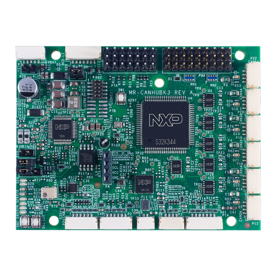
Contact information For more information, please visit: http://www.nxp.com User Manual All information provided in this document is subject to legal disclaimers. © NXP Semiconductors N.V. 2023. All rights reserved. User Manual Rev. 0.1 — May 30, 20223 2 of 31... - Page 3 NXP Semiconductors MR-CANHUBK344 Hardware User Manual 1. Introduction MR-CANHUBK344 board is an evaluation board designed for mobile robotics applications and is based on Arm Cortex -M7 core S32K344 general-purpose automotive ® ® microcontroller featuring the latest in safety, security, and software support.
- Page 4 Mobile Robotics team at the following gitbook URLs: https://nxp.gitbook.io/hovergames/ https://nxp.gitbook.io/mr-canhubk3 User Manual All information provided in this document is subject to legal disclaimers. © NXP Semiconductors N.V. 2023. All rights reserved. User Manual Rev. 0.1 — May 30, 2023 4 of 31 COMPANY PUBLIC...
- Page 5 Real Time Kinematic Global Positioning System (Precision GPS Module) Software Development Kit User Manual All information provided in this document is subject to legal disclaimers. © NXP Semiconductors N.V. 2023. All rights reserved. User Manual Rev. 0.1 — May 30, 2023 5 of 31...
- Page 6 MR-CANHUBK344 Hardware User Manual 2. Contents The MR-CANHUBK344 comes as a kit that includes the items specified on the packing slip documents. Note a reduced kit is also expected to be made available. In the full version the following hardware components are included: •...
- Page 7 Figure 2: JST SY, JST SYP SYR style connectors User Manual All information provided in this document is subject to legal disclaimers. © NXP Semiconductors N.V. 2023. All rights reserved. User Manual Rev. 0.1 — May 30, 2023 7 of 31...
- Page 8 Table 1. Changes Item Description Documentation User Manual All information provided in this document is subject to legal disclaimers. © NXP Semiconductors N.V. 2023. All rights reserved. User Manual Rev. 0.1 — May 30, 2023 8 of 31 COMPANY PUBLIC...
- Page 9 Limitation: xxx. Impact: xxx. User Manual All information provided in this document is subject to legal disclaimers. © NXP Semiconductors N.V. 2023. All rights reserved. User Manual Rev. 0.1 — May 30, 2023 9 of 31 COMPANY PUBLIC...
-
Page 10: Main Components
NXP.com webpages on-line. 5.1.1 S32K344 The S32K344 is an Automotive General Purpose MCU of NXP Semiconductors. Figure 1 gives the block diagram of this chip. The software discussed in this document is running ®... - Page 11 12.0V on P27 or P28 and then inserting the JP1 jumper. Figure 2: JP1 for PMIC Debug mode User Manual All information provided in this document is subject to legal disclaimers. © NXP Semiconductors N.V. 2023. All rights reserved. User Manual Rev. 0.1 — May 30, 2023 11 of 31...
-
Page 12: Board Connections
FS26. 6. Board connections The MR-CANHUBK344 board includes a variety of connectors to permit access to the on- chip interfaces. The intended application space is mobile robotics, which mostly defined the DroneCode JST GH connectors and pinouts. Where an interface did not have a formal DroneCode standard, a typical derivative pinout was used. -
Page 13: Power Input Connectors
0V (GND) Figure 6: P28 Alt Power input connector User Manual All information provided in this document is subject to legal disclaimers. © NXP Semiconductors N.V. 2023. All rights reserved. User Manual Rev. 0.1 — May 30, 2023 13 of 31... -
Page 14: Can Connectors
5.4V output CANx_H 5.0V CANx_L 5.0V User Manual All information provided in this document is subject to legal disclaimers. © NXP Semiconductors N.V. 2023. All rights reserved. User Manual Rev. 0.1 — May 30, 2023 14 of 31 COMPANY PUBLIC... - Page 15 The signal integrity should be validated against your User Manual All information provided in this document is subject to legal disclaimers. © NXP Semiconductors N.V. 2023. All rights reserved. User Manual Rev. 0.1 — May 30, 2023...
- Page 16 Polarity is automatically negotiated Figure 13: P9 100Base-T1 "two wire" connector User Manual All information provided in this document is subject to legal disclaimers. © NXP Semiconductors N.V. 2023. All rights reserved. User Manual Rev. 0.1 — May 30, 2023 16 of 31...
- Page 17 RX (UART13) TX (UART14) RX (UART14) User Manual All information provided in this document is subject to legal disclaimers. © NXP Semiconductors N.V. 2023. All rights reserved. User Manual Rev. 0.1 — May 30, 2023 17 of 31 COMPANY PUBLIC...
- Page 18 Figure 18: I CSE (Secure Element) User Manual All information provided in this document is subject to legal disclaimers. © NXP Semiconductors N.V. 2023. All rights reserved. User Manual Rev. 0.1 — May 30, 2023 18 of 31 COMPANY PUBLIC...
- Page 19 Figure 20: I C0 OLED display Pinout User Manual All information provided in this document is subject to legal disclaimers. © NXP Semiconductors N.V. 2023. All rights reserved. User Manual Rev. 0.1 — May 30, 2023 19 of 31 COMPANY PUBLIC...
-
Page 20: Spi Interfaces
For more general investigation of IMUs please note the NXP Mobile robotics team may have adapter boards (or designs to share) that plug on top of the MR-CANHUBK344 and provide typical IMU components and connector interfaces such as RTK GPS connectors User Manual All information provided in this document is subject to legal disclaimers. - Page 21 Figure 22: Connection of Holybro IMU module Figure 23: IMU pinout and power User Manual All information provided in this document is subject to legal disclaimers. © NXP Semiconductors N.V. 2023. All rights reserved. User Manual Rev. 0.1 — May 30, 2023 21 of 31...
- Page 22 Ensure pin 1 on the PCB silkscreen is aligned with pin 1 on the debugger. Figure 24: JTAG header, P6"DCD-LZ" w/ SWD+Console User Manual All information provided in this document is subject to legal disclaimers. © NXP Semiconductors N.V. 2023. All rights reserved. User Manual Rev. 0.1 — May 30, 2023 22 of 31...
- Page 23 This two-pin connector is suitable for an ISO-14443 NFC antenna system. One is provided in your kit from AMOTECH User Manual All information provided in this document is subject to legal disclaimers. © NXP Semiconductors N.V. 2023. All rights reserved. User Manual Rev. 0.1 — May 30, 2023 23 of 31...
- Page 24 MR-CANHUBK344 Hardware User Manual Figure 26: P10 NFC antenna connector User Manual All information provided in this document is subject to legal disclaimers. © NXP Semiconductors N.V. 2023. All rights reserved. User Manual Rev. 0.1 — May 30, 2023 24 of 31...
- Page 25 Figure 27: Typical RC servo Figure 28: P8A pin header PWM (RC-PWM) User Manual All information provided in this document is subject to legal disclaimers. © NXP Semiconductors N.V. 2023. All rights reserved. User Manual Rev. 0.1 — May 30, 2023 25 of 31...
- Page 26 ADC_POT0. This net then connects to pin 11 – PTE13/ADC1_S19. The potentiometer Figure 30: R84 User Potentiometer User Manual All information provided in this document is subject to legal disclaimers. © NXP Semiconductors N.V. 2023. All rights reserved. User Manual Rev. 0.1 — May 30, 2023 26 of 31...
- Page 27 Figure 31: User Potentiometer Schematic User Manual All information provided in this document is subject to legal disclaimers. © NXP Semiconductors N.V. 2023. All rights reserved. User Manual Rev. 0.1 — May 30, 2023 27 of 31...
-
Page 28: Board Status Leds
NXP Semiconductors MR-CANHUBK344 Hardware User Manual 7. Board status LEDs The MR-CANHUBK344 has various LEDs to indicate status as shown in Figure 6. Under normal circumstances, the state of the LEDs should as indicate in the table below. LED Name... -
Page 29: Legal Information
In no event shall NXP Semiconductors be liable for any indirect, incidental, punitive, special or consequential damages (including - without limitation -... - Page 30 MIFARE4Mobile — is a trademark of NXP B.V. User Manual All information provided in this document is subject to legal disclaimers. © NXP Semiconductors N.V. 2023. All rights reserved. User Manual Rev. 0.1 — May 30, 2023 30 of 31...
- Page 31 NXP Semiconductors MR-CANHUBK344 Hardware User Manual Please be aware that important notices concerning this document and the product(s) described herein, have been included in the section 'Legal information'. © NXP Semiconductors N.V. 2023. All rights reserved. For more information, please visit: http://www.nxp.com...
Need help?
Do you have a question about the MR-CANHUBK344 and is the answer not in the manual?
Questions and answers