
Related Manuals for NXP Semiconductors MPC5775B


Summary of Contents for NXP Semiconductors MPC5775B
- Page 1 NXP Semiconductors Document identifier: MPC5775BDCRDUG Rev. 0, February 2020 MPC5775B BMS plus VCU Reference Design User Guide...
-
Page 2: Table Of Contents
Chapter 1 Introduction................... 3 Chapter 2 Hardware User Guide................4 Chapter 3 Software User Guide................25 Chapter 4 GUI user guide..................39 Chapter 5 Bootloader User Guide................41 MPC5775B BMS Plus VCU Reference Design User Guide, Rev. 0, February 2020 Supporting Information 2 / 47... -
Page 3: Chapter 1 Introduction
This user guide gives an overview of hardware and software for the powertrain domain controller reference design based on MPC5775B MCU integrated the BMS and VCU in one ECU. The reference design is intended to provide a mechanism for easy customer evaluation of the Cobra55 family of microprocessors, and to facilitate hardware and software development. -
Page 4: Chapter 2 Hardware User Guide
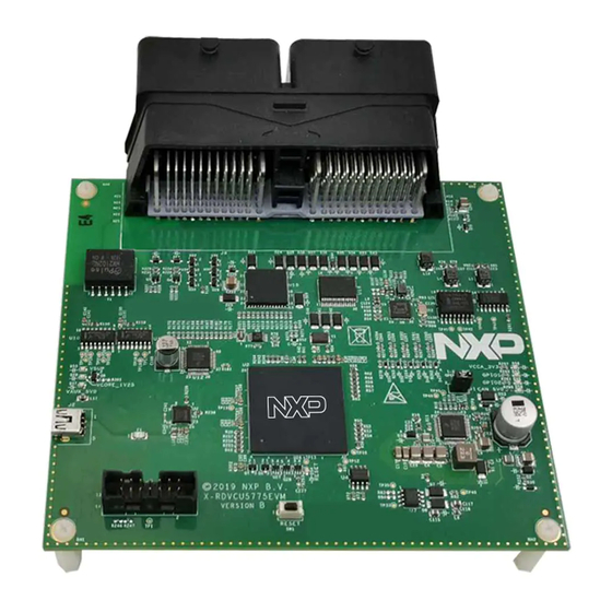
NXP Semiconductors Chapter 2 Hardware User Guide 2.1 Overview Figure 1. Master board MPC5775B BMS Plus VCU Reference Design User Guide, Rev. 0, February 2020 Supporting Information 4 / 47... - Page 5 • 3 x CAN interfaces, two is supported via NXP CANFD transceiver TJA1052 and TJA1145, another is supported via FS65xx. • 1 x LIN interface MC33662BLEF MPC5775B BMS Plus VCU Reference Design User Guide, Rev. 0, February 2020 Supporting Information 5 / 47...
- Page 6 2.3.1 Power SBC 2.3.1.1 Board power The MC33FS6523CAE provides a robust, scalable power management to the MPC5775B MCU with fail silent safety monitoring measures making it fit for ASIL-D. It consists of multiple switching and linear voltage regulators. When external power, typical 12 V automotive DC power supply with current limit > 600 mA, is applied to jumper J8 connector of master board.
- Page 7 The jumper J1 is used to configure the DEBUG mode of SBC, keep it onboard as shown in the following figure to activates the Debug mode. Once activated, there is no deep fail-safe state. MPC5775B BMS Plus VCU Reference Design User Guide, Rev. 0, February 2020 Supporting Information...
- Page 8 When the specific condition is reached, the SBC will reset MCU via SBC_RSTB pin. The following figure shows the board supports multiple MCU reset methods like SBC, JTAG and Switch Reset(SW1). Figure 5. Board reset circuit MPC5775B BMS Plus VCU Reference Design User Guide, Rev. 0, February 2020 Supporting Information 8 / 47...
- Page 9 In addition to the internal 16 MHz oscillator, the MCU can also be clocked by external oscillator (Y1). The clock circuitry for the 40 MHz crystal is shown in the following figure. The symbol named “DNP” indicates the device is not mounted to the PCB. MPC5775B BMS Plus VCU Reference Design User Guide, Rev. 0, February 2020 Supporting Information...
- Page 10 The USB to serial UART connection is shown in the following figure. Can connect to PC via mini USB to put string on screen or get string from screen by Serial Debug Assistant. MPC5775B BMS Plus VCU Reference Design User Guide, Rev. 0, February 2020 Supporting Information...
- Page 11 (AC20, AD20). TJA1045T/FD must be drove through DSPI. The SPI signal is transferred to the MCU through DSPI0 with CS2, MCU use the interface to configure the PHY. Figure 10. TJA1052i transceiver circuit MPC5775B BMS Plus VCU Reference Design User Guide, Rev. 0, February 2020 Supporting Information 11 / 47...
- Page 12 25 MHz external oscillator (Y2). The default physical address is configured as 0b00xx0 by the pull-down or pull-up resistor on the pin. A pair of differential signal(EPHY_TRX_P, EPHY_TRX_M) is routed to 130-pin ECU connector. MPC5775B BMS Plus VCU Reference Design User Guide, Rev. 0, February 2020 Supporting Information 12 / 47...
- Page 13 ADC input signal process circuit (as shown in the following figure). In addition to MCU_AIN4 channel supports external 0-12 V analog signal input from J8, other channels only support 0-5 V. MPC5775B BMS Plus VCU Reference Design User Guide, Rev. 0, February 2020 Supporting Information...
- Page 14 In addition to MCU_DIN4 and MCU_DIN5 channels support 0/12V digital signal input from J8, other channels only support 0/5V (as shown in the following figure). MPC5775B BMS Plus VCU Reference Design User Guide, Rev. 0, February 2020 Supporting Information 14 / 47...
- Page 15 As shown in the following figure, the master board enables SG0-SG9 as digital input, SP0-SP4 as analog input, these port is connect to J8, and MCU read switch status via DPSI2, analog signal via MSDI_AMUX through eQADC channel 0 (ANA0). MPC5775B BMS Plus VCU Reference Design User Guide, Rev. 0, February 2020 Supporting Information...
- Page 16 1/2. The user can use eMIOS mode Pulse width measurement mode to measure PWM signal, its amplitudes range from 3.3 V to 12 V. MPC5775B BMS Plus VCU Reference Design User Guide, Rev. 0, February 2020 Supporting Information 16 / 47...
- Page 17 MCU can configure DSPI2 with CS2 to control it, and also supports the direct control to the output pins (HS0-HS3) via the HSD_IN0-HSD_IN3 with GPIO. MPC5775B BMS Plus VCU Reference Design User Guide, Rev. 0, February 2020 Supporting Information 17 / 47...
- Page 18 The board has two TPL(U10, U11) routed three MCU DSPI, includes DSPI0 with CS0 for master, DSPI1 with CS0 for TPL1 slave, DSPI3 with CS0 for TPL2 slave. MPC5775B BMS Plus VCU Reference Design User Guide, Rev. 0, February 2020 Supporting Information...
- Page 19 GPIO(V25, V26) to simulate I C protocol. The default devices address is 0x51. Figure 21. RTC circuit MPC5775B BMS Plus VCU Reference Design User Guide, Rev. 0, February 2020 Supporting Information 19 / 47...
- Page 20 2.4 130 pin ECU connector There is a 130-pin ECU connector onboard, consisting of two parts of header M1 and M2. Figure 23. 130-pin ECU connector MPC5775B BMS Plus VCU Reference Design User Guide, Rev. 0, February 2020 Supporting Information 20 / 47...
- Page 21 Power supply Digital GND VBAT Power supply Digital GND Digital GND Digital GND Digital GND Digital GND Table continues on the next page... MPC5775B BMS Plus VCU Reference Design User Guide, Rev. 0, February 2020 Supporting Information 21 / 47...
- Page 22 Neutral gear switch input AGND Analog GND R_DIN EPHY_TRX_P Ethernet Differential Digital GND signal (+) Digital GND Digital GND Table continues on the next page... MPC5775B BMS Plus VCU Reference Design User Guide, Rev. 0, February 2020 Supporting Information 22 / 47...
- Page 23 LSD output 2 Not connected WATER_PUMP_ LSD output 1 Not connected RLY_DOUT DCDC_EN_DOU LSD output 0 Not connected Table continues on the next page... MPC5775B BMS Plus VCU Reference Design User Guide, Rev. 0, February 2020 Supporting Information 23 / 47...
- Page 24 HSD output 3 Not connected _DOUT HEAT_DRV_DO HSD output 1 Not connected PRECH_CTT_DO HSD output 2 Not connected MP_CTT_DOUT HSD output 0 Not connected MPC5775B BMS Plus VCU Reference Design User Guide, Rev. 0, February 2020 Supporting Information 24 / 47...
-
Page 25: Chapter 3 Software User Guide
There is an issue in SDK drivers source code. Please modify the macro named PIT_CLOCK_NAMES from MPC5775B_features.h header file in which SDK/platform/devices/ PITRTI0_CLK to PER_CLK in line 178 of the MPC5775B/include/. Figure 25. S32DS IDE MPC5775B BMS Plus VCU Reference Design User Guide, Rev. 0, February 2020 Supporting Information 25 / 47... - Page 26 Documentation contains automatically generated documents by S32DS. Table continues on the next page... MPC5775B BMS Plus VCU Reference Design User Guide, Rev. 0, February 2020 Supporting Information 26 / 47...
- Page 27 The following steps must be followed to download the exist elf file to MCU using S32DS. 1. Launch the S32DS IDE, click on the Flash icon, the Flash Configurations window appears. MPC5775B BMS Plus VCU Reference Design User Guide, Rev. 0, February 2020 Supporting Information...
- Page 28 2. Create a new configuration, adjust its name and browse for elf/srec/hex file. Figure 29. Create new configuration 3. Select MCU and specific core you are targeting. MPC5775B BMS Plus VCU Reference Design User Guide, Rev. 0, February 2020 Supporting Information 28 / 47...
- Page 29 BMS (50ms), VCU(10ms) , UDS(100ms) and BSP(300ms) tasks. The callback function of the system software timer is called every 10ms, and schedules multitasking in the timer callback. MPC5775B BMS Plus VCU Reference Design User Guide, Rev. 0, February 2020 Supporting Information...
- Page 30 • CAN Adaptor: PCAN-USB Pro. NOTE There is an issue in MCAL4.0. Please replace Adc_Eqadc.c with the provided one in fix folder to enable ADC calibration functions. MPC5775B BMS Plus VCU Reference Design User Guide, Rev. 0, February 2020 Supporting Information 30 / 47...
- Page 31 NXP Semiconductors Software User Guide Figure 33. EB tresos Figure 34. Lauterbach debugger MPC5775B BMS Plus VCU Reference Design User Guide, Rev. 0, February 2020 Supporting Information 31 / 47...
- Page 32 (startup, linker command files). Tresos contains the Tresos project with the application configuration. makefile is the MCAL sample application makefile. Table continues on the next page... MPC5775B BMS Plus VCU Reference Design User Guide, Rev. 0, February 2020 Supporting Information 32 / 47...
- Page 33 For downloading the exist elf file using TRACE32 follow these stps. 1. Launch the TRACE32. Select File > Run Script…, from the menu bar. MPC5775B BMS Plus VCU Reference Design User Guide, Rev. 0, February 2020 Supporting Information 33 / 47...
- Page 34 2. Select the script named run.cmm (in root directory) to download elf. file into flash. Figure 37. Browse script file 3. Click Go button to run. MPC5775B BMS Plus VCU Reference Design User Guide, Rev. 0, February 2020 Supporting Information 34 / 47...
- Page 35 1. Launch the EB tresos Studio and select File > Import, from the IDE menu. Choose import source page appears. Click Browse and select the project folder \Tresos\workspace, click Finish. MPC5775B BMS Plus VCU Reference Design User Guide, Rev. 0, February 2020 Supporting Information...
- Page 36 NXP Semiconductors Software User Guide Figure 39. Import projects 2. Double click the project name PDC_5775B_MCAL and click generate button. Figure 40. Generate code MPC5775B BMS Plus VCU Reference Design User Guide, Rev. 0, February 2020 Supporting Information 36 / 47...
- Page 37 6. You can run clear.bat to clear output objects in unexpected situations and build again. NOTE Recommended optimization option for this demo is -Osize if Green Hills compiler is used. MPC5775B BMS Plus VCU Reference Design User Guide, Rev. 0, February 2020 Supporting Information 37 / 47...
- Page 38 2. There is a limitation in ETH module. You need to install ETH_RxCbk callback into plugin codes to enable ETH receive function. a. Copy the following code into EthIf_RxIndication ETH_RxCbk(CtrlIdx, FrameType, IsBroadcast, PhysAddrPtr, DataPtr, LenByte) a. Include pdc_eth.h in EthIf_Cbk.c. MPC5775B BMS Plus VCU Reference Design User Guide, Rev. 0, February 2020 Supporting Information 38 / 47...
-
Page 39: Chapter 4 Gui User Guide
All BCC data are displayed on the BCCDATA page (the following figure), where the first row indicates the status of the CID, including OK, timeout, CRC, etc. The last four rows indicates BCC communication errors and BCC faults. MPC5775B BMS Plus VCU Reference Design User Guide, Rev. 0, February 2020 Supporting Information... - Page 40 NXP Semiconductors GUI user guide Figure 45. BCC data page MPC5775B BMS Plus VCU Reference Design User Guide, Rev. 0, February 2020 Supporting Information 40 / 47...
-
Page 41: Chapter 5 Bootloader User Guide
• Click Upload Firmware button and select the binary file to be transferred. • Select CRC-16(DNP) algorithm. • Click Calculate button to generate CRC value. MPC5775B BMS Plus VCU Reference Design User Guide, Rev. 0, February 2020 Supporting Information 41 / 47... - Page 42 Bootloader User Guide Figure 47. CRC-16(DNP) example 5. Edit configuration file can_uds.json in bootloader_bin folder: • Fill in the CRC value calculated in Step MPC5775B BMS Plus VCU Reference Design User Guide, Rev. 0, February 2020 Supporting Information 42 / 47...
- Page 43 Figure 48. CRC in can_uds.json example • Fill in the correct paths of MPC577XX_flash_drv.bin and app.bin (here PDC_5775B_MCAL.bin). Figure 49. Path of MPC577XX_flash_drv.bin example MPC5775B BMS Plus VCU Reference Design User Guide, Rev. 0, February 2020 Supporting Information 43 / 47...
- Page 44 • Select and fill values as shown below and then click Connect button. Note that target address and source address are fixed as 0x55 and 0x35. MPC5775B BMS Plus VCU Reference Design User Guide, Rev. 0, February 2020 Supporting Information...
- Page 45 NXP Semiconductors Bootloader User Guide Figure 51. Parameters for connecting device MPC5775B BMS Plus VCU Reference Design User Guide, Rev. 0, February 2020 Supporting Information 45 / 47...
- Page 46 • Wait the process to succeed. • You can repeat Step 4, 5 and 8 to download apps through bootloader again. Figure 53. Table properties window MPC5775B BMS Plus VCU Reference Design User Guide, Rev. 0, February 2020 Supporting Information 46 / 47...
- Page 47 How To Reach Us Information in this document is provided solely to enable system and software implementers to use NXP products. There are no express or implied copyright licenses granted hereunder to Home Page: design or fabricate any integrated circuits based on the information in this document. NXP nxp.com reserves the right to make changes without further notice to any products herein.
- Page 48 Mouser Electronics Authorized Distributor Click to View Pricing, Inventory, Delivery & Lifecycle Information: RDVCU5775EVM...
Need help?
Do you have a question about the MPC5775B and is the answer not in the manual?
Questions and answers