Table of Contents
Advertisement
Quick Links
Advertisement
Table of Contents

Related Manuals for Beckhoff AA3000


Summary of Contents for Beckhoff AA3000
- Page 1 Operating instructions | EN AA3000 Electric cylinders 2023-07-04 | Version 2.0...
-
Page 3: Table Of Contents
1.2 Version numbers ........................... 1.3 Staff qualification........................... 1.4 Safety and instruction..........................11 1.5 Explanation of symbols ......................... 11 1.6 Beckhoff Services ..........................13 1.6.1 Support services ........................13 1.6.2 Training offerings ........................13 1.6.3 Service offerings ........................13 1.6.4 Headquarters Germany ......................14 1.6.5 Downloadfinder .......................... - Page 4 10.3 During operation............................ 62 10.4 After operation............................63 11 Maintenance and cleaning.......................... 64 11.1 Maintenance............................64 11.2 Maintenance intervals ........................... 65 11.3 Lubrication of the spindle drive ......................66 11.4 Cleaning ..............................68 12 Accessories ..............................70 ─── AA3000 Version: 2.0...
- Page 5 14.2.1 Returning to the vendor ......................76 15 Guidelines and Standards .......................... 77 15.1 Standards.............................. 77 15.2 Guidelines ............................. 77 15.3 Test centers ............................77 15.4 EU conformity............................78 15.5 CCC conformity............................. 78 Index ................................79 Version: 2.0 AA3000 ───...
-
Page 6: Documentation Notes
Documentation notes Documentation notes Disclaimer Beckhoff products are subject to continuous further development. We reserve the right to revise the documentation at any time and without notice. No claims for the modification of products that have already been supplied may be made on the basis of the data, dia- grams, and descriptions in this documentation. -
Page 7: Limitation Of Liability
• Use of untrained personnel • Use of unauthorized spare parts 1.1.4 Copyright © Beckhoff Automation GmbH & Co. KG, Germany The copying, distribution and utilization of this document as well as the communication of its contents to others without express autho- rization is prohibited. -
Page 8: Version Numbers
German original. Product features The valid product features are always those specified in the current documentation. Further information given on the product pages of the Beckhoff homepage, in emails or in other publications is not au- thoritative. ─── AA3000... -
Page 9: Staff Qualification
Trained specialists have received specific technical training and have specific technical knowledge and experience. Trained special- ists can: • apply relevant standards and directives • assess tasks that they have been assigned • recognize possible hazards • prepare and set up workplaces Version: 2.0 AA3000 ───... - Page 10 They are familiar with relevant standards and directives. Quali- fied electricians can: • independently recognize, avoid and eliminate sources of danger • implement specifications from the accident prevention regula- tions • assess the work environment • independently optimize and carry out their work ─── AA3000 Version: 2.0...
-
Page 11: Safety And Instruction
DANGER Failure to observe will result in serious or fatal injuries. WARNING Failure to observe may result in serious or fatal injuries. CAUTION Failure to observe may result in minor or moderate injuries. Version: 2.0 AA3000 ───... - Page 12 In the case of documentation on a monitor screen, use the zoom function to enlarge the QR code and reduce the distance. ─── AA3000 Version: 2.0...
-
Page 13: Beckhoff Services
1.6.1 Support services Beckhoff Support offers technical advice on the use of individual Beckhoff products and system planning. Our support engineers offer you competent assistance, for comprehension questions as well as for commissioning. -
Page 14: Headquarters Germany
Documentation notes 1.6.4 Headquarters Germany Beckhoff Automation GmbH & Co. KG Hülshorstweg 20 33415 Verl, Germany +49 5246 963-0 info@beckhoff.com www.beckhoff.com/en-en/ A detailed overview of our worldwide locations can be found online at Global presence. www.beckhoff.com/en-en/company/global-presence/ 1.6.5 Downloadfinder Our download finder contains all the files we offer for download: from our application reports to our technical documentation and con- figuration files. -
Page 15: For Your Safety
Safety pictograms You will find safety symbols on Beckhoff products and packaging. The symbols may be glued, printed, or lasered on and may vary de- pending on the product. They serve to protect people and to prevent damage to the products. -
Page 16: General Safety Instructions
Observe tightening torques Mount and repeatedly check connections and components, comply- ing with the prescribed tightening torques. Use the original packaging only When shipping, transporting, storing and packing, use the original packaging or non-conductive materials. ─── AA3000 Version: 2.0... -
Page 17: During Operation
Secure the machine or plant against being in- advertently started up. Observe the chapter "Decommissioning", [Page 75]. No direct skin contact with solvents or lubricants In case of improper use, the solvents or lubricants used can lead to skin irritations. Avoid direct skin contact. Version: 2.0 AA3000 ───... -
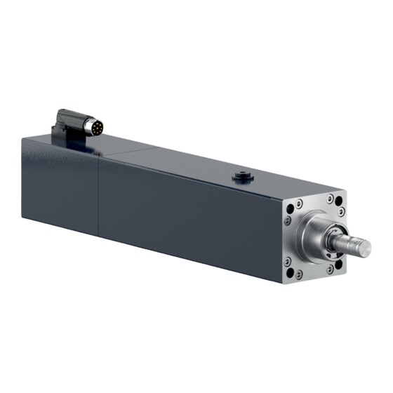
Page 18: Product Overview
Product overview Product overview Item number Explanation Spindle end Threaded holes for mounting Bleeding Screw plug lubrication Power box Safety pictograms Identification plate Housing ─── AA3000 Version: 2.0... -
Page 19: Name Plate
Product number Continuous force Nominal velocity Standstill current Nominal voltage Nominal output Insulation class Protection class Brake type Safety Integrity Level Beckhoff Traceability Number (BTN) DataMatrix code Additional information standard CE conformity WEEE compliance Country of manufacture Version: 2.0 AA3000 ───... -
Page 20: Type Key
3 = 200 mm 4 = 250 mm Feedback system H = OCT, 24 bit, SIL 2 capable, multi-turn absolute encoder Holding brake 0 = without holding brake 1 = 24 V DC holding brake 0000 Versions 0000 = standard 1xxx = special version ─── AA3000 Version: 2.0... -
Page 21: Product Characteristics
Electronic identification plate The electronic identification plate contains all specific data of the drive and can be read directly from the Beckhoff drive system for au- tomatic parameterization. ISO 15552 compatible The dimensions and mounting points of the AA3000 electric cylinder are designed to be compatible with the standard ISO 15552 cylin- ders for pneumatic cylinders. -
Page 22: Ordering Options
• Provide for external end positions or stay within the stroke of the spindle. • Perform homing and use the NC end positions to prevent pos- sible damage to the spindle drive. • Read the chapter "Commissioning", [Page 61] before execut- ing homing. ─── AA3000 Version: 2.0... -
Page 23: Holding Brake [+]
This means that the encoder cannot detect the current spindle position and hom- ing must be performed before restarting. Further information can be found in chapter "Commissioning", [Page 57]. Version: 2.0 AA3000 ───... -
Page 24: Intended Use
Any type of use that exceeds the permissible values from the techni- cal data is regarded as inappropriate and is thus prohibited. Non-approved areas of application The electric cylinders from the AA3000 series are not suitable for use in the following areas: • Hazardous areas •... -
Page 25: Technical Data
S1 and depends on the external load applied. Force constant k [N/A Indication of how much force the motor generates per ampere with the standstill current. The following applies: F = I x k 0 0 Version: 2.0 AA3000 ───... -
Page 26: Data For Operation And Environment
When this threshold is exceeded, the software switches off the electric cylinder. Data for operation and environment Beckhoff products are designed for operation under certain environ- mental conditions, which vary according to the product. The follow- ing specifications must be observed for operation and environment in order to achieve the optimum service life of the products. -
Page 27: General Housing Properties
Switch-off temperature 140°C The temperature evaluation is executed via the encoder by convert- ing the resistance value into a temperature and making it available to the downstream electronics. This temperature is referenced for the switching thresholds. Version: 2.0 AA3000 ───... -
Page 28: Power Derating
Calculation of the power reduc- Ambient temperature and installation altitude tion Calculation of the power data when exceeding the specified limits: Ambient temperature > 40°C and installation altitude > 1000 m above sea level: CA_red ─── AA3000 Version: 2.0... -
Page 29: Size Aa3023
58 x 58 Drilling pattern threaded holes for 38 x 38 38 x 38 38 x 38 38 x 38 mounting [mm] Thread dimension spindle end M12 x 1.25 M12 x 1.25 M12 x 1.25 M12 x 1.25 Version: 2.0 AA3000 ───... -
Page 30: Service Life Aa3023
For more information, see the chapters "Maintenance intervals", [Page 65] and "Spindle end", [Page 46]. 6875 6250 5625 5000 4375 3750 3125 2500 1875 1250 1000 10000 100000 Service life [km] Curve Electric cylinder Lead p [mm] AA3023-w2Hz-0000 AA3023-w2Hz-0000 ─── AA3000 Version: 2.0... -
Page 31: Dimensional Drawing Aa3023
Technical data 4.3.2 Dimensional drawing AA3023 All figures in millimeters Illustration: Perspective view Illustration: Front view Illustration: Side view A and B to show flange dimensions Version: 2.0 AA3000 ───... -
Page 32: Size Aa3033
75 x 75 Drilling pattern threaded holes for 56.5 x 56.5 56.5 x 56.5 56.5 x 56.5 56.5 x 56.5 mounting [mm] Thread dimension spindle end M16 x 1.5 M16 x 1.5 M16 x 1.5 M16 x 1.5 ─── AA3000 Version: 2.0... -
Page 33: Service Life Aa3033
For more information, see the chapters "Maintenance intervals", [Page 65] and "Spindle end", [Page 46]. 13750 12500 11250 10000 8750 7500 6250 5000 3750 2500 1250 1000 10000 100000 Service life [km] Curve Electric cylinder Lead p [mm] AA3033-w3Hz-0000 AA3033-w3Hz-0000 Version: 2.0 AA3000 ───... -
Page 34: Dimensional Drawing Aa3033
Technical data 4.4.2 Dimensional drawing AA3033 All figures in millimeters Illustration: Perspective view Illustration: Front view Illustration: Side view A and B to show flange dimensions ─── AA3000 Version: 2.0... -
Page 35: Size Aa3053
89 x 89 89 x 89 89 x 89 89 x 89 89 x 89 mounting [mm] Thread dimension spindle end M20 x 1.5 M20 x 1.5 M20 x 1.5 M20 x 1.5 M20 x 1.5 Version: 2.0 AA3000 ───... -
Page 36: Service Life Aa3053
For more information, see the chapters "Maintenance intervals", [Page 65] and "Spindle end", [Page 46]. 27500 25000 22500 20000 17500 15000 12500 10000 7500 5000 2500 1000 10000 100000 Service life [km] Curve Electric cylinder Lead p [mm] AA3053-w4Hz-0000 AA3053-w4Hz-0000 AA3053-w4Hz-0000 ─── AA3000 Version: 2.0... -
Page 37: Dimensional Drawing Aa3053
Technical data 4.5.2 Dimensional drawing AA3053 All figures in millimeters Illustration: Perspective view Illustration: Front view Illustration: Side view A and B to show flange dimensions Version: 2.0 AA3000 ───... -
Page 38: Scope Of Supply
Check your delivery for completeness. If any parts are missing or became damaged during transport, contact the carrier, vendor or our service department immediately. Check the shipment for the following contents: • Electric cylinders from the AA3000 series • Short information Packaging Instructions for handling are printed on the packaging:... -
Page 39: Transport And Storage
• Observe the maximum stacking height. Maximum stacking height The table shows the maximum stacking height at which you may store and transport the product in its original packaging on a pallet: Size Stacking height [pieces] AA3023 AA3033 AA3053 Version: 2.0 AA3000 ───... -
Page 40: Transport
• Transport electric cylinder in horizontal position • Transport electric cylinder size AA3053 with at least two eye- bolts. Legal regulations for the lifting of loads When transporting electric cylinders, comply with the legal regula- tions on lifting loads for employees. ─── AA3000 Version: 2.0... -
Page 41: Transport Aa3023 And Aa3033
The mounting holes on the flange side can be used as attachment points. Only use suitable and sufficiently dimensioned lifting equipment. ► Screw an eyebolt [1] into one of the four holes on the A-flange of the electric cylinder. Version: 2.0 AA3000 ───... -
Page 42: Long-Term Storage
For more information, see chapter "Transportation and stor- age", [Page 39]. In the original packaging, the electric cylinder is protected against chemical and aggressive substances within the scope of classes 1C2 (chemical substances) and 1B2 (biological conditions). Ensure the storage space is vibration-free. ─── AA3000 Version: 2.0... -
Page 43: Technical Description
[Page 66]. • Protect the application from contamination by means of addi- tional attachments (e.g. bellows) or design measures. The standard installation position of the electric cylinders is the de- sign IM B5 and IM V1 according to DIN EN 60034-7. Version: 2.0 AA3000 ───... - Page 44 • Mechanical safeguards or interlocks • Attachment of a weight counterbalance Permanent magnet holding brakes alone are not approved for the protection of persons. In line with ISO 13849-1 and ISO 13849-2, additional precautions must be taken for personal protection. ─── AA3000 Version: 2.0...
-
Page 45: Temperature Sensor Lptc-600
Technical description Temperature sensor LPTC-600 The temperature sensor LPTC-600 is installed in all electric cylin- ders of the AA3000 series. The LPTC-600 is integrated in the monitoring system of the servo drive when using the pre-assembled power cable. Configure the servo drive according to the motor temperature warning at 120°C... -
Page 46: Spindle End
Preferred backlash-free coupling elements • Quick coupling with radial misalignment compensation • Compensating coupling with five degrees of freedom, for trans- mission of axial forces ─── AA3000 Version: 2.0... -
Page 47: Mechanical Installation
The following table shows the screw size and the corresponding screw depths and tightening torques. Size AA3023 AA3033 AA3053 Hexagon socket head cap screw DIN EN ISO 4762–8.8 A-flange screw depth [mm] B-flange screw depth [mm] Tightening torque [Nm] Version: 2.0 AA3000 ───... -
Page 48: Fastening The End Of The Spindle
Size AA3023 AA3033 AA3053 External thread at spindle end M12 x 1.25 M16 x 1.5 M20 x 1.5 available thread length [mm] Width across flats ─── AA3000 Version: 2.0... - Page 49 Mounting accessories on the spindle end This example shows the mounting of a rod end on the spindle. ► Hold the spindle [1] with a suitable tool [2] at the wrench flat pro- vided for this purpose while mounting the respective acces- sories [3]. Version: 2.0 AA3000 ───...
-
Page 50: Electrical Installation
The type of power box depends on the size or peak current of the electric cylinder. Size Power box ® AA3023 rotatable angle box itec ® AA3033 rotatable angle box itec ® AA3053 rotatable angle box M23-speedtec ─── AA3000 Version: 2.0... -
Page 51: Pin Assignment Itec® (Oct)
Motor phase U black/1 Motor phase V black/2 Motor phase W black/3 green-yellow Temperature-/OCT- blue Shield Shield Illustration: rotatable angle box ® M23-speedtec (OCT) Brake+ black/5 Temperature+/OCT+ white Brake- black/6 Illustration: Mating face power box ® M23-speedtec (OCT) Version: 2.0 AA3000 ───... -
Page 52: Connect The Motor Cable
• Check connector for damage and replace if necessary Trouble-free application and assembly • Wire in accordance with the applicable regulations and stan- dards. • Use pre-assembled and shielded cables according to the servo drive used. ─── AA3000 Version: 2.0... -
Page 53: Establish The Itec® Plug Connection
If the itec® connector does not automatically lock into place on the power box during the rotational movement: ® ► Turn the bayonet lock [1] of the itec connector of the motor ca- ble by hand to the correct position until the marking points are in line. Version: 2.0 AA3000 ───... -
Page 54: Establish The M23-Speedtec® Connector
► Turn the cap nut of the connector [1] to the right by hand. ► Make sure that the lettering “open” [1] and the marking point [1] on the connector [1] are in line with the marking elements [2] of the power box. ® The M23-speedtec connector is correctly connected. ─── AA3000 Version: 2.0... -
Page 55: Select Motor Cables
Torsion-capable Motor cables for AX8000 multi-axis servo system Servo drive Ordering information Laying method AX8108 and AX8206 ZK4800-8003-xxxx Fixed installation ZK4800-8023-xxxx Highly dynamic ZK4800-8063-xxxx Torsion-capable AX8118 and AX8525 ZK4800-8004-xxxx Fixed installation ZK4800-8024-xxxx Highly dynamic ZK4800-8064-xxxx Torsion-capable Version: 2.0 AA3000 ───... -
Page 56: Select Extension Cable
Torsion-capable installation Motor cable Motor cable Ordering information AX5000 AX8000 of the extension ca- ZK4500-8062-xxxx ZK4800-8062-xxxx ZK4501-8062-xxxx ZK4500-8063-xxxx ZK4800-8063-xxxx ZK4501-8063-xxxx ZK4500-8064-xxxx ZK4800-8064-xxxx ZK4501-8064-xxxx Connect the extension cable as described in chapter "Connect the motor cable", [Page 52]. ─── AA3000 Version: 2.0... -
Page 57: Commissioning
The commissioning described here includes the products • TwinCAT 3 Drive Manager 2 • AX8000 multi-axis servo system • AA3000 electric cylinder 10.1 Before commissioning Pay attention to the following points before commissioning: ► Read the operating instructions of the servo drives used ►... -
Page 58: System Requirements
• Check the firmware version of the servo drive • Update to the required version TE5950 setup download You can find the current setup file on the product website TE5950 | TwinCAT 3 Drive Manager 2 ─── AA3000 Version: 2.0... -
Page 59: Mechanical And Electrical Requirements
► If the holding brake releases, continue commissioning. ► If the holding brake does not release, the brake fault must be corrected before further commissioning. Further information can be found in chapter "Fault correction", [Page 71]. ► Ensure holding torque of the brake Version: 2.0 AA3000 ───... -
Page 60: During Commissioning
► Check the use and value of the NC end positions. The screen- shot shows an example of the parameter that contains the end position values transferred to the NC. ► Check the condition of the plant and activate the project ─── AA3000 Version: 2.0... -
Page 61: Electric Cylinder Without Integrated Anti-Twist Protection [+]
"Technical data", [Page 25]. ► The dimensions for determining the zero position of the spindle can be found at "Dimensional drawing AA3023", [Page 31], "Di- mensional drawing AA3033", [Page 34] and "for the AA3053", [Page 37]. Version: 2.0 AA3000 ───... -
Page 62: During Operation
• Perform a complete lubrication stroke every 250,000 cycles. • Shorten the maintenance interval if necessary. Further information can be found in chapter "Lubrication of the spin- dle drive", [Page 66]. ─── AA3000 Version: 2.0... -
Page 63: After Operation
• Make sure that the electric cylinder comes to a complete stop. • Establish that the machine or equipment is in a safe state. • Take into account the installation position of the electric cylin- der. Further information can be found in chapter "Installation position", [Page 43] . Version: 2.0 AA3000 ───... -
Page 64: Maintenance And Cleaning
• For maintenance work, bring the connected electric cylinders and the machine into a safe state. • De-energize the connected electric cylinders and the machine. • Secure the connected electric cylinders and the machine against unauthorized restarting. ─── AA3000 Version: 2.0... -
Page 65: Maintenance Intervals
As the volume increases: Check electric cylinder for increased phase current and winding temperature Do not continue to operate electric cylinder Contact Beckhoff Service Ball screw 1 million cycles Lubricate the spindle drive. See chapter "Lubrication of the spindle drive", [Page 66]. -
Page 66: Lubrication Of The Spindle Drive
Lubricant Beckhoff recommends that Klüberlub BE 71-501 lubricant be used. For more information on the lubricant, please contact the manufac- turer. Lubrication position and lubri- The approachable lubrication position is reached according to the distance in the following table. - Page 67 ► Observe the tightening torques: Component Specification Tightening torque [Nm] Screw [1] DIN 908 M10x1 ► Run lubrication stroke three times according to size Further information can be found in chapter "Lubrication of the spin- dle drive", [Page 66] . Version: 2.0 AA3000 ───...
-
Page 68: Cleaning
Use grease-dissolving and non-aggressive cleaning agents for cleaning. Isopropanol cleaning agent can be used for cleaning. Non-approved cleaning agents: Non-approved cleaning agents Chemical formula Aniline hydrochloride Bromine Sodium hypochlorite; bleaching solution NaCIO Mercury (II) chloride HgCl Hydrochloric acid ─── AA3000 Version: 2.0... - Page 69 • Do not use any cleaning agents that may adhere to the spindle thread and enter the electric cylinder or the spindle nut during the working stroke. • In the case of vertical installation, ensure that there is no clean- ing agent on the cylinder opening. Version: 2.0 AA3000 ───...
-
Page 70: Accessories
Electric cylinder AA3023 AA3033 AA3053 Pneumatic cylinder [mm] Ø 40 Ø 63 Ø 100 To attach the accessories to the electric cylinder, follow the installa- tion instructions in the chapter "Fastening the end of the spindle", [Page 48]. ─── AA3000 Version: 2.0... -
Page 71: Fault Correction
Noises during operation High temperature at idling speed High temperature under load Untrue running behavior 10 11 Grinding noises Brake fault 13 14 Output stage fault 15 16 Feedback error 17 18 Lack of braking effect Version: 2.0 AA3000 ───... - Page 72 Power connector not fitted correctly Check the connectors on the power connector and on the electric cylinder Interruption in the feedback line or motor cable Check cables for wire break or crushing. Re- place defective cables, then measure and check. ─── AA3000 Version: 2.0...
- Page 73 Rotating parts chafing on the housing or electric Inspect chafing parts and readjust if necessary cylinder components Defective bearings; irreparable bearing damage Send in electric cylinder. The repair is carried out by the vendor. Version: 2.0 AA3000 ───...
- Page 74 Service if necessary tric cylinder Check spindle surface for damage and contamina- Contact Beckhoff Service, avoid impacts on tion the spindle and sudden loads during operation and assembly ───...
-
Page 75: Decommissioning
Accidental machine movements can lead to serious or fatal in- juries. Do not remove components from the products Only Beckhoff Automation GmbH & Co. KG is permitted to remove com- ponents. Contact Beckhoff Service for further information. Removal of the electric cylinder from the machine ►... -
Page 76: Disposal
In accordance with the WEEE-2012/19/EU directives, you can return used devices and accessories for professional disposal. The trans- port costs are borne by the sender. Send the used devices with the note "For disposal" to: Beckhoff Automation GmbH & Co. KG "Service" Building Stahlstrasse 31 D-33415 Verl... -
Page 77: Guidelines And Standards
15.3 Test centers The electric cylinders do not fall within the scope of the Machinery Directive. However, Beckhoff products are designed and eval- uated in full compliance with all relevant regulations for personal safety and use in a machine or system. -
Page 78: Eu Conformity
Guidelines and Standards 15.4 EU conformity Provision Beckhoff Automation GmbH & Co KG will be pleased to provide you with EU declarations of conformity and manufacturer's declarations for all products on request. Please send your request to: info@beckhoff.com 15.5 CCC conformity... -
Page 79: Index
Technical data 26 Intended use 24 Tightening torques itec® connector Flange 41, 47 Connection 53 Transport 39 Label, see Safety symbols 15 Lubricant 66 Lubrication 66 Maintenance 64 Intervals 65 21 Operating Conditions 26 Ordering options 22 Version: 2.0 AA3000 ───... - Page 81 More Information: www.beckhoff.com/aa3000 Beckhoff Automation GmbH & Co. KG Hülshorstweg 20 33415 Verl Germany Phone: +49 5246 9630 info@beckhoff.com www.beckhoff.com...
Need help?
Do you have a question about the AA3000 and is the answer not in the manual?
Questions and answers