Advertisement
Quick Links
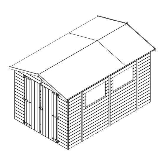
SANCTUARY I SHED - 2.4m x 3.6m
All dimensions are approximate and subject to the limitations of the materials used and the methods of manufacture
Manufacturer:
Dunster House Ltd.
Caxton Road
Bedford
Bedfordshire
England
MK41 0LF
(8ft x 12ft)
H4-2436SSH
Installation Manual
Please read this installation manual carefully
before proceeding with the construction of your shed.
Important!
Unique Shed Reference Number
_____________________________
V1
Customer Service:
cs@dunsterhouse.co.uk
www.dunsterhouse.co.uk
Advertisement

Related Manuals for Dunster House H4-2436SSH


Summary of Contents for Dunster House H4-2436SSH
- Page 1 Please read this installation manual carefully before proceeding with the construction of your shed. Important! All dimensions are approximate and subject to the limitations of the materials used and the methods of manufacture Manufacturer: Dunster House Ltd. Caxton Road Bedford Unique Shed Reference Number Bedfordshire...
- Page 2 In the unlikely event that you need to contact us, please do so in writing to: Email: cs@dunsterhouse.co.uk Post: FAO Customer Services, Dunster House Ltd - Factory 1, Caxton Road, Bedford, MK41 0LF Our Customer Services department is open 9:00 - 17:00, Monday to Friday. Please include your Sales Order number starting with SO or your postcode so we can locate your order.
- Page 3 Should you discover a rip or tear, the best course of action is to replace it immediately. At Dunster House, we sell high-grade mineral felt. More information on replacing the shed's roof material can be found here:...
-
Page 4: Pack Contents
Pack Contents PANEL EA - A - 1100x2194 PANEL CC - A - 1100x2194 PANEL EA - B - 1100x2194 PANEL CC - B - 1100x2194 PANEL AH - 1150x1897 PANEL BG - C - 1150x1897 PANEL BG - B - 550x1897 PANEL BM - B - 550x1897 PANEL FD - 725x1770 - DOUBLE DOOR LEAD MFP - 1220x1220x10... - Page 5 Pack Contents ST-PT1670120 ST-PT35351210 - L = 1210mm ST-PT35351795 - L = 1795mm ST-PT35351875 - L = 1875mm ST-PT35352130 - L = 2130mm 12x ST-PT35352200 - L = 2200mm 10x ST-PT35701120.75.75 - L = 1120mm ST-PT1945310 - L = 310mm ST-PT19451855 - L = 1855mm ST-PT19452145 - L = 2145mm ST-PT35701280.15.15.A - L = 1280mm...
- Page 6 Panels Layout OPTION 1 PANEL CC - B PANEL BM - B PANEL CC - A PANEL AH PANEL BG - B PANEL BG - B PANEL EA - A FRONT PANEL BG - C PANEL EA - B PANEL BM - B H4 - PANEL CC - B H4 - PANEL BM - B OPTION 2...
- Page 7 Assembly Steps Pre-drill parts before fixing with screws STEP 1: PANELS Items: PANEL AH - 1150x1897 Principle of connecting panels PANEL BG - C - 1150x1897 PANEL BG - B - 550x1897 1a) Line up the panels so that the top and bottom of each panel is PANEL BM - B - 550x1897 flush with one another.
- Page 8 Assembly Steps Pre-drill parts before fixing with screws STEP 2: BEARERS Items: 2a) Ensure the base is level. Space bearers at the specified 12x ST-PT35352200 (BEARER) distance as shown in the the diagram below (1.0). If the bearer MFP - 2200x1220x10 layout consists of double bearers, use 50mm screws to secure them MFP - 2200x960x10 as shown in the image to the right (1.1)
- Page 9 Assembly Steps Pre-drill parts before fixing with screws STEP 3: PANELS Items: PANEL CC - 2200x2194 (FRONT PANEL) PANEL EA - 2200x2194 (REAR PANEL) PANEL BM - B / BG - B / BG - C (SIDE PANEL WITH WINDOW) PANEL BM - B / BG - B / AH (SIDE PANEL WITHOUT WINDOW) 33x 50mm SCREW 25x 70mm SCREW...
- Page 10 Assembly Steps Pre-drill parts before fixing with screws STEP 4: RAFTER SUPPORTS Items: 4a) Position rafter supports on the side panels as is shown on the ST-PT35351210 (RAFTER SUPPORT) diagram. 50mm SCREW 4b) Connect rafter supports to the panel frame by using 2x 50mm screws per each support.
- Page 11 Assembly Steps Pre-drill parts before fixing with screws STEP 6: ROOF BOARDS 6a) Position the MFP as shown in the diagram below (1.0) with an over Items: hang of approximately 65mm. MFP - 1220x1220x10 MFP - 2440x1220x10 6b) Use 4x 35mm screws per each side to secure the MFP to the rafters and 64x 35mm SCREW front and rear panels.
- Page 12 Assembly Steps Pre-drill parts before fixing with screws STEP 7: HINGES Items: 7a) Position the lead door in the frame ensuring there is a 5mm gap on each side of the door. The bottom edge of the door should be flush with the bottom shiplap. See PANEL - FD (Lead) image below for reference (1.0).
- Page 13 Assembly Steps Pre-drill parts before fixing with screws STEP 9: CORNER TRIM 9a) Position the timber trims in each corner of the shed, as shown in the diagram Items: below. Make sure that the end of trim is flush with the bottom wall shiplap. ST-PT15151860 (Corner trim) 40x 30mm Nail 9b) Fix each corner trim into both panels.
- Page 14 Assembly Steps Pre-drill parts before fixing with screws STEP 10: WIND BRACE 10a) Position the wind braces as shown in the diagram below. Make sure that Items: they are flush with edge of the roof board. ST-PT35351210 (FRONT & REAR) ST-PT35351795 (SIDE) 10b) Fix each wind brace by using 35mm screws.
- Page 15 Assembly Steps Pre-drill parts before fixing with screws STEP 12: FASCIA BOARD AND DIAMOND FINIAL 12a) Position the fascia boards to the correct position as shown in the Items: diagram below. Fascia boards should overhang the roof boards by 10mm. ST-PT16701275.75.75 (Fascia board) Fix each fascia board to the wind brace by using 3x 35mm screws.
- Page 16 Assembly Steps Pre-drill parts before fixing with screws STEP 14: WINDOW SILL Items: 14a) Place the window sill on the bottom of window on outside ST-PT2535835 (WINDOW SILL) surface of glass. 50mm SCREW 14b) Use 50mm screws to secure the sill to the frame. Ensure the screws are 50mm from both ends of the window sill and equally spaced.
Need help?
Do you have a question about the H4-2436SSH and is the answer not in the manual?
Questions and answers