Advertisement
Quick Links
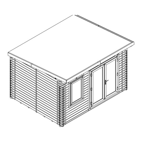
TERMINATOR 3.8m x 3.0m (62mm) Warmalog
E10-3830TWLPVC-62
Installation Manual
Please read this installation manual carefully
before proceeding with the construction of your log cabin.
Check all components prior to assembly
If you have purchased a log cabin with an extension please refer to the extension manual set
Important!
All dimensions are approximate and subject to the limitations of the materials used and the methods of manufacture
Unique Cabin Reference Number
Construction videos link
_____________________________
www.dunsterhouse.co.uk
Advertisement

Related Manuals for Dunster House TERMINATOR E10-3830TWLPVC-62


Summary of Contents for Dunster House TERMINATOR E10-3830TWLPVC-62
- Page 1 TERMINATOR 3.8m x 3.0m (62mm) Warmalog E10-3830TWLPVC-62 Installation Manual Please read this installation manual carefully before proceeding with the construction of your log cabin. Check all components prior to assembly If you have purchased a log cabin with an extension please refer to the extension manual set Important! All dimensions are approximate and subject to the limitations of the materials used and the methods of manufacture Unique Cabin Reference Number...
-
Page 2: Parts List
Side - Left & Right Door Frame 1865 19x22x1595 GT Gasket Trim 1595 19x22x1865 GT Gasket Trim 1865 Metal Logo Plate Dunster House C/sk Screw 70mm C/sk Screw 70mm C/sk Screw 35mm C/sk Screw 35mm C/sk Screw 20mm C/sk Screw 20mm WARMALOG WINDOW (62mm) - Page 3 Parts List Page 3 (Sheet 2 of 2) INSULATED FLOOR PANELS THK_mm WIDTH_mm LNG_mm PART NUMBER DESCRIPTION WLC-IFP-50x1200x2400 Floor Panel 1200 2400 WLC-IFP-50x1135x2400 Floor Panel 1135 2400 WLC-IFP-50x325x1765.A Floor Panel 1765 INSULATED ROOF PANELS PART NUMBER DESCRIPTION THK_mm WIDTH_mm LNG_mm WLC-RP-40x1200x2400.C Roof Panel 1200...
- Page 4 • Dunster House Ltd will not freely replace any parts that are damaged due to any neglectful workmanship when your cabin is being built. However, replacement parts are available to purchase, please contact our Parts department at parts@dunsterhouse.co.uk.
- Page 5 If you are still unable to find an answer to your query please contact our Customer Services department by email or in writing stating your query and including your order number starting with "SO" or your postcode to either: cs@dunsterhouse.co.uk or FAO Customer Services, Dunster House Ltd - Factory 1, Elms Farm Industrial Estate, Bedford, MK41 0LF Assembly Instruction Instructions are available from our website - https://dunsterhouse.co.uk/customer-login-area/log-in.
- Page 6 Page 6 How to install twisted/warped timber Timber is a natural product and unlike extrusions made from plastic or metal is likely to twist due to the nature of the material. Warped timber is unavoidable particularly with soft wood and is more common in longer and larger sections. Warping can occur even once a product is packed.
- Page 7 Identifying Wall Logs Page 7 There are different kinds of wall logs included in the pack. It is important to identify them correctly to avoid problems with the assembly. BOTTOM WALL LOG (WLC-BL) - Solid wood INSULATED WALL LOG (WLC-IWL) - Wall log with wall log, three tongues at the top, flat at the insulation inside, three tongues at the top, four tongues at bottom, first layer of wall logs, typically at the...
- Page 8 Component List Page 8 BEARERS BOTTOM WALL LOG Pressure Treated ITEM QTY PART NUMBER THK_mm WIDTH_mm LNG_mm DESCRIPTION Bearer (Pressure Treated) ITEM QTY THK_mm WIDTH_mm LNG_mm WLC-B-3660 3660 PART NUMBER DESCRIPTION Bearer (Pressure Treated) Bottom Wall Log WLC-B-415 WLC-BL-3800-DN 3800 INSULATED WALL LOG INSULATED WALL LOG ITEM QTY...
-
Page 9: Component List
Component List Page 9 PURLIN LOG ITEM QTY PART NUMBER DESCRIPTION THK_mm WIDTH_mm LNG_mm Purlin Log WLC-PL-3800-DNTM.3-5 3800 PURLIN LOG ITEM QTY THK_mm WIDTH_mm LNG_mm PART NUMBER DESCRIPTION WLC-PL-3800-DN.3-5 Purlin Log 3800 PURLIN LOG ITEM QTY THK_mm WIDTH_mm LNG_mm PART NUMBER DESCRIPTION Purlin Log WLC-PL-3310-NN.2-5... - Page 10 Component List Page 10 INSULATED FLOOR PANEL INSULATED FLOOR PANEL ITEM QTY THK_mm WIDTH_mm LNG_mm PART NUMBER DESCRIPTION ITEM QTY THK_mm WIDTH_mm LNG_mm WLC-IFP-50x1200x2400 Floor Panel 1200 2400 PART NUMBER DESCRIPTION WLC-IFP-50x1135x2400 Floor Panel 1135 2400 WLC-IFP-50x325x1765.A Floor Panel 1765 INSULATED ROOF PANEL INSULATED ROOF PANEL ITEM QTY...
- Page 11 Components List - Accessories Page 11 KNOCK DOWN BLOCK BEARER BRACKET ITEM QTY PART NUMBER THK_mm WIDTH_mm LNG_mm DESCRIPTION ITEM QTY THK_mm WIDTH_mm LNG_mm PART NUMBER DESCRIPTION Bearer Bracket 40mm x 40mm Knock Down Block Knock Down Block 300mm 40mm x40mm STEEL BRACE DRIP TRAY ITEM QTY...
- Page 12 Side - Left & Right Door Frame 1865 19x22x1595 GT Gasket Trim 1595 19x22x1865 GT Gasket Trim 1865 Metal Logo Plate Dunster House C/sk Screw 70mm C/sk Screw 70mm C/sk Screw 35mm C/sk Screw 35mm C/sk Screw 20mm C/sk Screw 20mm...
- Page 13 Timber Door Frame Assembly (Part 2) Page 13 Fig. 3 See enlarged Metal logo plate Dunster House Detail View B 20mm c/sk screws See enlarged Fig. 1 Detail View A Upper Door Frame Enlarged Detail View A 70mm c/sk screw...
- Page 14 W3WL738x1158 uPVC Window 1158 SGUW3WL532x952 Glass 28mm x 532 x 952 Window Frame 1735 19x22x704 GT Gasket Trim 19x22x1122 GT Gasket Trim 1122 Metal Logo Plate Dunster House C/sk Screw 35mm C/sk Screw 35mm C/sk Screw 20mm C/sk Screw 20mm...
-
Page 15: Front Wall
Wall Layout Page 15 The layout of your doors and windows can be reversed by installing the relevant wall logs on the opposite side of the wall. Front Wall The DNTM.3-5 and DN.3-5 wall logs cannot be reversed and need to have the top angle sloping towards the rear of the cabin. WLC-PL-3800-DNTM.3-5 WLC-SWL-3800-DN Recommended... - Page 16 Wall Layout Page 16 Side Wall - Left 3290 WLC-SWL-2990-DN WLC-A-3290-DN-P-5 WLC-IWL-2990-DN 2990 ITEM QTY PART NUMBER DESCRIPTION Solid Wall Log WLC-SWL-2990-DN Insulated Wall Log WLC-IWL-2990-DN Apex WLC-A-3290-DN-P-5 Side Wall - Right 3290 WLC-SWL-2990-DN WLC-A-3290-DN-P-5 WLC-IWL-2990-DN 2990 ITEM QTY PART NUMBER DESCRIPTION Solid Wall Log WLC-SWL-2990-DN...
- Page 17 Bearer Layout Page 17 The minimum overall base dimension should be 100mm bigger than the external dimensions of the cabin. Only a completely level and stable load bearing foundation should be used as a base for your cabin. Failure to do this may lead to installation issues and diminish the integrity of your cabin. Pre-drill 3mm pilot holes for all screws to avoid splitting the timbers.
- Page 18 First Wall Logs (Part 1) Page 18 ITEM QTY PART NUMBER DESCRIPTION 35mm c/sk screws Insulated Wall Log Fig. 5 WLC-IWL-2990-DN on the outer bracket Bottom Wall Log WLC-BL-3800-DN holes Bearer Bracket 40mm x 40mm Bearer Bracket 40mm x 40mm C/sk Screw 70mm C/sk Screw 70mm C/sk Screw 50mm...
- Page 19 First Wall Logs (Part 2) Page 19 ITEM QTY PART NUMBER DESCRIPTION Fig.9 WLC-IWL-1620-SN Insulated Wall Log WLC-IWL-500-SN Insulated Wall Log C/sk Screw 90mm C/sk Screw 90mm Bearers The position of the screws should be alternated from left to right for each wall log so as to avoid clashing with the previous fixing.
- Page 20 Wall Logs and Door Frame Page 20 ITEM QTY PART NUMBER DESCRIPTION Insulated Wall Log WLC-IWL-2990-DN Insulated Wall Log WLC-IWL-1620-SN WLC-IWL-500-SN Insulated Wall Log Insulated Wall liog WLC-IWL-3800-DN E10 - Warmalog Timber Double Door Frame (62mm) E10 - Warmalog Timber Double Door Frame (62mm) C/sk Screw 90mm C/sk Screw 90mm •...
- Page 21 Wall Logs and Window Frame Page 21 ITEM QTY PART NUMBER DESCRIPTION Insulated Wall Log WLC-IWL-2990-DN Insulated Wall Log WLC-IWL-500-SN WLC-IWL-3800-DN Insulated Wall Log Fig.4 Insulated Wall liog WLC-IWL-330-NN E10 - Warmalog Timber Window Frame (62mm) E10 - Warmalog Timber Window Frame (62mm) Upper Window Fillet WLC-UWF-35x62x775 C/sk Screw 90mm...
- Page 22 Remaining Wall Logs (Part 1) Page 22 ITEM QTY PART NUMBER DESCRIPTION Insulated Wall Log WLC-IWL-2990-DN Insulated Wall Log WLC-IWL-500-SN WLC-IWL-3800-DN Insulated Wall Log Insulated Wall liog WLC-IWL-330-NN Solid Wall Log WLC-SWL-3800-DN Solid Wall Log WLC-SWL-2990-DN C/sk Screw 90mm C/sk Screw 90mm •...
- Page 23 Remaining Wall Logs and Apex (Part 2) Page 23 ITEM QTY PART NUMBER DESCRIPTION WLC-SWL-3800-DN Solid Wall Log PLEASE NOTE - The images used are for reference only. Purlin Wall Logs (Front) WLC-PL-3800-DNTM.3-5 The size of your cabin and the configuration of your windows and doors may differ Purlin Wall Log (Rear) WLC-PL-3800-DN.3-5 from the cabin shown.
- Page 24 Purlins and Vents Page 24 ITEM QTY PART NUMBER DESCRIPTION THK_mm WIDTH_mm LNG_mm PLEASE NOTE - The images used are for WLC-PL-3310-NN.2-5 3310 Purlin reference only. The size of your cabin, the Vent Set (62mm) Vent Set (62mm) number and configuration of your purlins may C/sk Screw 70mm C/sk Screw 70mm differ from the cabin shown, as well as your...
- Page 25 Roof Boards Page 25 ITEM QTY PART NUMBER DESCRIPTION WLC-RB-1900 Roof Board Spacers provided Fig.3 Fig.5 Nail 40mm Nail 40mm Flush IMPORTANT - Do not put weight onto the roof until all boards are fastened. • Begin to install your roof boards from the edge of the roof at the front of the cabin, ensuring that the first roof board is flush with the end of the apex purlin and purlins (Fig.1) and (Fig.2).
- Page 26 Roof Edge Re-inforcement Page 26 ITEM QTY PART NUMBER DESCRIPTION WLC-T-1960 Roof edge Reinforcement C/sk Screw 35mm C/sk Screw 35mm • PLEASE NOTE - The images used are for reference only. The configuration of your windows, doors, purlins and the size of your cabin may differ from the cabin shown. •...
- Page 27 Roof Panels Page 27 ITEM QTY PART NUMBER DESCRIPTION Screw location guide: WLC-RP-40x1200x2400.C Roof Panel REAR WLC-RP-40x1200x2400.D Roof Panel 70mm c/sk screw WLC-RP-40x1200x1400.B Roof Panel 50mm c/sk screw WLC-RP-40x1200x1400.E Roof Panel WLC-RP-40x910x1400.B Roof Panel WLC-RP-40x910x1200.C Roof Panel WLC-RP-40x910x1200.D Roof Panel C/sk Screw 70mm C/sk Screw 70mm C/sk Screw 50mm...
- Page 28 Rear Fascia, Roof Membrane & Felt (Part 1) Page 28 ITEM QTY PART NUMBER DESCRIPTION TO BE READ WITH PART 2 WLC-FB-19x96x2000 Fascia Board (Rear) Note: You will need to treat your cabin with a suitable timber treatment as C/sk Screw 35mm C/sk Screw 35mm outlined in the description on our website.
- Page 29 Rear Fascia, Roof Membrane & Felt (Part 2) Page 29 TO BE READ WITH PART 1 200mm overlap • Starting at the lowest edge of the roof, lay the first felt horizontally across the roof panels (Fig.5). Felt lap adhesive •...
- Page 30 Side / Front Fascia Boards and Roof Weather Trims Page 30 ITEM QTY Note: As mentioned on the "Rear Fascia, Roof Membrane & Felt (Part 1)" page, you will need PART NUMBER DESCRIPTION WLC-FB-19x120x2000 Fascia Board (Sides and Front) to treat your cabin with a suitable timber treatment as outlined in the description on our WLC-T-1960 Roof Weather Trim website.
- Page 31 Floor Panels and Floor Trims Page 31 ITEM QTY PART NUMBER DESCRIPTION WLC-IFP-50x1200x2400 Insulated Floor Panel WLC-IFP50x1135x2400 Insulated Floor Panel WLC-IFP-50x325x1765.A Insulated Floor Panel WLC-T-1960 Floor Trim C/sk Screw 70mm C/sk Screw 70mm C/sk Screw 50mm C/sck Screw 50mm PLEASE NOTE - To make the image clearer, only the floor panels and bearers are shown in (Fig.1) and the first two wall logs in (Fig.2). We recommend that the floor panels are installed when the cabin walls and roof are completed.
- Page 32 Steel Bracing (Part 1) Page 32 ITEM QTY PART NUMBER DESCRIPTION THK_mm WIDTH_mm LNG_mm SIDE WLC-SB-1x20x2140 Steel Brace (external) 2140 Steel Brace (external) WLC-SB-1x20x2080 2080 Steel Brace (internal) WLC-SB-1x20x800 M6 x 70mm Bolt & Nut M6 x 70mm Bolt & Nut C/sk Screw 35mm C/sk Screw 35mm IMPORTANT: Steel bracing are placed on all walls, both internally and externally.
- Page 33 Steel Bracing (Part 2) Page 33 • Slide an M6x70mm bolt through the top small hole in each external steel brace (21a and 22a) and through the hole in the cabin wall (Fig.1). • On the inside of the cabin, place one of the 800mm steel braces (23a) onto each protruding M6x70mm bolt. Connect and hand tighten with the M6 nut (Fig.2). •...
- Page 34 Steel Bracing (Part 3) Page 34 On the inside of the cabin, fasten down the first 800mm steel brace (top), again using 35mm c/sk screws at 30° angle, one per wall log (Fig.1). Connect two further steel braces (mid and bottom) to the protruding M6x70mm bolts, hand tightening them with M6 nuts, overlapping the steel braces (Fig.2 and Fig.3). Secure these braces with 35mm c/sk screws at 30°...
- Page 35 Cover Moulds Page 35 ITEM QTY PART NUMBER DESCRIPTION WLC-CM-19x38x2200 Cover Mould Panel Pin 40mm Panel Pin 40mm Note: Each cover mould requires 40mm panel pins, x10 to secure them to the cabin wall. Nail 5mm from the edge of the cover mould (Fig.1 to Fig.4). Position the external cover mouldings over the steel braces with the bottom of the cover mouldings flush with the bottom wall log (Fig.1) and first wall log (Fig.2).
- Page 36 Installing Timber Door and Window Frames Page 36 ITEM QTY PART NUMBER DESCRIPTION C/sk Screw 70mm C/screw 70mm Dependant on your chosen Warmalog Cabin, the size of your cabin, the number of purlins and the positioning for the timber door and window frames may vary. After the steel braces and cover moulds have been installed, secure the door and window timber frames with 70mm c/sk screws as shown below.
- Page 37 Page 37 Glazing Windows and Doors Sealed units are approximately 10mm smaller in length and width than the aperture. This difference in size will be packed using bridge packers (4mm), black shims (2mm), and green shims (1mm). Bridge packers must be used only against the frame, while shims are to be used only next to sealed units.
- Page 38 Page 38 Glazing Windows and Doors 5. After packing the sealed units correctly, refit the beads in the same position as you removed them; start with the smallest lengths first before inserting the longer lengths. Carefully use a nylon or non-marking rubber mallet to help tap the beads into position, starting at the ends.
- Page 39 Removing uPVC Door & Window Glazing Beads Page 39 Removing the uPVC glazing beads uPVC Door from the frames. Frame Views looking from uPVC Secondary the inside of the door Sash & window uPVC Lead Sash uPVC Glazing Beads uPVC Glazing Beads uPVC Glazing Beads...
- Page 40 Installing uPVC Doors and Window with uPVC Frames Page 40 ITEM QTY PART NUMBER DESCRIPTION Dependant on your chosen Warmalog Cabin, the size of your C/sk Screw 70mm C/sk Screw 70mm cabin, the number of purlins and the positioning for the door and Firstly, remove the uPVC glazing beads from both of the doors and window (refer to pages 40 to 42).
- Page 41 uPVC Door and Window Glass Assembly Page 41 Place the glass in the window and door frames. Secure them inside with the beading, using a rubber mallet. Once installed, a bead of silicone will be required on both the internal and external side of the Upvc frames to make it watertight.
- Page 42 Internal Timber Door and Window Frame Trims Page 42 ITEM QTY PART NUMBER DESCRIPTION Views from inside the 19x22x1865 GT Timber Door Frame Gasket Trim 19x22x1595 GT Warmalog Cabin Timber Door Frame Gasket Trim 19x22x1122 GT Timber Window Frame Gasket Trim 19x22x704 GT Timber Window Frame Gasket Trim 6x c/sk screws...
- Page 43 Drip Trays and Sealant Page 43 ITEM QTY PART NUMBER DESCRIPTION Pre-drill 3mm pilot holes for all screws to avoid splitting timbers. WLC-DDT-1735 Double Door Drip Tray - 1735mm (Steel) WLC-WDT-845 Window Drip Tray - 845mm (Steel) Fix the drip trays to the wall using 30mm c/sk screws, x5 for the double door drip tray and x3 C/sk Screw 30mm C/sk Screw 30mm for the window drip tray.
Need help?
Do you have a question about the TERMINATOR E10-3830TWLPVC-62 and is the answer not in the manual?
Questions and answers