
Related Manuals for Sinclair SWC-86E


Summary of Contents for Sinclair SWC-86E
- Page 1 FULL DC INVERTER SYSTEMS WIRED CONTROLLER SWC-86E C O M M E R C I A L A I R C O N D I T I O N E R S S D V 5...
- Page 2 ● Read this manual carefully and be sure you understand the information before attempting to use the controller. ● Keep this manual where it is readily accessible after reading it through. ● If another user operates the controller in the future, be sure to hand over this manual to the new user.
-
Page 3: Table Of Contents
Contents Installation ......................1 1. Safety Precautions ..................1 2. Accessories ..................... 3 3. Installation Procedure..................4 Operation ......................9 1. Safety Precautions ..................9 2. Parts of the Wired Controller ................. 11 3. Icons in the Display ..................13 4. -
Page 4: Installation
Installation 1. Safety Precautions Please read these Safety Precautions carefully before installing the wired controller. This manual classifies the precautions into WARNING and CAUTION. They both contain important information regarding safety. Be sure to follow all the precautions below. Meaning Identifier Failure to follow these instructions properly may result in personal... - Page 5 ● Be sure to use only the specified accessories and parts for installation work. Failure to use the specified parts may result in the unit falling down, water leakage, electric shocks or fire. ● Install the wired controller on a foundation strong enough to withstand the weight of the wired controller.
-
Page 6: Accessories
2. Accessories Please check that you have all the following parts. Table 2.1 Name Remarks Schematic Qty. Used to install the wired Philips head screw, controller on the electrical M4X25mm Used to install the wired Plastic support bar controller on the electrical φ5X16mm Operation and Installation Manual... -
Page 7: Installation Procedure
3. Installation Procedure 3-1 Determine Where to Install the Wired Controller Make sure to refer to "1. Safety Precautions" to determine the location. 3-2 Structural Dimensions 20mm 86mm FOLLOW ME 60mm Figure 3.1 Figure 3.2 3-3 Rear Cover Installation 3-3-1 Insert a small slotted-head screwdriver into the bottom slot of the wired controller and rotate in the direction indicated to remove the rear cover of the wired controller. - Page 8 Warning • When using the small slotted screwdriver to open the rear cover of the wired controller, be careful not to damage the PCB inside. • Do not touch the PCB of the wired controller. 3-3-2 Use a cutting tool to adjust the height of the two plastic support bars (accessory 2) to match the standard length of the screw pillars of the electrical box to the wall surface.
- Page 9 3-3-4 Take the shielded wiring that has been pre-embedded in the wall, and thread it through the wire hole of the rear cover. Use the Philips head screws (accessory 1) to fix the rear cover of the wired controller to the electrical box via the support bars. Make sure that the rear cover is not deformed after being installed (see Figure 3.6).
- Page 10 3-4-2 Communication wiring The communication between wired controller and indoor unit is infrared communication. Cut the connecting wires (accessory 4) from the centre, and divided into two parts: A and B. Part A contains the larger 5-way terminal while part B contains the smaller 5-way terminal. 1) Connect the larger 5-way terminal of part A connecting wires to the indoor unit display.
- Page 11 Unit connection method P/Q/E P/Q/E P/Q/E P/Q/E Indoor unit Display Indoor unit Display Indoor unit Display ○○○ 1-to-1 1-to-1 1-to-1 Figure 3.9 Important • During the wiring connection, make sure that the wiring sequence A/B/C/D/E are matched correspondingly one by one. •...
-
Page 12: Operation
Part B Figure 3.10 Figure 3.11 △ Caution • During installation, reserve a certain length for the connecting shielded wiring to make it easier to remove the wired controller for maintenance. Operation 1. Safety Precautions This controller is not intended to be used by persons, including children, with reduced physical, sensory or mental capabilities or lack of experience and knowledge, unless they are supervised or have been given instructions on how to use the controller by a person responsible for their safety. - Page 13 Meaning Identifier Failure to follow these instructions properly may result in personal Warning injury or loss of life. Failure to observe these instructions properly may result in property Caution damage or personal injury, which may be serious depending on the circumstances.
-
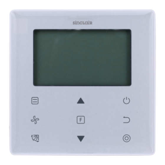
Page 14: Parts Of The Wired Controller
Caution ● Do not play with the wired controller. Accidental operation by a child may result in impairment of bodily functions and harm health. ● Never disassemble the wired controller. Pressing the interior parts may result in electric shocks or fire. Consult your dealer or authorized contractor for internal inspections and adjustments. - Page 15 Table 4.1 Button Functions Mode To set the operating mode: Auto → Cool→ Heat→ Dry→ Fan Fan speed To set the fan speed. Swing To set the swing function. To switch to functions that can be set in the current mode. Function Adjust upwards To adjust temperature setting and timing (for timer) upwards.
-
Page 16: Icons In The Display
3. Icons in the Display ⑤ ① ⑦ ② ⑧ ⑨ ⑩ ③ ④ ⑥ ① Clean filter reminder indicator ② Fan speed ③ Indoor unit ON/OFF ④ Swing ⑤ Operating mode ⑥ Function Lock indicator Signal transmission indicator ⑦ ⑧... - Page 17 Figure 6.1 1) Press (ON/OFF) button, and the Operating Indicator " " on the wired controller will light up, while the ON/OFF icon " " of the indoor unit on the display will spin to indicate that the indoor unit has started running. (see Figure 6.1) 2) Press (ON/OFF) button again, and the Operating Indicator "...
- Page 18 Auto →Cool→Heat→Dry→Fan Figure 6.3 In the "Auto", "Cool", "Dry", or "Heat" mode, press ▲ and ▼ buttons to adjust to the setting temperature. (see Figure 6.4) Figure 6.4 Note: • Temperature setting is not available in the "Fan" mode. 4-3 Fan Speed Setting Figure 6.5...
- Page 19 In the "Cool", "Heat" or "Fan" mode, press (Fan speed) button to set the operating fan speed (see Figure 6.5). If the wired controller is configured with seven fan speeds, press (Fan speed) button to set the fan speed in turn as shown in Figure 6.6. →...
- Page 20 Figure 6.8 (Swing) button is used to turn ON/OFF the swing function (see Figure 6.8). The Swing icon " " will disappear after displayed for 15 seconds, no matter the swing function is turned ON or OFF. Note: • The swing function is only available for indoor units configured with vertical louver.
- Page 21 Press (Function) button to switch to the function that can be set in the current mode (see Figure 6.9). • Press (Function) button to go to the function setting, and the display on the wired controller will show in turns: " ", "...
- Page 22 4-5-2 Silent The "Silent" function is used to send the "Silent" control signal to the indoor unit. The indoor unit automatically optimizes the noise it generates when it is in the "Silent" state. • Turn ON/OFF the "Silent" function: press (Function) button to switch to the "Silent"...
- Page 23 • Turn ON/OFF the "ECO" function: press (Function) button to switch to the "ECO" function (" " blinks), and press (Confirm) button to turn on the function or (Cancel) button to turn off the function (see Figure 6.13). Start Blink Figure 6.13 Note: •...
- Page 24 The "Follow Me" function of the wired controller is on by default, and its icon lights up when the function is on. 1) Turn off "Follow Me": Press (Swing) and (Confirm) buttons at the same time, and hold for 5 seconds to turn off the "Follow Me" function, and its icon disappear. 2) Turn on "Follow Me": When the "Follow Me"...
- Page 25 Figure 6.15 2) "Timer Off" setting: Once the "Timer On" setting is completed, press (Function) button to go to the "Timer Off" setting, the display will show "0.0h Time Off", and the words "Time Of" will blink. press (Confirm) button to go to the timer setting, and press ▲ and ▼...
-
Page 26: Field Setting
4-6 Clean Filer Reminder Figure 6.16 • When the operating time reaches the preset time, the Filter icon " " lights up to remind users to clean the filter. • Press and hold (Swing) button for 5 seconds to remove the Filter icon " ". -
Page 27: Query And Set The Indoor Unit Address
Figure 7.1 2. Query and Set the Indoor Unit Address • If the indoor unit has no address, the indoor unit display will show "FE". • Press and hold ▲ and ▼ buttons for 8 seconds to go to the page to set the indoor unit address. -
Page 28: Commissioning Parameter Settings
required value (address range is 0-63). press (Confirm) button to send the current address value to the indoor unit. In 60 seconds, the wired controller will exit the address setting page, or press (Cancel) button to exit the address setting page. •... - Page 29 Table 5.1 Parameter Parameter Select Default Remarks Code Content Parameters Value Reserved Cooling 00: Cooling and Only/Cooling Heating Heating mode is not available in cooling only and Heating setting. 01: Cooling Setting Only Reserved 00: No reminder to clean filter Set time to 01: 1250h remind users...
- Page 30 Parameter Parameter Select Default Remarks Code Content Parameters Value Select "On" and the operating indicator will show the Settings to 00: Off ON/OFF state of the indoor unit. turn ON/OFF Select "Off" and the operating indicator will always operating 01: On be off regardless the indoor unit is off.
-
Page 31: Troubleshooting
Troubleshooting Table 6.1 Error code and Possible Causes Possible Solutions description IDU is not powered on Power on the IDU. First power off the IDU, and then check if Wired controller connection error the wired controller connection is correct. No display on the See Section 3.4 on the wiring requirements. - Page 32 SINCLAIR CORPORATION Ltd. 1-4 Argyll St. London W1F 7LD Great Britain www.sinclair-world.com This product was manufactured in China (Made in China). REPRESENTATIVE SINCLAIR Global Group s.r.o. Purkynova 45 612 00 Brno Czech Republic TECHNICAL SUPPORT SINCLAIR Global Group s.r.o. Purkynova 45...
Need help?
Do you have a question about the SWC-86E and is the answer not in the manual?
Questions and answers