Table of Contents
Advertisement
Quick Links
Advertisement
Table of Contents

Related Manuals for Sinclair SWC-03


Summary of Contents for Sinclair SWC-03
- Page 1 USER'S MANUAL WIRED CONTOLLER SWC-03...
- Page 2 “Original instructions” IMPORTANT NOTE: Read this manual ca r efully befo r e installing or operating your new air conditioning unit. Make sure to save this manual for future reference.
- Page 3 User Notices For correct installation and operation, please read all instructions carefully. Before reading the instructions, please be aware of the following items: Prohibit installing the wired controller at wet or sunshine places. Do not knock, throw or frequently disassemble the wired controller. ...
-
Page 4: Table Of Contents
Contents 1 DISPLAY ..................... 1 1.1A ..................1 PPEARANCE 1.2 I ......... 2 NSTRUCTIONS FOR ELATED ISPLAYED YMBOLS 2 BUTTONS ....................4 2.1 B ................. 4 UTTON RAPHICS 2.2 F ........... 5 UNCTION NSTRUCTIONS OF UTTONS 3 OPERATION INSTRUCTIONS ..............6 3.1 M ................. - Page 5 4.2 I .............. 43 NSTALLATION EQUIREMENTS 4.3 I ............... 44 NSTALLATION ETHODS 4.4 D ..................46 ISASSEMBLY...
-
Page 6: Display
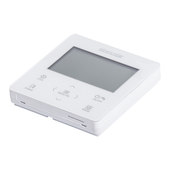
1 Display 1.1 Appearance Fig.1 Appearance of wired controller... -
Page 7: Instructions For Related Displayed Symbols
1.2 Instructions for Related Displayed Symbols Symbols Instructions Up and down swing function Left and right swing function Fresh air function Sleep function Auto mode Cooling mode Dry mode Fan mode Heating mode Health function I-Demand function Absence function Shielding status (Buttons, temperature, ON/OFF, mode or energy saving is shielded by remote monitor) - Page 8 Symbols Instructions Current set fan speed Memory function (Memory in power failure) Save function X-fan function Remind to clean the filter Timer on status Gate card pulled-off status or nobody presented status Quiet function Function lock...
-
Page 9: Buttons
2 Buttons 2.1 Button Graphics Fig. 2 Button graphics... -
Page 10: Function Instructions Of Buttons
2.2 Function Instructions of Buttons Button name Button Function Set low speed, low-medium speed, medium speed, medium-high speed, high speed, turbo and auto speed. (1) Set temperature ∧ (2) Set parameter ∨ (3) Move option cursor (1) Turn on or turn off unit ON/OFF/BACK (2) Return to last page SWING... -
Page 11: Operation Instructions
Button name Button Function (1) Enter menu page MENU/OK (2) Confirm setting Set auto, cooling, dry, fan and heating modes for indoor MODE unit. 3 Operation Instructions 3.1 Menu Structure Normal setting of wired controller can be set directly on the main page, including fan speed, swing, set temperature, mode, ON/OFF. - Page 12 Main menu Once Daily Air function setting Weekly timer Sleep function setting Timer setting menu Two week timer Health function setting Countdown timer on I-DEMAND function setting Countdown timer off Absence function setting Clean function setting Time format setting Clock setting menu Fixed-angle swing function setting Clock setting User function menu...
-
Page 13: On/Off
3.2 On/Off When the wired control is on main page, press ON/OFF button to turn on the unit. Press ON/OFF button again to turn off the unit. The interfaces of On/Off status are shown in Fig. 4 and Fig. 5. Fig. -
Page 14: Temperature Setting
Note: If save function is on, auto mode is not available. 3.4 Temperature Setting Under unit on status, pressing “∧” or “∨” button on the main page increases or decreases set temperature by 1℃(1℉); holding “∧” or “∨” button increases or decreases set temperature by 1℃(1℉) every 0.3s. In cooling, dry, fan and heating mode, temperature setting range is 16℃~30℃(61℉~86℉). -
Page 15: Swing Setting
3.6 Swing Setting In unit on status, press SWING button for swing setting. Two swing modes are available: fixed-angle swing and simple swing. When fixed-angle swing mode is set, swing operation is as follows: In unit on status, press SWING button to select up&down swing Up&down swing angle will be adjusted circularly as below: →... - Page 16 Simple swing mode: when fixed-angle swing mode is turned off, swing operation is as below: Pressing SWING button under unit on status, up&down swing frame occurs. Then press SWING button to turn on or turn off up&down swing. is displayed when up&down swing is on and is not displayed when up&down swing is off.
-
Page 18: Functions Setting
Fig. 7 Swing setting 3.7 Functions Setting Press MENU/OK button on main page to enter main menu page. Press “∧” or “∨” or “<” or “>” button to select the function setting symbol. Then press MENU/OK button to enter user function setting page. Press “∧”... - Page 19 Fig. 8 Function setting...
- Page 20 3.7.1 Fresh Air Function Setting After entering user function page, press “∧” or “∨” button to select fresh air function and press “<” or “>” button to turn on or turn off air function. Press MENU button to adjust the mode of fresh air. After entering fresh air mode setting, press “∧”...
- Page 21 6――The unit continuously runs for 60min, and fresh air valve runs for 36 min. 7――The unit continuously runs for 60min, and fresh air valve runs for 42 min. 8――The unit continuously runs for 60min, and fresh air valve runs for 48 min. 9――The unit continuously runs for 60min, and fresh air valve runs for 54 min.
- Page 22 ② Sleep function will be cancelled when turning off the unit or switching modes. 3.7.3 Health Function Setting After entering user function page, press “∧” or “∨” button to select health function and press “<” or “>” button to turn on or turn off health function with auto saving.
- Page 23 3.7.5 Absence Function Setting After entering user function page, press “∧” or “∨” button to select holiday function option and press “<” or “>” button to turn on or turn off this function with auto saving. This function is used to maintain indoor temperature so that unit can realize fast heating.
- Page 24 3.7.7 Save Function Setting After entering user function page, press “∧” or “∨” button to select save function and press “<” or “>” button to turn on or turn off save function. Press MENU button to enter save function setting page. After entering save function setting page, press “<”...
- Page 25 3.7.9 X-fan Function Setting After entering user function page, press “∧” or “∨” button to select dry function option and press “<” or “>” button to turn on or turn off this function with auto saving. Note: ① This function is only available in cooling mode and dry mode; ②...
- Page 26 3.7.11 Filter Clean Reminder Setting After entering user function page, press “∧” or “∨” button to select clean function option and press “<” or “>” button to turn on or turn off this function. Press MENU button to enter the setting page of filter clean reminder function.
- Page 27 decrease. This function is used to remind you to clean the filter when the unit’s own operating time is reach your setting. Whenever you turn off this function, the unit’s operating time will be zero clearing. 3.7.12 Fahrenheit Temperature Setting After entering user function page, press “∧”...
-
Page 28: Unit Status View
3.7.14 Low-temperature Drying Function Setting After entering user function page, press “∧” or “∨” button to select low-temperature drying function and press “<” or “>” button to turn on or turn off this function with auto saving. Note: ① This function is only available in dry mode; ②... - Page 29 Fig. 9 Status View...
-
Page 30: Current Error View
3.9 Current Error View When error occurs in the unit, error symbol will be displayed on the main page of wired controller to indicate that the unit is with error. In this case, you can enter error view page to view the current error. Press MENU button to enter the menu and select the function symbol to be viewed. - Page 31 Fig. 10 Current Error View...
-
Page 32: Timer Setting
3.10 Timer Setting The wired controller can set 6 kinds of timer: one time clock timer, everyday timer, one week timer, two week timer, countdown timer on and countdown timer off. Select timer symbol after entering menu page. Press MENU button to enter timer setting page. Press “∧” or “∨” button to select one kind of timer. - Page 33 3.10.1 One Time Clock Timer The wired controller can set one time clock timer. If the unit is off, timer on can be set. If the unit is on, timer off can be set. This timer will be carried out for only once when timer time is reached and then the timer will be off automatically.
- Page 34 Fig. 12 Setting page of one time clock timer Note: ① If this timer function is turned on, when the unit is turned on or turned off, this timer function will be cancelled automatically. 3.10.2 Daily Timer In daily timer, user can set eight segments of timer individually. The individual segment will be valid only when it is turned on.
- Page 35 (it is valid only when the current mode is heating). Please refer to Fig. 13. After entering daily timer setting page, press “ < ” or “ > ” button to select setting item. Press “∧” or “∨” button to adjust the value. Press MENU button to save setting.
- Page 36 3.10.3 Weekly Timer The user can set the everyday timer content for a week. In each day, the user can set eight segments of timer content. The unit will execute corresponding timer setting in a week. After entering weekly timer setting page, press “<” or “>” button to select the day to be set.
- Page 38 Fig. 14 Weekly timer setting 3.10.4 Two Week Timer The user can set the everyday timer content for two weeks. In each day, the user can set eight segments of timer content. The unit will execute corresponding timer setting in two weeks. In timer function setting page, press “∧”...
- Page 39 then press “<” or “>” button to set current week as first week or second week. Press MENU button to save current week setting. Please refer to Fig. 15. Fig. 15 Setting of current week After entering two week timer menu page, press “∧” or “∨” button to select the two week schedule option and then press MENU button to enter two week timer programming.
- Page 40 content. Press MENU button to save setting. Press BACK button to exit this page. The setting symbols please refer to weekly timer setting. 3.10.5 Countdown Timer Countdown timer includes timer on and timer off. Unit On/Off after a desired hour can be set. In unit on status, timer off can be set, or timer off and timer on can be set simultaneously.
- Page 41 Fig. 16 Countdown timer on After entering timer off setting page, press “∧” or “∨” button to increases or decreases timer time by 0.5h. Press BACK button to return to the last page. Please refer to Fig. 17.
- Page 42 Fig. 17 Countdown timer off If timer function is on, the set hours will decrease as the unit operation time increases. In this case, residual hours can be viewed after entering timer setting page. This timer function will be carried out for only once and then it will be cancelled automatically.
-
Page 43: Clock Setting
3.11 Clock Setting 3.11.1 Time Format Setting The user can set the time format in 12-hour system or 24-hour system. Select clock symbol in menu page and then press MENU button to enter clock setting page. Press “∧” or “∨” button to select time format and then press “<”... - Page 44 3.11.2 Clock Setting Select clock symbol in menu page and then press MENU button to enter clock setting page. Press “∧” or “∨” button to select time set and then press MENU button to enter time setting. Press “<” or “>” button to select setting items: hour, minute, year, month, day;...
- Page 45 Fig. 19 Clock setting...
-
Page 46: Lock Setting
3.12 Lock Setting Select lock symbol in menu page and then press MENU button to enter lock setting page. Press “∧” or “∨” button to select the item to be locked and then press “<” or “>” button to lock or unlock. Please refer to Fig. -
Page 47: Installation Instructions
Fig. 20 Lock setting 4 Installation Instructions 4.1 Parts and Dimension of Wired Controller Fig. 21 Dimension of wired controller... - Page 48 Fig. 22 Parts of wired controller Name Panel of wired Screw M4X25 Soleplate of wired controller controller Quantity 4.2 Installation Requirements (1) Prohibit installing the wired controller at wet places; (2) Prohibit installing the wired controller at the places with direct sunshine;...
- Page 49 4.3 Installation Methods Fig. 23 Installation diagram for wired controller Fig. 23 is the simple installation process of wired controller; please pay attention to the following items: (1) Before installation, please cut off the power for indoor unit; (2) Pull out the 2-core twisted pair wire from the installation hole on...
- Page 50 wall, and pull this wire through the “ ” hole at the rear side of the soleplate of wired controller; (3) Stick the soleplate of wired controller on the wall and then use screw M4×25 to fix soleplate and installation hole on wall together;...
- Page 51 4.4 Disassembly Fig. 24 Disassembly diagram for wired controller...
- Page 52 SINCLAIR CORPORATION Ltd. 1-4 Argyll St. London W1F 7LD Great Britain www.sinclair-world.com This product was manufactured in China (Made in China). REPRESENTATIVE SINCLAIR EUROPE spol. s r.o. Purkynova 45 612 00 Brno Czech Republic TECHNICAL SUPPORT SINCLAIR Global Group s.r.o. Purkynova 45...
Need help?
Do you have a question about the SWC-03 and is the answer not in the manual?
Questions and answers