Table of Contents
Advertisement
Quick Links
Advertisement
Table of Contents

Related Manuals for Sinclair SWC-02


Summary of Contents for Sinclair SWC-02
- Page 2 User Notices For correct installation and operation, please read all instructions carefully. Before reading the instructions, please be aware of the following items: (1) Prohibit installing the wired controller at wet or sunshine places. (2) Do not knock, throw or frequently disassemble the wired controller. (3) Do not operate the wired controller with wet hands.
-
Page 3: Table Of Contents
Contents 1 Display ..................1 1.1 Appearance ................1 1.2 Instructions for Related Displayed Symbols ....... 2 2 Buttons ..................3 2.1 Button Graphics ................. 3 2.2 Function Instructions of Buttons ..........3 3 Operation Instructions .............. 3 3.1 Menu Structure................3 3.2 On/Off .................. -
Page 4: Display
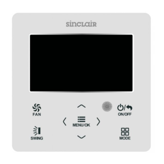
1 Display 1.1 Appearance Fig.1 Appearance of wired controller... -
Page 5: Instructions For Related Displayed Symbols
1.2 Instructions for Related Displayed Symbols Symbols Instructions Up and down swing function Left and right swing function This device does not have Fresh air function. Sleep function Auto mode Cooling mode Dry mode Fan mode Heating mode Health function I-FEEL function This device does not have Absence function. -
Page 6: Buttons
2 Buttons 2.1 Button Graphics Fig. 2 Button graphics 2.2 Function Instructions of Buttons Button name Button Function Set low speed, medium speed,high speed, turbo and auto speed. (1) Set temperature ∧ (2) Set parameter ∨ (3) Move option cursor (1) Turn on or turn off unit ON/OFF/BACK (2) Return to last page... - Page 7 Main menu User function menu Fresh air function setting is not Sleep function setting Health function setting I-FEEL function setting Absence function setting Memory function setting Fixed-angle swing function setting Save function setting Auxiliary heat function setting Dry function setting Quiet function setting is not Air function setting...
-
Page 8: On/Off
3.2 On/Off When the wired control is on main page, press ON/OFF button to turn on the unit. Press ON/OFF button again to turn off the unit. The interfaces of On/Off status are shown in Fig. 4 and Fig. 5. Fig. -
Page 9: Swing Setting
3.6 Swing Setting In unit on status, press SWING button for swing setting. Two swing modes are available: fixed-angle swing and simple swing. When fixed-angle swing mode is set, swing operation is as follows: In unit on status, press SWING button to select up&down swing . - Page 10 Fig. 7 Swing setting...
-
Page 11: Functions Setting
3.7 Functions Setting Press MENU/OK button on main page to enter main menu page. Press “∧” or “∨” or “<” or “>” button to select the function setting symbol. Then press MENU/OK button to enter user function setting page. Press “∧” or “∨” button to select specific function item. - Page 12 3.7.1 Sleep Function Setting After entering user function page, press “∧ ” or “∨ ” button to select sleep function and press “<” or “ >” button to turn on or turn off sleep function with auto saving. If this function is turned on, the unit will operate according to the preset sleep curve to provide comfortable sleep environment.
- Page 13 3.7.6 Save Function Setting After entering user function page, press “ ” or “ ” button to select save function ∧ ∨ and press “ ” or “ ” button to turn on or turn off save function. Press MENU button to <...
- Page 14 3.7.10 Air Function Setting After entering user function page, press “ ” or “ ” button to select Air Function ∧ ∨ and press “ ” or “ ” button to turn on or turn off air function. Press MENU button to <...
-
Page 15: Unit Status View
3.8 Unit Status View Press MENU button to enter the menu and select the function symbol to be viewed. Then press MENU button to enter view function page. Press “∧ ” or “ ∨ ” button to select status view function. Press MENU button to enter unit status view page. Press BACK button to return to the last page. -
Page 16: Current Error View
3.9 Current Error View When error occurs in the unit, error symbol will be displayed on the main page of wired controller to indicate that the unit is with error. In this case, you can enter error view page to view the current error. Press MENU button to enter the menu and select the function symbol to be viewed. - Page 17 Error Error Error Error Code Code Return air temperature sensor open/ Drive board communication error short circuited evaporator temperature sensor open/ Compressor overheating protection short circuited Indoor unit liquid valve temperature Indoor and outdoor units unmatched sensor open/short circuited Indoor gas valve temperature sensor Communication line misconnected or open/ short circuited expansion valve error...
-
Page 18: Timer Setting
3.10 Timer Setting The wired controller can set 6 kinds of timer: one time clock timer, everyday timer, one week timer, two week timer, countdown timer on and countdown timer off. Select timer symbol after entering menu page. Press MENU button to enter timer setting page. Press “∧”... - Page 19 Fig. 12 Setting page of one time clock timer Note: If this timer function is turned on, when the unit is turned on or turned off, this timer function will be cancelled automatically. 3.10.2 Daily Timer In daily timer, user can set eight segments of timer individually. The individual segment will be valid only when it is turned on.
- Page 20 After entering weekly timer setting page, press “<” or “>” button to select the day to be set. Then press MENU button to enter timer programming of that day. Press “<” or “>” button to select the item to be set. Press “∧” or “∨” button to adjust the content. Press MENU button to save setting.
- Page 21 3.10.4 Two Week Timer The user can set the everyday timer content for two weeks. In each day, the user can set eight segments of timer content. The unit will execute corresponding timer setting in two weeks. In timer function setting page, press “∧” or “∨” button to select two week timer setting and then press MENU button to enter two week timer menu page.
- Page 22 After entering timer on setting page, press “ ∧ ” or “ ∨” button to increases or decreases timer time by 0.5h. Press MENU button to save setting. Press BACK button to return to the last page. Please refer to Fig. 16. Fig.
-
Page 23: Clock Setting
This timer function will be carried out for only once and then it will be cancelled automatically. Note: If this timer function is turned on, when the unit is turned on or turned off, this timer function will be cancelled automatically. 3.11 Clock Setting 3.11.1 Time Format Setting The user can set the time format in 12-hour system or 24-hour system. -
Page 24: Lock Setting
Fig. 19 Clock setting 3.12 Lock Setting Select lock symbol in menu page and then press MENU button to enter lock setting page. Press “∧” or “∨” button to select the item to be locked and then press “<” or “>” button to lock or unlock. -
Page 25: Installation Instructions
Fig. 20 Lock setting 4 Installation Instructions 4.1 Parts and Dimension of Wired Controller unit:mm Fig. 21 Dimension of wired controller Fig. 22 Parts of wired controller Panel of wired Soleplate of wired Name Screw M4×25 controller controller Quantity... -
Page 26: Installation Requirements
4.2 Installation Requirements (1) Prohibit installing the wired controller at wet places. (2) Prohibit installing the wired controller at the places with direct sunshine. (3) Prohibit installing the wired controller at the place near high temperature objects or water-splashing places. 4.3 Installation Methods Connect to either H1 terminal or H2 terminal. -
Page 27: Disassembly
(3) Stick the soleplate of wired controller on the wall and then use screw M4×25 to fix soleplate and installation hole on wall together; (4) Insert the four-core twisted pair line into the slot of the wired controller and then buckle the front panel and the soleplate of the wired controller together.
Need help?
Do you have a question about the SWC-02 and is the answer not in the manual?
Questions and answers