Table of Contents
Advertisement
Quick Links
Advertisement
Table of Contents

Related Manuals for Sinclair SWC-04


Summary of Contents for Sinclair SWC-04
- Page 1 User Manual | - - Ver. 19 07 2021 WIRED CONTROLLER SWC-04...
- Page 2 „ O R I G I N A L I N S T R U C T I O N S “ I M P O R T A N T N O T E : Read this manual carefully before installing or operating your new air conditioning unit. Make sure to save this manual for future reference.
- Page 3 For downloading manual for this pro- Pro stažení manuálu k tomuto pro- duct, please enter the model name at duktu zadejte modelové označení do this link: následujícího odkazu: Pre stiahnutie manuálu k tomuto pro- Um das Handbuch für dieses Produkt duktu zadajte modelové...
- Page 4 User Notice Never install the wired controller in the moist circumstance or expose it directly under the ◆ sunlight. ◆ Never beat, throw, and frequently disassemble the wired controller and the wireless remote controller. ◆ Never operate the wired controller and the wireless remote controller with wet hands. Do not remove or install the wired controller by yourself.
-
Page 5: Table Of Contents
Contents Wired Controller SWC-04................1 1 Symbols on LCD ................... 1 1.1 Outside View of the Wired Controller ..............1 1.2 LCD of the Wired Controller ................. 1 2 Buttons ......................2 2.1 Buttons on the Wired Controller ................2 2.2 Function of the Buttons ..................3 3 Operation Instructions ................... -
Page 6: Symbols On Lcd
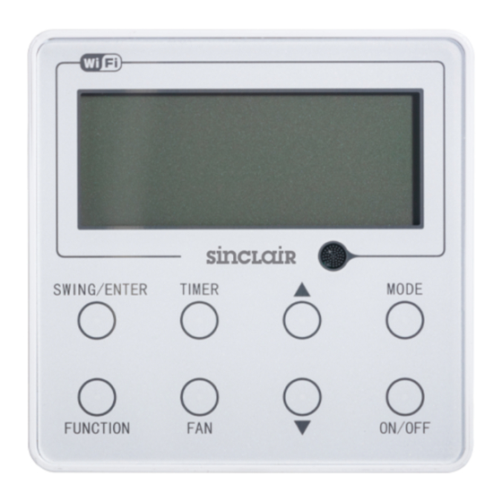
Wired Controller SWC-04 Wired Controller SWC-04 1 Symbols on LCD 1.1 Outside View of the Wired Controller Fig.1 Outside View of the Wired Controller 1.2 LCD of the Wired Controller Fig.2 LCD of the Wired Controller... -
Page 7: Buttons
Wired Controller SWC-04 Table 1 Display Instruction of Display Automatic mode (under auto mode, the indoor unit will select its Auto operating mode according to the variation of room temperature) Cool Cooling mode Dry mode Fan mode Heat Heating mode... -
Page 8: Function Of The Buttons
Wired Controller SWC-04 2.2 Function of the Buttons Table 2 Name Function Function selection and cancellation. ① SWING/ENTER Setting of the up and down swing function. ② ▲ Running temperature setting of the indoor unit, range:16~30°C(61~86°F). ① Timer setting, range:0.5-24 hr. -
Page 9: Operation Instructions
Wired Controller SWC-04 3 Operation Instructions 3.1 ON/OFF Press ON/OFF to turn on the unit and turn it off by another press. Note: The state shown in Fig.4 indicates the “OFF” state of the unit after power on. The state shown in Fig.5 indicates the “ON”... -
Page 10: Fan Setting
Wired Controller SWC-04 Fig.6 3.4 Fan Setting Under the “ON” State of the unit, press Fan and then fan speed of the indoor unit will change circularly as shown in Fig.7. Auto (Low) (Medium low) (Medium) (Medium high) (High) Fig.7 3.5 Timer Setting... -
Page 11: Up & Down Swing Setting
Wired Controller SWC-04 Press “TIMER” button to set Press ▲ or ▼ button to adjust time Press “TIMER” button to cancel Press “SWING/ENTER” to finish timer setting timer setting Fig. 8 Timer off Setting under the “ON” State of the Unit Timer range: 0.5-24hr. -
Page 12: Left & Right Swing Setting
Wired Controller SWC-04 3.7 Left & Right Swing Setting Swing On: Press FUNCTION under on state of the unit to activate the swing function. In this case, will blink. After that, press SWING/ENTER to make a confirmation. Swing Off: When the Swing function is on, press FUNCTION to enter the Swing setting interface, with blinking. -
Page 13: Fresh Air Function Setting
Wired Controller SWC-04 3.8 Fresh Air Function Setting Valve Turn on fresh air valve function: Under unit on status, press FUNCTION button on the panel to select “Fresh air valve” function option. When icon flashes, it enters fresh air valve setting mode. Previous temperature display position will display the level of fresh air valve. -
Page 14: Sleep Setting
Wired Controller SWC-04 3.9 Sleep Setting Sleep on: Press FUNCTION under on state of the unit till the unit enters the Sleep setting interface. Press SWING/ENTER to confirm the setting. Sleep off: When the Sleep function is activated, press FUNCTION to enter the Sleep setting interface. -
Page 15: Turbo Setting
Wired Controller SWC-04 3.10 Turbo Setting Turbo function: The unit at the high fan speed can realize quick cooling or heating so that the room temperature can quickly approach the setting value. In the Cooling or Heating mode, press FUNCTION till the unit enters the Turbo setting interface... -
Page 16: Energy Saving Function Setting
Wired Controller SWC-04 3.11 Energy Saving Function Setting Turn on energy saving function: 1)Energy Saving Setting for Cooling When the unit runs under the COOL or DRY mode, press FUNCTION button to select "SAVE" function option, with "SAVE" flashing, and then press ▲ or ▼ to adjust the lower limit, after that, press the SWING/ENTER button to activate this function. -
Page 17: E-Heater Setting
Wired Controller SWC-04 3.12 E-heater Setting E-heater (auxiliary electric heating function): In the Heating mode, E-heater is allowed to be will be Once the wired controller or the remote controller enters the Heating mode, this function turned on automatically. Press FUNCTION in the Heating mode to enter the E-heater setting interface and then press SWING/ENTER to cancel this function. -
Page 18: X-Fan Setting
Wired Controller SWC-04 3.13 X-fan Setting X-fan function: After the unit is turned off, the water in evaporator of indoor unit will be automatically evaporated to avoid mildew. In the Cooling or Dry mode, press FUNCTION till the unit enters the X-fan setting interface and then press SWING/ENTER to active this function. -
Page 19: Quiet Function Setting
Wired Controller SWC-04 3.14 Quiet Function Setting Turn on quiet function: Under unit on status, press FUNCTION button on the panel to select “Quiet” function option. When “Quiet” or “Auto quiet” flashes, it enters quiet function setting mode. Press ▲ or ▼ button to switch between “Quiet”... -
Page 20: Health Setting
Wired Controller SWC-04 3.15 Health Setting Health on: Press FUNCTION under on state of the unit till the unit enters the Health setting interface. Press SWING/ENTER to confirm the setting. Health off: When the Health function is activated, press FUNCTION to enter the Health setting interface. -
Page 21: Absent Setting
Wired Controller SWC-04 3.16 Absent Setting Absent on: Press FUNCTION under on state of the unit till the unit enters the Absent setting interface. Press SWING/ENTER to confirm the setting. Absent off: When the Absent function is activated, press FUNCTION to enter the Absent setting interface. -
Page 22: I-Demand Setting
Wired Controller SWC-04 3.17 I-Demand Setting I-Demand on: Press FUNCTION under on state of the unit till the unit enters the I-Demand setting interface. Press SWING/ENTER to confirm the setting. I-Demand off: When the I-Demand function is activated, press FUNCTION to enter the I-Demand setting interface. -
Page 23: Wifi Function Setting
Wired Controller SWC-04 3.18 WiFi Function Setting "EWPE Smart" APP can be used to control it. The app can be downloaded via Google Play or App Store. APP can only set some common functions of WiFi wired controller: ON/OFF, mode, set temperature, FAN speed, etc. -
Page 24: Installation And Dismantlement
Wired Controller SWC-04 Select the temperature sensor at the wired controller under the cooling, dry and fan modes, ④ and select the temperature sensor at the return air inlet under the heating mode and auto modes (04 displayed in the timer display area). - Page 25 Fig. 21 Note: CN1 is 485 communication interface and it used Wired Controller SWC-04 for connecting the 4-core communication wire. These two needle stands(CN2、CN3) are used for connecting the smart zone controller. There is no sequence for these two needle stands. You can connect one or two needle stand(s) basing on the requirement.
- Page 26 Wired Controller SWC-04 For matching with different models, the patch cord and the connection wire are provided in the packaging box of wired controller. As shown in fig. 22. Fig. 22: Schematic diagram of patch cord and connection wire ● If the air conditioner has been installed with the patch cord (fig. 24) used for connecting the wired controller.
- Page 27 DIP switch. There is a 2-bit DIP switch on the main board of wired controller SWC-04. As for the last #n wired controller in the control system, the 1-bit and the 2-bit of the DIP switch should be manually pulled to position “on” and position “off” respectively. The DIP switches of other wired controllers should be kept at the initial ex-factory status (1-bit and 2-bit are set at position “off”).
-
Page 28: Dismantlement Of The Wired Controller
Wired Controller SWC-04 cord and connection lines between the indoor and outdoor unit, with a minimum interval of 20cm, otherwise the communication of the unit will probably work abnormally. If the air conditioning unit is installed where is vulnerable to electromagnetic interference, ②... - Page 29 Wired Controller SWC-04 Table 4 Meaning of Each Error Error Error Error Error Code Code Return air temperature sensor open/short Drive board communication error circuited evaporator temperature sensor open/short Compressor overheating protection circuited Indoor unit liquid valve temperature sensor Indoor and outdoor units unmatched...
- Page 30 Wired Controller SWC-04 Table 4 Meaning of Each Error Error Error Error Error Code Code Communication error between IDU and IDU network address error grid connection Communication error between ODU and Ip address allocation overflow grid connection Main error at grid connection side...
- Page 31 Great Britain www.sinclair-world.com This product was manufactured in China (Made in China). R E P R E S E N T A T I V E SINCLAIR Global Group s.r.o. Purkynova 45 612 00 Brno Czech Republic T E C H N I C A L S U P P O R T SINCLAIR Global Group s.r.o.
- Page 32 N O T E S...
- Page 33 N O T E S...
- Page 34 N O T E S...
- Page 35 For downloading manual for this pro- Pro stažení manuálu k tomuto pro- duct, please enter the model name at duktu zadejte modelové označení do this link: následujícího odkazu: Pre stiahnutie manuálu k tomuto pro- Um das Handbuch für dieses Produkt duktu zadajte modelové...
- Page 36 66139901148...
Need help?
Do you have a question about the SWC-04 and is the answer not in the manual?
Questions and answers