Table of Contents
Advertisement
Quick Links
Advertisement
Table of Contents

Related Manuals for Sinclair SWC-05W


Summary of Contents for Sinclair SWC-05W
- Page 1 User Manual 26 05 2023 Ver. WIRED CONTROLLER SWC-05W...
- Page 2 „ O R I G I N A L I N S T R U C T I O N S “ I M P O R T A N T N O T E : Read this manual carefully before installing or operating your new air conditioning unit. Make sure to save this manual for future reference.
- Page 3 To Users Thank you for selecting Sinclair product. Please read this instruction manual carefully before installing and using the product, so as to master and correctly use the product. In order to guide you to correctly install and use our product and achieve...
- Page 4 it may cause relative damage, and our company will bear no responsibilities. This marking indicates that this product should not be disposed with other household wastes throughout the EU. To prevent possible harm to the environment or human health from uncontrolled waste disposal, recycle it responsibly to promote sustainable reuse...
-
Page 5: Table Of Contents
Contents 1 Safety Notices (Please be sure to abide them) ..1 2 Operation Notices............1 3 Display ................ 3 3.1 LCD of Wired Controller ..........4 3.2 LCD Display Instruction ..........4 4 Installation and Commissioning ......7 4.1 Instruction of Wired Controller ........8 4.2 Commissioning ............ - Page 6 5.9 Air Setting* ..............40 5.10 Save Setting .............. 41 5.11 Filter Clean Reminder Setting ........43 5.12 X-FAN Setting ............45 5.13 Health Setting* ............46 5.14 I-DEMAND Setting* ........... 46 5.15 Absence Setting ............47 5.16 Remote Shield Function ..........47 5.17 Child Lock Function ...........
-
Page 7: Safety Notices (Please Be Sure To Abide Them)
Owner’s Manual 1 Safety Notices (Please be sure to abide them) WARNING: If not abide them strictly, it may cause severe damage to the unit or the people. NOTE: If not abide them strictly, it may cause slight or medium damage to the unit or the people. - Page 8 Owner’s Manual When two wired controllers control one (or more) indoor unit(s), the address of wired controller should be different. Functions with “*” are optional for indoor units. If a function is not included in an indoor unit, wired controller can’t set the function, or setting of this function is invalid to the indoor unit.
-
Page 9: Display
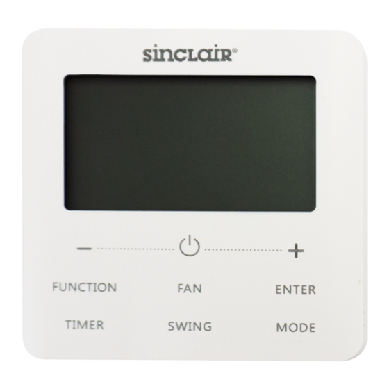
Owner’s Manual 3 Display Fig. 3.1 Appearance of wired controller... -
Page 10: Lcd Of Wired Controller
Owner’s Manual 3.1 LCD of Wired Controller Fig. 3.2 LCD graphics of wired controller 3.2 LCD Display Instruction Table 3.1 LCD display instruction Symbols Instructions Gate-control function. Child Lock status. Slave wired controller (address of wired controller is 02). One wired controller controls multiple indoor units. - Page 11 Owner’s Manual Symbols Instructions Outdoor unit defrosting status. Shielding status. Current wired controller connects master indoor unit. Fresh air control function. Indicates that the current system mode priority is voting mode. WiFi status (If the wired controller has no WiFi function, it displays only when the unit connected to “Cloud”).
- Page 12 Owner’s Manual Symbols Instructions Auto clean status. Save status of indoor unit. Air status, Indoor unit optional function. I-DEMAND function, Indoor unit optional function. Quiet status (including Quiet and Auto Quiet two status). Sleep status. Left and right swing function. Up and down swing function.
-
Page 13: Installation And Commissioning
Owner’s Manual Symbols Instructions Cooling mode. It shows the value of temperature, and displays the current type of value (In case the wired controller is controlling a Fresh Air Indoor Unit, then it will display FAP). NOTE: When wired controller is connected with different indoor units, some functions will be different. -
Page 14: Instruction Of Wired Controller
Owner’s Manual Fig. 4.2 Parts and Components of Wired Controller Panel of Self-tapping Soleplate Screw Name wired screw of wired M4×25 controller ST3.9×25 MA controller 4.1 Instruction of Wired Controller 4.1.1 Requirements for Model Selection of Communication Wire Fig. 4.3 Length of communication wire... - Page 15 Owner’s Manual Wire material Total length Wire size Material Remarks type L (m/feet) /AWG) standard (1) Total length of communication line can't exceed 250m Light/ (820-1/5feet). Ordinary (2) The cord shall be Polyvinyl 2×0.75 Circular cord (the chloride L≤250m ~2× IEC 60227- cores shall be twisted sheathed...
- Page 16 Owner’s Manual Fig. 4.4 one wired controller Fig. 4.5 two wired controllers controls one indoor unit control one indoor unit...
- Page 17 Owner’s Manual Fig. 4.8 one wired controller controls multiple UNI split 2 indoor units simultaneously Fig. 4.9 two wired controller control multiple UNI split 2 indoor units simultaneously...
- Page 18 Owner’s Manual Instruction for wire connection: (1) The wiring methods in fig. 4.4, fig. 4.5, fig. 4.8 and fig. 4.9 can be adopted for the wired controller connecting UNI split 2. (2) When one (or two) wired controller(s) control(s) multiple indoor units simultaneously, the wired controller can connect to any one indoor unit, but the connected indoor unit must be the same series indoor unit.
- Page 19 Owner’s Manual NOTE: Wired controller SWC-05W only supports one (or more) indoor unit(s) controlled by a joint command. 4.1.4 Installation Fig. 4.10 Installation of Wired Controller...
- Page 20 Owner’s Manual Fig. 4.10 shows a simple installation course of wired controller, and the following points should be noted: (1) Before installation, please cut off the power supply of indoor unit, it is not allowed to operate with power supply; (2) Pull out the 2-core twisted pair inside the installation hole in the wall, and thread the wire through the hole in the back of soleplate of wired controller;...
-
Page 21: Commissioning
Owner’s Manual 4.2 Commissioning 4.2.1 Set Master Indoor Unit Under Off status, long press “MODE” button for 5s to set the corresponding indoor unit of wired controller as master indoor unit. If the system mode priority is the master-slave mode, “ ”... - Page 22 Owner’s Manual The parameter enquiry list is as following: Table 4.1 Parameters viewing list Parameter Parameter Parameter Viewing method code name range Press “MODE” button in “C01” status. Press “+” or “-” button to select the project number of indoor unit.
- Page 23 Owner’s Manual Parameter Parameter Parameter Viewing method code name range View the indoor unit Timer zone: display quantity of 1-100 indoor unit quantity of the the system system. network* Operation method: Enter viewing: press “MODE” button in “C06” status to enter the interface of viewing priority operation.
- Page 24 Owner’s Manual Parameter Parameter Parameter Viewing method code name range Enter viewing: press “MODE” button in “C07” status. Press “+” or “-” button to select indoor View indoor unit. ambient — Temperature zone: temperature displays current indoor unit project number; Timer zone: displays indoor ambient temperature.
- Page 25 Owner’s Manual Parameter Parameter Parameter Viewing method code name range Timer zone: displays the View the indoor unit quantity indoor unit 1-16 controlled by the wired quantity controller. View Timer zone: displays outdoor — outdoor ambient ambient temperature. temperature Press “MODE” button to enter into the review interface of indoor relative humidity under “C17”...
- Page 26 Owner’s Manual Parameter Parameter Parameter Viewing method code name range Press “MODE” button in “C18” status to turn on the function of one-button viewing indoor unit project code. Press “+” or “-” button to select the indoor unit. Temperature zone: displays number of the 1-255: current indoor unit...
- Page 27 Owner’s Manual Parameter Parameter Parameter Viewing method code name range Cancel method: 1)If user exits the “C18” interface manually, the one-button viewing function will be immediately turned off. 2)If system exits the “C18” interface due to no action in 20 1-255: One-button seconds, user has to...
- Page 28 Owner’s Manual Parameter Parameter Parameter Viewing method code name range Enter viewing, short-press “MODE” button in “C20” status. Press “+” or “-” button to select the indoor View the air unit. outlet Temperature zone: temperature — displays current indoor of Fresh Air unit project number Indoor Unit* Timer zone: displays air...
- Page 29 Owner’s Manual 4.2.3 Parameter Setting Unit parameters can be set in unit On or Off status. (1) Long press “FUNCTION” button for 5s and the temperature zone displays “C00”; long press “FUNCTION” button for another 5s to enter the interface of setting wired controller parameters.
- Page 30 Owner’s Manual Parameter Parameter Default Parameter name Note code range value Set infrared 00: forbidden receiver of — 01: activated wired controller Assistant wired 01: master controller (02) is Set address of wired controller without unit wired controller 02: slave wired parameter setting controller function except...
- Page 31 Owner’s Manual Parameter Parameter Default Parameter name Note code range value 00: general NOTE: not applicable Set Timer* timer to partial units. 01: clock timer Available only when Clock Timer 00: once timer is set to clock repetition is 01: repeat timer.
- Page 32 Owner’s Manual Parameter Parameter Default Parameter name Note code range value When power supply is insufficient, the indoor 00: normal units which are set to Set priority operation priority operation can operation* 01: priority operate, while other operation indoor units are forced to be turned off.
- Page 33 Owner’s Manual Parameter Parameter Default Parameter name Note code range value Air outlet temperature setting for 16°C~30°C 22°C Only applicable to Fresh Air (61°F~86°F) (71°F) Fresh Air Indoor Unit. Indoor Unit in heating* After union function is set, Fresh Air Indoor Unit will be turned 00: without Union setting of...
- Page 34 Owner’s Manual Parameter Parameter Default Parameter name Note code range value lower limit ≥ 4°C; Temperature When temperature lower limit for 16~26°C 20°C unit is °F, Setback (61~79°F) (68°F) temperature upper Function limit – temperature lower limit ≥7°F. When it is set as 00, it will keep the status When inserting after inserting the...
- Page 35 Owner’s Manual Parameter Parameter Default Parameter name Note code range value When it is set as 01 and the timer setting way is clock timer, the 00: 24-hour system time in the Set time format 01: 12-hour homepage will be displayed in 12 hour- clock with the AM/PM indicator.
- Page 36 Owner’s Manual Parameter Parameter Default Parameter name Note code range value NOTE: Only temperature of applicable to the unit 10℃~30℃ 16℃ humidity control with humidity control (50°F~86°F) (61°F) under Dry function under Dry mode mode. NOTE: Only 01: Normal Auto clean applicable to the unit 02: Quick mode...
-
Page 37: Operation Instructions
Owner’s Manual 5 Operation Instructions 5.1 ON/OFF Press “ ” button to turn on the unit. Press “ ” button again to turn off the unit. The interfaces of “ON/OFF” status are shown in fig. 5.1 ~ 5.2. Fig. 5.1 Interface of On status Fig. -
Page 38: Temperature Setting
Owner’s Manual ② Under Auto mode, if the indoor unit is running under Cooling, the icons “ ” and “ ” will light up; if the indoor unit is running under Heating, the icons “ ” and “ ” will light up. 5.3 Temperature Setting Press “+”... -
Page 39: Fan Setting
Owner’s Manual can the setting temperature be adjusted by pressing “+” or “-” under Auto mode. ② When Absence function is activated, the setting temperature cannot be adjusted by pressing “+” or “-”. ③ When the wired controller is connected with a Fresh Air Indoor Unit, fresh air indoor unit code “FAP”... -
Page 40: Timer Setting
Owner’s Manual When Turbo function is activated, Turbo function icon “ ” will be bright. NOTES: ① Under Dry mode, fan speed is low and can’t be adjusted. ② When the wired controller is connected with a Fresh Air Indoor Unit, fan speed of indoor unit will be high fan speed only. - Page 41 Owner’s Manual 5.5.2 Clock Setting Clock display: when the timer setting way is clock timer, timer zone displays system clock in unit On and Off status. The clock can be set at this time. Clock setting: long press “TIMER” button for 5s to enter clock setting.
- Page 42 Owner’s Manual press “ENTER” button to cancel timer. Press “+” or “-” button to increase or decrease timer time by 1min; hold “+” or “-” button for 5s to increase or decrease timer time by 10min; hold “+” or “-” button for 10s to increase or decrease 60min. Clock Timer setting is as shown in fig.
- Page 43 Owner’s Manual Fig. 5.3 Unit On/Off time setting in unit On status...
-
Page 44: Swing Setting
Owner’s Manual NOTE: It is not applicable to partial units. 5.6 Swing Setting In unit on status, up & down swing function and left & right swing function can be set. (1) Up & down swing function Up & down swing function has two modes: simple swing mode and fixed-angle swing mode. -
Page 45: Sleep Setting
Owner’s Manual 3D heating, Space heating mode. Turn on Quiet Function: press “FUNCTION” button to turn to Quiet function and then Quiet icon “ ” or auto quiet icon “ ” is blinking. At this moment, press “+” or “-” button to switch between quiet and auto quiet, and then press “ENTER”... -
Page 46: Air Setting
Owner’s Manual Under Auto, Fan or Floor Heating mode, the Sleep function is not available. 5.9 Air Setting* Air Function: Adjust the amount of indoor fresh air to improve air quality and keep indoor air fresh. Turn on Air Function: When unit is on or off, press “FUNCTION” button and select Air. -
Page 47: Save Setting
Owner’s Manual Level of Air setting Opening time of fresh air Always on valve NOTE: time indicated in the table: unit’s operating time (min) / opening time of fresh air valve per operating time (min). 5.10 Save Setting Save Function: Air conditioner can be operated in small temperature range by setting the minimum temperature under Cooling and Dry modes and setting maximum temperature under Heating, 3D Heating and Space Heating modes. - Page 48 Owner’s Manual Fig. 5.4 shows how to set Save function for Cooling: Fig. 5.4 Save Setting for Cooling...
-
Page 49: Filter Clean Reminder Setting
Owner’s Manual Start up Save function for Heating: When the unit is off, simultaneously press “TIMER” and “+” buttons for 5s, the buzzer will give out a sound and then unit will enter into Save setting mode. “ ” icon is blinking. Mode icon is on. Press “MODE” button to switch to Heating or 3D Heating or Space Heating mode. - Page 50 Owner’s Manual range is 00, 10-39. Press “ENTER” to turn on this function. Turn off Filter Clean Reminder Function: When unit is on and this function has been turned on, press “FUNCTION” button and select Clean. Then “ ” icon will blink. Set the cleaning level as 00 and press “ENTER”...
-
Page 51: X-Fan Setting
Owner’s Manual Cleaning Description of Levels Level Turn off Timer zone shows 00 Clean The former digit shows 1 while the latter one shows 0, which indicates the accumulating operating time is 5500 Slight hours. Each time the latter digit increases 1, the operating Pollution time increases 500 hours. -
Page 52: Health Setting
Owner’s Manual Under Cooling or Dry mode, press “FUNCTION” button to select X-fan. “ ” icon will blink. Then press “ENTER” button to turn on/off this function. 5.13 Health Setting* Health Function: Control the air purification module which can purify air. This function cannot be used under Floor Heating mode. When unit is on, press “FUNCTION”... -
Page 53: Absence Setting
Owner’s Manual d2 and d3. Level "1" indicates the defaulted I-DEMAND function, d2 indicates DRED2 power-decreasing mode and d3 indicates DRED3 power-decreasing mode. Press “ENTER” button to save the setting and turn on I-DEMAND function. Cancel I-DEMAND function: When I-DEMAND function is turned on, press “FUNCTION”... -
Page 54: Child Lock Function
Owner’s Manual Shield on the wired controller, “ ” icon will show. If user wants to control through the wired controller, “ ” icon will blink to remind that these controls are disabled. 5.17 Child Lock Function When unit is turned on normally or turned off, pressing “+” and “-”... -
Page 55: Auto Clean Function
Owner’s Manual Within the 5 seconds, it can quit displaying the indoor temperature immediately and be responded to the instructions as usual after pressing any buttons. 5.20 Auto Clean Function In the homepage, hold “MODE” and “TIMER” buttons for 5 seconds to turn on or turn off Auto Clean function. - Page 56 Owner’s Manual Fig. 5.5 shows how to turn on Auto Clean function: Fig. 5.5 Turn on Auto Clean function NOTES: ① This function is only applicable to the unit with Auto Clean function. ② When the unit is faulty, Auto Clean function cannot be turned on. ③...
-
Page 57: Wifi Function Setting
5.21 WiFi Function Setting "EWPE" App can be used to control wired controller SWC-05W. Please scan the QR code or search "EWPE" in theapplication market to download and install it. When "EWPE" App isinstalled, register the account and add the device to achieve long-distance control and LAN control of EWPE smart home appliances. -
Page 58: Setback Function
Owner’s Manual NOTES: ① This function is only applicable to wired controller SWC-05W. ② If the device is offline or router’s name and password have been changed, please reset WiFi and add the device again. ③ WiFi networking performance is related to the distance between the wired controller and the router and the obstacles between them. -
Page 59: Error Display
Owner’s Manual NOTES: ① Setback Function is forbidden as defaulted; you can activate or forbid Setback Function through P71 parameter setting. ② When the slave indoor unit is operating in Setback Function, it cannot operate in the mode which is in conflict with that of master indoor unit. - Page 60 Owner’s Manual Fig. 6.1 Display of Outdoor Unit High Pressure Protection...
-
Page 61: Table Of Display Codes For Uni Split 2 Unit
Owner’s Manual 6.1 Table of Display Codes for UNI split 2 Unit 6.1.1 Table of Error Codes of Outdoor Unit Error Error Content Content Code Code Discharge Protection Outdoor Fan 2 Error Overload Protection Outdoor Fan 1 Error ODU AC Current System Low Pressure Protection Protection... - Page 62 Owner’s Manual Error Error Content Content Code Code High Voltage Protection of Compressor DC Bus Demagnetization Protection Low Voltage Protection of Compressor Stalling DC Bus Drive Board Communication Startup Failure Error Overcurrent of Compressor Drive Module Reset Phase Current Overspeed DC Input Voltage Error Abnormal Outdoor Ambient Temperature (heating at too...
- Page 63 Owner’s Manual Error Error Content Content Code Code Low Pressure Sensor Refrigerant Temperature Error Sensor Error Outdoor Pipe Middle ODU Refrigerant Heater Sensor Error Failure High Pressure Switch 2 ODU Refrigerant Heater Error Relay Adhesion Error Compressor Drive Storage Communication Error Chip Error between ODU and IDU Outdoor Fan Out-of-phase...
- Page 64 Owner’s Manual Error Error Content Content Code Code Abnormal Electrical Level of Zero-crossing Signal Error Selected Port Outdoor Ambient Memory Chip Read and Temperature Sensor Error Write Error Refrigerant Lacking — — Protection 6.1.2 Table of Error Codes of Indoor Unit Error Error Content...
- Page 65 Owner’s Manual Error Error Content Content Code Code Low Voltage Protection or Inverter Indoor Fan Drive Voltage Drop Error of Electric Box Temperature Inverter Indoor Fan Drive Sensor Error DC Bus High Voltage Protection of Inverter Indoor Fan Drive AC Inverter Indoor Fan Drive Input Zero-crossing DC Bus...
- Page 66 Owner’s Manual Error Error Content Content Code Code Group-controlled IDU — — Quantity Inconsistency 6.1.3 Table of Status Codes Status Status Content Content Code Code Auto clean DRED operation mode 1 Refrigerant recycle mode DRED operation mode 2 Ordinary defrosting status DRED operation mode 3...
- Page 67 Please ask your local council where your nearest disposal station is located. P R O D U C E R R E P R E S E N T A T I V E SINCLAIR CORPORATION Ltd. SINCLAIR Global Group s.r.o. 16 Great Queen Street Purkynova 45 WC2B 5AH London...
Need help?
Do you have a question about the SWC-05W and is the answer not in the manual?
Questions and answers