Table of Contents
Advertisement
Advertisement
Table of Contents

Related Manuals for Sinclair XK117


Summary of Contents for Sinclair XK117
- Page 1 USER'S MANUAL WIRED CONTOLLER XK117...
- Page 2 “Original instructions” IMPORTANT NOTE: Read this manual ca r efully befo r e installing or operating your new air conditioning unit. Make sure to save this manual for future reference.
- Page 3 To Users Thank you for selecting Sinclair’s product. Please read this instruction manual carefully before installing and using the product, so as to master and correctly use the product. In order to guide you to correctly install and use our product and...
-
Page 4: Table Of Contents
Contents 1 Installation ..................1 1.1 Dimension and Component of Wired Controller ........1 1.2 Installing Position and Requirements of Wired Controller ......2 1.3 Installation of Wired Controller ............3 1.4 Disassembly of Wired Controller ............5 2 Introduction to Display ................5 2.1 Outline of Wired Controller ............... - Page 5 3.9.4 Setting of Memory Function ............ 18 3.9.5 Switch between Fahrenheit and Degree Celsius ......18 3.9.6 Inquiry of Ambient Temperature ..........18 4 Display of Errors ................19...
-
Page 6: Installation
1 Installation Dimension and Component of Wired Controller Figure 1-1 Dimension of Wired Controller (Unit:mm) Figure 1-2 Components of Wired Controller... -
Page 7: Installing Position And Requirements Of Wired Controller
Table 1.1.1 Introduction of Components ① ② ③ ④ Name wired screw M4×25 installing box of junction box for in- controller wired controller stalling inside the wall Quantity 1(prepared by user) Installing Position and Requirements of Wired Controller (1) Please do not install the wired controller in the position where is wet or is likely to be splashed with water;... -
Page 8: Installation Of Wired Controller
(6) The wired controller should only be installed indoors, and its working tempera- ture range is 0℃~50℃. Installation of Wired Controller First to select the right signal wire of wired controller: 2–core signal wire (wire di- ameter>=0.75mm, length<30m, recommendable length is 8m). For installation steps of wired controller please refer to the following sketch map, brief instructions are as below: (1) Before installation, please cut off the power supply of indoor unit, live working... - Page 9 (5) Buckle the panel of wired controller with the soleplate, then the installation is finished. Figure 1-3 Sketch Map for Installation of Wired Controller...
-
Page 10: Disassembly Of Wired Controller
Disassembly of Wired Controller Disassembly for wired controller is as below: Figure 1-4 Sketch Map for Disassembly of Wired Controller 2 Introduction to Display Outline of Wired Controller Figure 2-1 Outline of Wired Controller... -
Page 11: Liquid Crystal Display Of Wired Controller
Liquid Crystal Display of Wired Controller Figure 2-2 Liquid Crystal Display of Wired Controller Instruction for Liquid Crystal Display of Wired Controller Table 2.3.1 Instruction for Liquid Crystal Display of Wired Controller Display Instruction of Display Automatic mode (under auto mode, the indoor unit will select its operating mode according to the var- Auto iation of room temperature) - Page 12 Display Instruction of Display Exchange Display when air exchange function is set Display when silent function is set (only display si- Silent lent, no AT) Display when health function is set Health Display when absent function is set Absent Display when I-DEMAND function is set I-DEMAND WIFI function icon (reserve this function, no this WIFI...
-
Page 13: Instruction For Operation
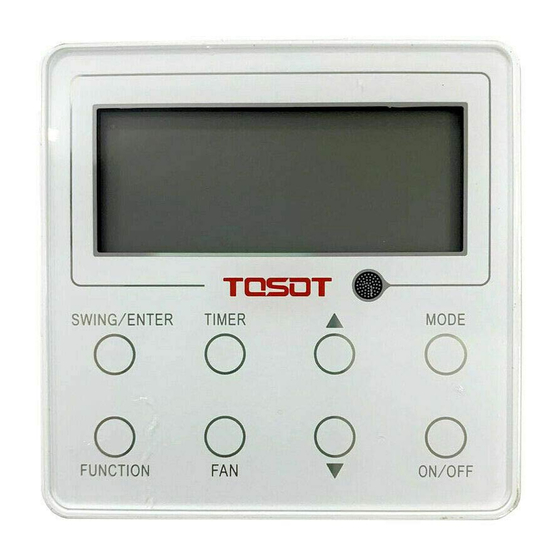
Display Instruction of Display Filter washing reminder Clean Display when energy-saving function is set Save Defrosting status Defrost Display when timer status is set Timer Shielding status Shield 3 Instruction for Operation Silkscreen of Buttons Figure 3-1 Silkscreen of Buttons ON/OFF Setting Press “ON/OFF”... - Page 14 Figure 3-2 ON Status Figure 3-3 OFF Status...
-
Page 15: Mode Setting
Mode Setting Under power-on status, each time press the “MODE” button, the mode will switch circularly according to the following order, as shown in the figure. Figure 3-4 Mode Setting Note: Under auto mode, if the unit conducts auto cooling, then“ ”... - Page 16 Temperature setting range under cooling, dry, fan and heating mode is: 16℃~ 30℃. The setting temperature cannot be adjusted under auto mode. Figure 3-5 Setting of Temperature...
-
Page 17: Setting Of Fan Speed
Setting of Fan Speed Under power-on status, press “FAN” button, the fan speed will switch circularly according to the following order, as shown below. Figure 3-6 Setting of Fan Speed Note: (1) Under dry mode, the fan speed will automatically set as low speed, and the fan speed cannot be adjusted. -
Page 18: Setting Of Timer Function
simultaneously for 5 seconds, the up & down swing icon will flash, then switch for simple swing and fixed swing is done. When it is set to be simple swing, under power-on status, press “SWING/ ENTER” button, the mode is activated, press the button again the mode is turned off. -
Page 19: Setting Of Functional Buttons
power-off time. Press “TIMER” button, the setting is done. If before pressing “TIM- ER” button to finish the setting, press “MODE” button can switch to timer setting status, liquid crystal screen will display “xx.x hour”, and “ON” and “hour” icons flash simultaneously, then press “▲”... - Page 20 function is activated, the corresponding icon will turn bright. After finishing setting one function, it will jump to the next functional setting. Specific instructions for setting of the following functions: (1) When setting air exchange function, there are a total 10 types of air exchange modes from 1 to 10, the temperature area will display the current mode, first press “▲”...
- Page 21 (3) When setting washing remind function, the timer area will display 2–bit number that means the pollution level, then press “▲” and “▼” buttons to select, and press “SWING/ENTER” button to confirm the setting. Conversion relation be- tween the displayed pollution level and accumulative operating time are as the following list.
-
Page 22: Setting Of Other Functions
Accumula- Accumula- Accumula- tive operat- tive operat- tive operat- ing time ing time ing time Pollution Pollution Pollution (hour) (hour) (hour) Level Level Level 9500 4600 10000 5000 1000 (4) When absent function is set, the setting temperature will display 8°C, the setting fan notch displays auto and cannot be adjusted. -
Page 23: Setting Of Child-Lock Function
When low-temperature dry function is turned on, directly press “▲” button or switch the mode can quit the function. 3.9.3 Setting of Child-lock Function Without error, under ON or OFF status of unit, press “▲” and “▼” buttons simul- taneously for 5 seconds can enter into child-lock function, the liquid crystal screen will display “... - Page 24 buttons other than “MODE” or when the unit receives remote control signal, it will quit the inquiry status. If there is no any operation for 20 seconds, it will quit automatically. Note: When the outdoor ambient temperature sensor detects the same temperature for 12 hours, it will shield the display of outdoor ambient temperature sensor.
- Page 25 The following figure refers to the high-pressure protection under power-on status. Figure 4-1 High-pressure Protection Table 4.1 Error Code List Error Code Error Compressor high-pressure protection Indoor anti-freeze protection Compressor low-pressure protection, refrigerant lack protec- tion, refrigerant collection mode Compressor air discharge high-temperature protection Communication error Indoor fan error Water-full protection...
- Page 26 Error Code Error Indoor ambient temperature sensor error Evaporator temperature sensor error Condenser temperature sensor error Outdoor ambient temperature sensor error Discharge temperature sensor error Wired controller temperature sensor error IDU jumper cap error IDU or ODU memory chip error Electric box sensor error Compressor overload protection Overload...
- Page 27 Error Code Error Over-current protection Master control and driver communication error Driver module sensor error Driver module high temperature protection Zero-crossing protection AC current protection Driver current error Sensor connection protection Temperature drift protection Bus low-voltage protection Bus high-voltage protection Charging loop error Input voltage error Driver memory chip error...
- Page 28 SINCLAIR CORPORATION Ltd. 1-4 Argyll St. London W1F 7LD Great Britain www.sinclair-world.com This product was manufactured in China (Made in China). REPRESENTATIVE SINCLAIR EUROPE spol. s r.o. Purkynova 45 612 00 Brno Czech Republic TECHNICAL SUPPORT NEPA spol. s r.o. Purkynova 45...
Need help?
Do you have a question about the XK117 and is the answer not in the manual?
Questions and answers