Table of Contents
Advertisement
Quick Links
Advertisement
Table of Contents

Related Manuals for IFM OID20 Series


Summary of Contents for IFM OID20 Series
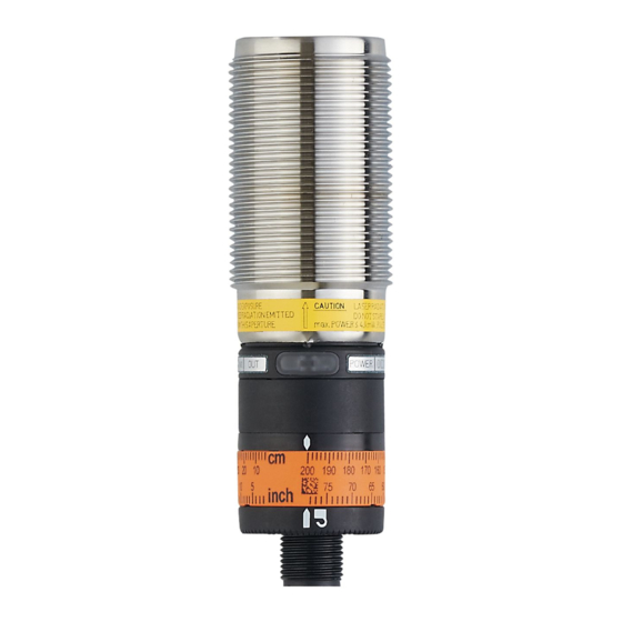
- Page 1 Operating instructions Optical distance sensor OID20x...
- Page 2 Contents 1 Preliminary note ���������������������������������������������������������������������������������������������������3 1�1 Symbols used ������������������������������������������������������������������������������������������������3 2 Safety instructions �����������������������������������������������������������������������������������������������3 3 Functions and features ����������������������������������������������������������������������������������������4 3�1 Applications ���������������������������������������������������������������������������������������������������4 4 Installation������������������������������������������������������������������������������������������������������������5 4�1 Installation conditions ������������������������������������������������������������������������������������5 5 Electrical connection ��������������������������������������������������������������������������������������������5 6 Operating and display elements ��������������������������������������������������������������������������6 7 Settings / operation ����������������������������������������������������������������������������������������������6 7�1 Switch off the laser ���������������������������������������������������������������������������������������6 8 IO-Link �����������������������������������������������������������������������������������������������������������������7 8�1 General information ���������������������������������������������������������������������������������������7...
- Page 3 1 Preliminary note 1.1 Symbols used ► Instructions > Reaction, result […] Designation of keys, buttons or indications → Cross-reference Important note Non-compliance may result in malfunction or interference� Information Supplementary note 2 Safety instructions • Read this document prior to set-up of the unit� Ensure that the product is suitable for your application without any restrictions�...
- Page 4 WARNING Visible laser light; laser protection class 2� Use of controls or adjustments other than those specified herein may result in hazardous radiation exposure� Damage to the retina is possible� ► Do not stare into the laser beam! ► Apply the enclosed labels (laser warning) in the immediate vicinity of the unit� ►...
- Page 5 5: IN = Laser on / off 4: OUT1 = normally open / IO-Link 2: OUT2 = normally closed Core colours of ifm sockets: 1 = BN (brown), 2 = WH (white), 3 = BU (blue), 4 = BK (black), 5 = GR (grey)
- Page 6 6 Operating and display elements 1: LED yellow: Set value reached, output OUT1 = High (if OUT1 is configured as NO) 7 Settings / operation The unit is set via the IO-Link interface. (→ 8 IO-Link) On delivery the unit can also be used without IO-Link� Preset switch point: 2 m ►...
- Page 7 In addition communication is possible via a point-to-point connection with a USB adapter cable� You will find more detailed information about IO-Link at www�ifm�com� 8.2 Device-specific information You will find the IODDs necessary for the configuration of the IO-Link device and detailed information about sensor values, diagnostic information and parameters in the overview table at www�ifm�com�...
Need help?
Do you have a question about the OID20 Series and is the answer not in the manual?
Questions and answers