Table of Contents
Advertisement
Quick Links
Advertisement
Table of Contents

Related Manuals for IFM OID25 Series


Summary of Contents for IFM OID25 Series
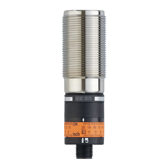
- Page 1 Operating instructions Optical distance sensor OID25x...
- Page 2 Contents 1 Preliminary note ���������������������������������������������������������������������������������������������������3 1�1 Symbols used ������������������������������������������������������������������������������������������������3 2 Safety instructions �����������������������������������������������������������������������������������������������3 3 Functions and features ����������������������������������������������������������������������������������������4 3�1 Applications ���������������������������������������������������������������������������������������������������4 4 Installation������������������������������������������������������������������������������������������������������������5 4�1 Installation conditions ������������������������������������������������������������������������������������5 5 Electrical connection ��������������������������������������������������������������������������������������������5 6 Setting /operation�������������������������������������������������������������������������������������������������6 7 IO-Link �����������������������������������������������������������������������������������������������������������������6 7�1 General information ���������������������������������������������������������������������������������������6 7�2 Device-specific information ����������������������������������������������������������������������������7 7�3 Parameter setting tools ����������������������������������������������������������������������������������7 8 Maintenance, repair, disposal ������������������������������������������������������������������������������7...
-
Page 3: Symbols Used
1 Preliminary note 1.1 Symbols used ► Instructions > Reaction, result […] Designation of keys, buttons or indications → Cross-reference Important note Non-compliance may result in malfunction or interference� Information Supplementary note 2 Safety instructions • Read this document prior to set-up of the unit� Ensure that the product is suitable for your application without any restrictions�... -
Page 4: Functions And Features
Position of the product label Warning sign CLASS 1 TS AA 1301 POWER OID2xx www.ifm.com LASERPRODUCT LASER KLASSE 1 CLASS 1 LASER PRODUCT APPAREIL A LASER CLASSE 1 3 Functions and features The unit is used as an optical distance sensor�... -
Page 5: Electrical Connection
4: OUT1 DC NPN 4: OUT1 = normally open / IO-Link 2: OUT2 = normally closed 2: OUT2 4: OUT1 Core colours of ifm sockets: 1 = BN (brown), 2 = WH (white), 3 = BU (blue), 4 = BK (black) -
Page 6: General Information
The IO-Link interface enables direct access to the sensor values and parameters and provides the possibility to set the parameters of the unit during operation� In addition communication is possible via a point-to-point connection with a USB adapter cable� You will find more detailed information about IO-Link at www�ifm�com�... - Page 7 ► Keep the front lens of the sensor clean� ► After use dispose of the unit in an environmentally friendly way in accordance with the applicable national regulations� ► Do not open the module housing� There are no user-serviceable components inside� Technical data and further information at www�ifm�com...
Need help?
Do you have a question about the OID25 Series and is the answer not in the manual?
Questions and answers