Table of Contents
Advertisement
Quick Links
Advertisement
Table of Contents

Related Manuals for IFM OMH551


Summary of Contents for IFM OMH551
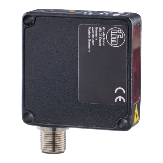
- Page 1 Operating instructions Photoelectric distance sensor OMH551 OMH553 OMH555...
-
Page 2: Table Of Contents
OMH551 OMH553 OMH555 Photoelectric distance sensor Contents Preliminary note ............. - Page 3 Photoelectric distance sensor OMH551 OMH553 OMH555 12 Maintenance, repair and disposal ..........21...
-
Page 4: Preliminary Note
OMH551 OMH553 OMH555 Photoelectric distance sensor 1 Preliminary note You will find instructions, technical data, approvals and further information using the QR code on the unit / packaging or at www.ifm.com. 1.1 Symbols used Requirement Instructions Reaction, result [...] Designation of keys, buttons or indications... -
Page 5: Safety Instructions
Photoelectric distance sensor OMH551 OMH553 OMH555 2 Safety instructions • The unit described is a subcomponent for integration into a system. – The system architect is responsible for the safety of the system. – The system architect undertakes to perform a risk assessment and to create documentation in accordance with legal and normative requirements to be provided to the operator and user of the system. -
Page 6: Intended Use
OMH551 OMH553 OMH555 Photoelectric distance sensor 3 Intended use The device is used as a photoelectric distance sensor. The device continuously detects the distance to the object and generates output signals according to the parameter settings. • The device has an analogue output (4...20mA / 0...10V) and a digital output that can be configured via IO-Link. -
Page 7: Function
Photoelectric distance sensor OMH551 OMH553 OMH555 4 Function 4.1 Switching off the laser The laser can be switched off via the input on pin 5 and via IO-Link. Input signal on pin 5 Laser Low / not used High / not used High 4.2 Operating modes... -
Page 8: Installation
Detection zone Ò Data sheet 5.2 Mounting accessories The device is supplied without mounting accessories. Suitable mounting accessories can be found at www.ifm.com. 5.3 Installation instructions 5.3.1 Avoidance of soiling and ambient light Preferably align photoelectric sensors with the front lens facing downwards or parallel to the earth’s surface. -
Page 9: Electrical Connection
Photoelectric distance sensor OMH551 OMH553 OMH555 6 Electrical connection The device must be connected by a qualified electrician. u Observe the national and international regulations for the installation of electrical equipment. u Ensure voltage supply according to SELV, PELV. OMHxxx: cULus, Supply Class 2 u Disconnect power. -
Page 10: Operating And Display Elements
(4 Hz) Status LED flashing red Error (correctable by the operator) (1 Hz) Troubleshooting (Ò / 20) Status LED is red Serious error u Contact ifm support. Contact at www.ifm.com Status LED is green, [Find me] Function OUT1 and OUT2 (8 Hz) flashing... -
Page 11: Led States Of The Parameters
Photoelectric distance sensor OMH551 OMH553 OMH555 7.2 LED states of the parameters LED behaviour Description Action All LEDs are off The device is in the Run mode. [I] is white Device is in Info mode. Analogue current output (4...20 mA) is activated. -
Page 12: Set-Up
OMH551 OMH553 OMH555 Photoelectric distance sensor 8 Set-up The sensor needs a warm-up period of ≥ 20 min. The performance parameters specified in the data sheet only apply after this warm-up period. On delivery, the parameters are set to the factory setting. -
Page 13: Parameter Setting
Photoelectric distance sensor OMH551 OMH553 OMH555 9 Parameter setting The sensor can be configured via the [●] and [▼] buttons as well as via IO-Link. During parameter setting the device remains internally in the operating mode. It continues its monitoring function with the existing parameters until the change has been completed. -
Page 14: Parameter Setting Via Io-Link
OMH551 OMH553 OMH555 Photoelectric distance sensor Teach end point [MAX]: u Press the button [●] to exit the Run mode. w LED for [MAX] is white. u Place the object for the analogue end point. u Press and hold the [●] button for 2 seconds to teach [MAX]. -
Page 15: Parameter Setting Via Io-Link
Photoelectric distance sensor OMH551 OMH553 OMH555 w Green status LED flashes (1 Hz). w After 10 seconds, the green status LED flashes twice (50 Hz). w The sensor is locked and returns to the Run mode. Unlocking: u Press and hold [●] and [▼] simultaneously for 10 seconds. -
Page 16: Additional Parameter Settings Via Io-Link
OMH551 OMH553 OMH555 Photoelectric distance sensor The two system commands reset the device in a different way. [Reset application]: The parameters of the technology-specific application are set to default values. The identification parameters remain unchanged. An upload to the data memory of the master is carried out, if activated in the port configuration of the master. -
Page 17: Switching Counter
Photoelectric distance sensor OMH551 OMH553 OMH555 • [On_ExtActive / Switch on with external signal active] (via input IN1 at pin 5) • [PDOut / Controlled by PDOut] (via IO-Link communication PDOut) u Select [Parameter] > [Signal]. u Select [Transmitte configuration]. -
Page 18: Setting
OMH551 OMH553 OMH555 Photoelectric distance sensor 10 Setting 10.1 Setting the range via IO-Link 10.1.1 Single point mode SSC active: PDV ≥ SP1 SSC inactive: PDV ≤ SP1 + H 10.1.1.1 Single point mode to smart sensor profile SP1+H teach Normally open: (switch point logic = 0) -
Page 19: Background Suppression
Photoelectric distance sensor OMH551 OMH553 OMH555 10.1.1.3 Background suppression teach Normally open: (switch point logic = 0) SP1 = teach – 2*H Switch-on point SP1 + H Switch-off point Switch point Hysteresis Teach point Background suppression SSC: SwitchingSignalChannel PDV: ProcessDataVariable 10.1.2 Window mode... -
Page 20: Troubleshooting
Supply voltage outside the specification (Ò technical data sheet) If the device behaves unexpectedly or incorrectly: u Disconnect the device from the voltage supply (restart) u Restore factory settings, i.e. delivery status (via IO-Link) If the problems persist: u Contact the ifm support at www.ifm.com. - Page 21 Photoelectric distance sensor OMH551 OMH553 OMH555 12 Maintenance, repair and disposal Faulty sensors must only be repaired by the manufacturer. u Keep the front lens of the sensor clean. u After use dispose of the unit in an environmentally friendly way in accordance with the applicable national regulations.
- Page 22 OMH551 OMH553 OMH555 Photoelectric distance sensor 13 Factory setting IO-Link parameter Parameter function Setting range Factory setting Own setting [P-n] Output polarity [PNP] [NPN] [Mode] Operating mode [Standard] Standard [Power] [Speed] [SSC1.1 Param Sp1] Switch point 1 (3000 ... 8000) * 0.01...
- Page 23 Photoelectric distance sensor OMH551 OMH553 OMH555 IO-Link parameter Parameter function Setting range Factory setting Own setting [SSC1.2 Switch-on de- Switch-on delay (0 … 10000) * 0.001 lay] [SSC1.2 Switch-off de- Switch-off delay (0 … 10000) * 0.001 lay] [FILT] Measured value filter-...
Need help?
Do you have a question about the OMH551 and is the answer not in the manual?
Questions and answers