Advertisement
Quick Links
• Owner's Manual
• Frequently Asked Questions
• Assembly Instructions
• Warranty Information
Manufacturer: Backyard Discovery
Register your new swing set on-line @ www.swingsetsonline.com
(you will also find any updates on assembly instructions and
Features the
Save this assembly manual for future reference in the event that
INS-6012 JAB 10/11/11
3001 North Rouse
Pittsburg, KS 66762
1-800-856-4445
information to order replacement parts)
you need to order replacement parts.
RELEASE "A"
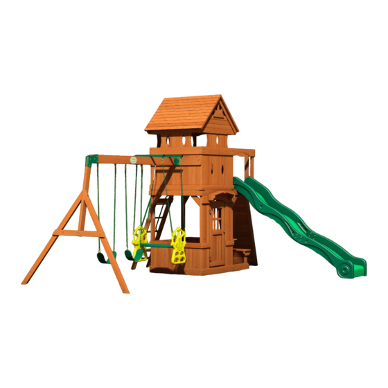
MONTEREY
Wooden Swing Set
Model: #6012
fastening system.
Made in China
Advertisement

Related Manuals for Backyard Discovery Monterey 6012


Summary of Contents for Backyard Discovery Monterey 6012
- Page 1 Model: #6012 • Owner's Manual • Frequently Asked Questions • Assembly Instructions • Warranty Information Manufacturer: Backyard Discovery 3001 North Rouse Pittsburg, KS 66762 1-800-856-4445 Register your new swing set on-line @ www.swingsetsonline.com (you will also find any updates on assembly instructions and...
- Page 2 STOP PARE Missing A Part? CALL US BEFORE GOING BACK TO THE STORE! The store where you made your purchase does not stock parts for this item. If you have assembly questions or if you need parts, whether they are missing or damaged Call Toll-Free Help Line or visit www.swingsetsonline.com "...
- Page 3 Owner’s Manual Play Set Dear Customer: Please read entire booklet completely before beginning the assembly process. Equipment is recommended for use by children 3 to 10 years of age. Structures are not intended for public use. The Company does not warranty any of its residential structures subjected to commercial use such as: Daycare, Preschool, Nursery School, Recreational Park, or any similar Commercial Application.
- Page 4 Owner’s Manual Play Set Please refer to the Assembly section of the Assembly Manual for Maximum Fall Height Positioning Your Playcenter 1. The Playcenter is designed to be installed on a level surface by an Adult with an Adult helper. Place in a flat area of your yard to minimize ground preparation. 2.
- Page 5 Owner’s Manual Play Set The following chart explains the fall height in feet from which a life threatening head injury would not be expected Critical Heights in feet (m) of Tested Materials Material Uncompressed Depth Compressed Depth 6" (152mm) 9" (228mm) 12"...
- Page 6 Owner’s Manual Play Set 17. Instruct children to never crawl on top of a fort roof. 18. Verify that any suspended climbing ropes, chain, or cable are secured at both ends and that they cannot be looped back on it. 19.
- Page 7 Third Party Assembly: Customer may, in their sole discretion, elect to use a third party person or service to assemble this product. Backyard Discovery assumes no responsibility or liability for any charge incurred by the Customer for any assembly services’.
- Page 8 Owner’s Manual Play Set APPENDIX A Information on Playground Surfacing Materials: The following information is from the United States Consumer Product Safety Commission’s Information Sheet for playground surfacing material; also see the following website for additional information: www.cpsc.gov/cpscpub/pubs/323.html. !" #$ "% &...
- Page 9 The stakes provided should be used to secure it firmly to the ground. 2. What size area is recommended for the playset? Backyard Discovery recommends at least a 6’ (six foot) perimeter around and above the playset for maximum safety. 3. What age range is appropriate for the playsets? Backyard Discovery playsets are recommended for children ages 3 –...
- Page 10 11. The end beam is not straight up and down. Why not? This is normal. Backyard Discovery designs playsets this way to ensure the strongest structure possible. The slight angle adds strength and reduces rocking and twisting.
- Page 11 Tools Required for Installation: (These are the tools that are generally required for assembly of our outdoor products. These tools are not included with the outdoor product purchase.) (Square) (Open End Wrenches 1/2") (Level 24") (Tape Measure) (Ladder) (Rubber Mallet - Optional) (Drill Attachments: Phillips (Phillips &...
- Page 12 Basic Setup Dimensions Place the set on level ground, not less than 6 ft [2 m] from any structure or obstruction such as a fence, garage, house, overhanging branches, laundry lines, or electrical wires. " !" $ "& !# ($%& ( !# ($%&...
- Page 13 Parts Identification Wood Components (NOT TO SCALE) A50 - SWING BEAM - W102416 3 3/8"x5 1/4"x89 1/2" (86x134x2274) E1 - FORT UPRIGHT - W102432 1 3/8"x3 3/8"x89 5/8" (36x86x2275) E2 - FORT UPRIGHT - W102433 1 3/8"x3 3/8"x89 5/8" (36x86x2275) E3 - DOUBLE ANGLE GUSSET - W102437 1 3/8"x3 3/8"x15 7/8"...
- Page 14 Parts Identification Wood Components (NOT TO SCALE) G1 - SIDE ARCH WALL RAIL - W102436 1"x5 1/4"x71 7/8" (24x134x1825) G2 - GROUND BOARD - W102438 1"x5 1/4"x43 3/4" (24x134x1110) G3 - WALL RAIL - W102441 1"x5 1/4"x43 3/4" (24x134x1110) G4 - GROUND BOARD - W102450 1"x5 1/4"x63 3/8"...
- Page 15 Parts Identification Wood Components (NOT TO SCALE) G12 - OVERHANG BOARD - W102586 1"x5 1/4"x13 3/4" (24x134x350) G13 - OVERHANG BOARD - W102587 1"x5 1/4"x13 3/4" (24x134x350) G14 - OVERHANG BOARD - W102588 1"x5 1/4"x3 1/2" (24x134x90) G15 - OVERHANG BOARD - W102589 1"x5 1/4"x3 1/2"...
- Page 16 Parts Identification Wood Components (NOT TO SCALE) H10 - ROOF SUPPORT - W102545 1"x3 3/8"x45 1/2" (24x86x1157) H11 - ROOF TRUSS - W102546 1"x3 3/8"x35" (24x86x890) H12 - WALL RAIL - W102558 1"x3 3/8"x43 3/4" (24x86x1110) H13 - LADDER RUNG - W102583 1"x3 3/8"x21 1/8"...
- Page 17 Parts Identification Wood Components (NOT TO SCALE) M8 - WALL SLAT - W102455 5/8"x3 3/8"x55 5/8" (16x86x1414) M9 - WALL RAIL - W102457 5/8"x3 3/8"x40" (16x86x1016) M10 - ARCH WALL SLAT - W102458 5/8"x3 3/8"x42 7/8" (16x86x1090) M11 - ARCH WALL SLAT - W102459 5/8"x3 3/8"x42 7/8"...
- Page 18 Parts Identification Wood Components (NOT TO SCALE) M22 - LOWER ENCLOSURE SLAT - W102515 5/8"x3 3/8"x23" (16x86x583) M23 - ARCH WALL SLAT - W102625 5/8"x3 3/8"x42 7/8" (16x86x1090) M24 - WALL RAIL - W102626 5/8"x3 3/8"x10 7/8" (16x86x276) M25 - UPPER SLAT - W102518 5/8"x3 3/8"x15"...
- Page 19 Parts Identification Wood Components (NOT TO SCALE) N1 - FLOOR BOARD - W102446 5/8"x2 3/8"x34" (16x60x864) N2 - FLOOR BOARD - W102447 5/8"x2 3/8"x25 3/4" (16x60x653) N3 - ROOF BRACE - W102549 5/8"x2 3/8"x32 5/8" (16x60x830) N4 - ROOF BRACE - W102550 5/8"x2 3/8"x34 1/4"...
- Page 20 Parts Identification Hardware (32) F - BOLT WH 5/16x1 - H100008 QG - BOLT WH 5/16x6 - H100023 AE - BOLT WH 5/16x5-3/4 - H100032 (24) CM - BOLT WH 5/16x1/2 - H100115 KT - BOLT WH 1/4x1" - H100137 (13) QD - BOLT WH 5/16x4-1/4 - H100166 (26)
- Page 21 Parts Identification Hardware (44) BW - SCREW PFH 8x3 - H100092 KS - NUT BARREL WH 1/4x5/8" - H100136 (48) CK - SCREW PFH 8x2 - H100111 (136) BS - SCREW PFH 8x1-3/4" - H100089 (22) B - NUT BARREL WH 5/16x5/8 - H100004 (148) BP - SCREW PFH 8x1-1/2"...
- Page 22 Parts Identification Hardware (179) AC - WASHER LOCK EXT 8x19 - H100030 KW - WASHER LOCK EXT 8x15 - H100139 (149) AD - WASHER LOCK EXT 12x19 - H100031 CF - WASHER LOCK INT 10x18 - H100107 (26) CG - WASHER LOCK INT 8x15 - H100108 MC - WASHER LOCK INT 7x12 - H100157 CA - WASHER FLAT 11x25 - H100102 BX - WASHER SPLIT 5/16 - H100095...
- Page 23 Parts Identification Accessories (NOT TO SCALE) - T-40 Torx Driver - A100042 DR - SLIDE RAIL 10' BOTTOM LEFT GREEN - A100030 - T-30 Torx Driver - A100147 DS - SLIDE RAIL 10' BOTTOM RIGHT GREEN - A100031 DT - SLIDE RAIL 10' TOP LEFT GREEN - A100032 TR - SLIDE RAIL 10' TOP RIGHT GREEN - A100033 DX - SLIDE BED 10' LIGHT GREEN - A100035 DN - GLIDER SEAT DARK GREEN - A100025...
- Page 24 Parts Identification Accessories (NOT TO SCALE) EJ - L BRACKET 54x67 -A100053 EV - CLIMBING ROCK - GREEN -A100064 GD - L BRACKET 66x66x127 -A100140 ED - SINGLE DUCTILE HANGER -A100046 EY - TUBING CAP GLIDER SUPPORT -A100067 EX - GLIDER BUSHING BYD GREEN -A100066 EW - GLIDER SUPPORT BYD GREEN - A100065 TD - HINGE (DOOR, SPRING LOADED)
- Page 25 A50 - SWING BEAM - W102416 3 3/8"x5 1/4"x89 1/2" (86x134x2274) TB - SWING BEAM EXTENSION BRACKET - A100325 TC - SWING BEAM EXTENSION BRACKET - A100326 GD - L BRACKET 66x66x127 - A100140 5 FT SWING BEAM EXTENDED STEP 1 ATTACH L BRACKETS GD TO A50 SWING BEAM USING 4-1/4"...
- Page 26 SP50 - SWING BEAM SUPPORT - W102417 E51 - ANGLE BRACE - W100948 3 3/8"x3 3/8"x49 3/8" (86x86x1254) 1 3/8"x3 3/8"x88 3/4" (36x86x2254) E50 - END SUPPORT - W100949 G50 - GROUND BOARD - W100947 1 3/8"x3 3/8"x44 1/8" (36x86x1120) 1"x5 1/4"x86 3/4"...
- Page 27 5 FT SWING BEAM EXTENDED STEP 3 ATTACH SP50 TO TB AND TC EXTENSION BRACKETS USING 3" BOLTS AND 7/8" BARREL NUTS, AS SHOWN. BOLT WH 5/16x3 NUT BARREL WH 5/16x7/8 SP50 SP50 TIGHTEN ALL BOLTS AT THIS TIME.
- Page 28 E72 - LEFT RAIL - W100036 E73 - RIGHT RAIL - W100037 1 3/8"x3 3/8"x61 3/4" (36x86x1570) 1 3/8"x3 3/8"x61 3/4" (36x86x1570) M76 - ROCK WALL BOARD - W100989 M75 - ROCK WALL BOARD - W100988 M74 - ROCK WALL BOARD - W100987 5/8"x3 3/8"x26 5/8"...
- Page 29 N71 - ROCK WALL END BOARD - W100490 5/8"x2 3/8"x27 7/8" (16x60x707) STEP 2 USING N71 AS A GUIDE, PRE-DRILL TOP EDGE OF RAILS WITH 1/8" DRILL BIT. FAILURE TO PRE-DRILL MAY RESULT IN BOARD SPLITTING. ATTACH N71 ROCK WALL END BOARD TO E72 & E73 RAILS USING 1 1/2" SCREWS. SCREW PFH 8x1-1/2"...
- Page 30 EV - CLIMBING ROCK - GREEN - A100064 STEP 3 ATTACH EV ROCKS TO BOARDS USING 1/4"X1 1/4" BOLTS, LOCK WASHERS, AND 1/4" T-NUTS. BOLT PTH (24) 1/4x1-1/4 WASHER (24) LOCK INT 8x15 (24) T-NUT 1/4...
- Page 31 10 FOOT SLIDE ASSEMBLY PHASE 1 STEP 1 PLACE SLIDE BED SUPPORT CENTERED ON THE BOTTOM 1/2" FROM THE EDGE. TRANSFER HOLES ON THE BOARD THROUGH THE SLIDE BED AS SHOWN BELOW. USE A 3/8" DRILL BIT. ATTACH SLIDE BED SUPPORT TO SLIDE USING HARDWARE SHOWN. ITEMS FOR PHASE 1 DESCRIPTION LABEL...
- Page 32 10 FOOT SLIDE ASSEMBLY PHASE 2 STEP 2 ASSEMBLE WITH HARDWARE AS SHOWN. REPEAT ON OTHER SIDE, MAKING A LEFT AND RIGHT ASSEMBLY. ITEMS FOR PHASE 2 DESCRIPTION STOCK NUMBER SLIDE RAIL 10' BOTTOM LEFT GREEN SLIDE RAIL 10' BOTTOM RIGHT GREEN SLIDE RAIL 10' TOP LEFT GREEN SLIDE RAIL 10' TOP RIGHT GREEN BOLT WH 5/16x1/2...
- Page 33 10 FOOT SLIDE ASSEMBLY PHASE 3 STEP 3 PLACE (1) SLIDE RAIL ASSEMBLY ON A FLAT SURFACE AND BEGIN INSERTING SLIDE BED AT THE BOTTOM OF THE SLIDE RAIL (FIG. 1). PUT SLIDE BED SUPPORT INTO THE SUPPORT POCKET AT THE BOTTOM OF THE RAIL AND HAVE A HELPER BEND THE SLIDE BED TOWARDS THE TOP OF THE SLIDE AND INSERT THE BED INTO THE SLIDE CAVITY.
- Page 34 10 FOOT SLIDE ASSEMBLY PHASE 4 STEP 4 ONCE THE SLIDE BED, SUPPORT TUBES, AND SUPPORT BOARD ARE COMPLETELY IN THE CAVITY AND SUPPORT POCKET, SECURE USING 3" SCREWS AT EACH OF THE PILOT HOLE LOCATIONS AS SHOWN. ITEMS FOR PHASE 4 DESCRIPTION STOCK NUMBER SCREW PFH 8x3...
- Page 35 H1 - FLOOR SUPPORT - W102434 G7 - CENTER ARCH WALL RAIL - W102456 G1 - SIDE ARCH WALL RAIL - W102436 1"x3 3/8"x71 7/8" (24x86x1825) 1"x5 1/4"x40 7/8" (24x134x1037) 1"x5 1/4"x71 7/8" (24x134x1825) G4 - GROUND BOARD - W102450 E1 - FORT UPRIGHT - W102432 G6 - GROUND BOARD - W102453 1"x5 1/4"x63 3/8"...
- Page 36 G2 - GROUND BOARD - W102438 G8 - CENTER ARCH WALL RAIL - W102504 M4 - WALL RAIL - W102443 1"x5 1/4"x43 3/4" (24x134x1110) 1"x5 1/4"x43 3/4" (24x134x1110) 5/8"x3 3/8"x43 3/4" (16x86x1110) G3 - WALL RAIL - W102441 H2 - FLOOR SUPPORT - W102439 M21 - WALL RAIL - W102514 H8 - WALL RAIL - W102507 1"x5 1/4"x43 3/4"...
- Page 37 M19 - LADDER WALL CAP - W102512 5/8"x3 3/8"x34" (16x86x863) M22 - LOWER ENCLOSURE SLAT - W102515 M5 - LOWER ENCLOSURE SLAT - W102444 (10) 5/8"x3 3/8"x23" (16x86x583) 5/8"x3 3/8"x23" (16x86x583) M20 - SWING WALL CAP - W102513 5/8"x3 3/8"x40 7/8" (16x86x1038) STEP 4 ATTACH M20 WALL CAP TO M4 WALL RAIL USING 1 3/4"...
- Page 38 M5 - LOWER ENCLOSURE SLAT - W102444 5/8"x3 3/8"x23" (16x86x583) STEP 6 ATTACH (10) M5 WALL SLATS TO M7 WALL RAIL AND G4 GROUND BOARD USING 1 1/8" SCREWS. SCREW PFH (40) 8x1-1/8" STEP 7 ATTACH (12) M5 WALL SLATS TO M4 WALL RAIL AND G2 GROUND BOARD USING 1 1/8" SCREWS.
- Page 39 M18 - TABLE TOP CLEAT - W102510 G9 - TABLE TOP BOARD - W102508 5/8"x3 3/8"x6 1/4" (16x86x160) 1"x5 1/4"x43 3/4" (24x134x1110) E6 - TABLE TOP GUSSET - W102511 1 3/8"x3 3/8"x9 3/8" (36x86x237.5) G10 - TABLE TOP BOARD - W102509 1"x5 1/4"x43 3/4"...
- Page 40 (1) TABLE TOP ASSEMBLY STEP 10 ATTACH TABLE TOP ASSEMBLY FROM STEP 8 TO E6 GUSSETS USING 1 3/4" SCREWS. SCREW PFH 8x1-3/4"...
-
Page 41: Table Of Contents
E3 - DOUBLE ANGLE GUSSET - W102437 1 3/8"x3 3/8"x15 7/8" (36x86x403) STEP 11 ATTACH TOPS OF (2) E3 GUSSETS TO H2 FLOOR SUPPORT USING 2" BOLTS, LOCK WASHERS, AND 7/8" BARREL NUTS; ATTACH AT THE BOTTOM TO E2 UPRIGHTS USING 2" LAG SCREWS AND LOCK WASHERS. -
Page 42: Lag Screw (2) Wh 5/16X2-1/2
H3 - FLOOR JOIST - W102448 1"x3 3/8"x43 5/8" (24x86x1108) STEP 12 USING H8 FLOOR SUPPORT AS A TEMPLATE, PILOT DRILL E72 & E73 ROCK WALL UPRIGHTS WITH AN 1/8" BIT AND ATTACH ROCKWALL ASSEMBLY TO H8 FLOOR SUPPORT USING 2 1/2" LAG SCREWS AND LAG SCREW LOCK WASHERS. -
Page 43: 8X19
M1 - WALL RAIL - W102435 M17 - WALL RAIL - W102506 N1 - FLOOR BOARD - W102446 5/8"x3 3/8"x42 1/8" (16x86x1069) 5/8"x3 3/8"x7 5/8" (16x86x195) 5/8"x2 3/8"x34" (16x60x864) N2 - FLOOR BOARD - W102447 M27 - WALL RAIL - W102520 M6 - FLOOR BOARD - W102445 G11 - WALL RAIL - W102542 (12) -
Page 44: Washer (8) Lock Ext
M2 - WALL RAIL - W102440 M24 - WALL RAIL - W102626 M9 - WALL RAIL - W102457 M10 - ARCH WALL SLAT - W102458 5/8"x3 3/8"x43 3/4" (16x86x1110) 5/8"x3 3/8"x10 7/8" (16x86x276) 5/8"x3 3/8"x40" (16x86x1016) 5/8"x3 3/8"x42 7/8" (16x86x1090) M23 - ARCH WALL SLAT - W102625 EJ - L BRACKET 54x67 - A100053 5/8"x3 3/8"x42 7/8"... -
Page 45: Nut Barrel (8) Wh 5/16X7/8
M10 - ARCH WALL SLAT - W102458 M16 - WALL SLAT - W102505 M28 - DOUBLE ARCH WALL SLAT - W102541 5/8"x3 3/8"x42 7/8" (16x86x1090) 5/8"x3 3/8"x28 1/8" (16x86x715) 5/8"x3 3/8"x42 7/8" (16x86x1090) EJ - L BRACKET 54x67 - A100053 STEP 18 ATTACH TOPS OF M16 WALL SLATS TO G8 WALL RAIL USING 1"... - Page 46 H9 - ROOF SUPPORT - W102543 H12 - WALL RAIL - W102558 H10 - ROOF SUPPORT - W102545 1"x3 3/8"x43 3/4" (24x86x1110) 1"x3 3/8"x43 3/4" (24x86x1110) 1"x3 3/8"x45 1/2" (24x86x1157) STEP 19 ATTACH H9 ROOF SUPPORT TO M10 ARCHED WALL SLATS USING 1" BOLTS, LOCK BOLT WH WASHERS, AND 7/8"...
- Page 47 M13 - WALL SLAT - W102461 M14 - WALL SLAT - W102499 M11 - ARCH WALL SLAT - W102459 M12 - ARCH WALL SLAT - W102460 5/8"x3 3/8"x27" (16x86x685) 5/8"x3 3/8"x42 7/8" (16x86x1090) 5/8"x3 3/8"x42 7/8" (16x86x1090) 5/8"x3 3/8"x42 7/8" (16x86x1090) STEP 21 ATTACH (4) M11 &...
- Page 48 M26 - UPPER ARCHED SLAT - W102519 M13 - WALL SLAT - W102461 M25 - UPPER SLAT - W102518 5/8"x3 3/8"x15" (16x86x380) 5/8"x3 3/8"x27" (16x86x685) 5/8"x3 3/8"x15" (16x86x380) STEP 23 ATTACH (2) M13 WALL SLATS TO G5, M9, & M24 WALL RAILS USING 1 1/8" SCREWS. ATTACH M25 &...
- Page 49 M13 - WALL SLAT - W102461 H11 - ROOF TRUSS - W102546 K1 - MENDING PLATE - W102556 5/8"x3 3/8"x27" (16x86x685) 1"x3 3/8"x35" (24x86x890) 5/8"x5 1/4"x11 3/8" (16x134x290) STEP 25 ATTACH M13 WALL SLATS TO G5 & M9 WALL RAILS AS SHOWN USING 1 1/8" SCREWS. SCREW PFH (16) 8x1-1/8"...
- Page 50 N3 - ROOF BRACE - W102549 N4 - ROOF BRACE - W102550 R1 - ROOF SLAT - W102547 R2 - ARCHED ROOF SLAT - W102548 5/8"x2 3/8"x32 5/8" (16x60x830) (13) 5/8"x2 3/8"x34 1/4" (16x60x870) 3/4"x5 1/2"x50 3/8" (18x140x1280) 3/4"x5 1/2"x50 3/8" (18x140x1280) EJ - L BRACKET 54x67 - A100053 STEP 27 STARTING AT THE PEAK OF THE ROOF, ATTACH R1 ROOF SLAT FLUSH AT THE PEAK...
- Page 51 N5 - GABLE BOARD - W102553 M29 - GABLE BOARD - W102551 K2 - SUNBURST CENTER PIECE - W102557 5/8"x2 3/8"x32" (16x60x813) 5/8"x3 3/8"x45 1/2" (16x86x1157) 5/8"x5 1/4"x13 3/8" (16x134x340) N6 - SUNBURST BOARD - W102554 M30 - GABLE BOARD - W102552 N7 - VERTICAL SUNBURST BOARD - W102555 5/8"x2 3/8"x7 1/2"...
- Page 52 H7 - BENCH SUPPORT - W102501 H6 - BENCH SUPPORT - W102500 Q1 - BENCH BOARD - W102502 M15 - BENCH CLEAT - W102503 1"x3 3/8"x8 5/8" (24x86x220) 1"x3 3/8"x14 1/8" (24x86x360) 1"x4 3/8"x47 1/2" (24x112x1205) 5/8"x3 3/8"x7 7/8" (16x86x200) STEP 31 ATTACH M15 BENCH CLEAT TO (2) Q1 BENCH BOARDS AS SHOWN USING 1 1/8"...
- Page 53 M3 - WALL RAIL - W102442 5/8"x3 3/8"x10 7/8" (16x86x276) (1) BENCH SEAT SUBASSEMBLY STEP 33 ATTACH BENCH SEAT SUBASSEMBLY TO H7 BENCH SUPPORTS AS SHOWN USING 1 3/4" WOOD SCREWS. BENCH SEAT SUBASSEMBLY SCREW PFH 8x1-3/4" STEP 34 ATTACH (2) M3 WALL RAILS TO E1 & E2 FORT UPRIGHTS USING 1 1/2" BOLTS, LOCK BOLT WH WASHERS, AND 7/8"...
- Page 54 H5 - WALL SLAT - W102454 M8 - WALL SLAT - W102455 H16 - WALL SLAT - W102628 1"x3 3/8"x55 5/8" (24x86x1414) 5/8"x3 3/8"x55 5/8" (16x86x1414) 1"x3 3/8"x55 5/8" (24x86x1414) STEP 35 ATTACH H5 & H16 WALL SLATS TO G6 GROUND BOARD AND G7 CENTER ARCH WALL BOLT WH RAIL AS SHOWN USING 1 1/2"...
- Page 55 G15 - OVERHANG BOARD - W102589 H15 - OVERHANG CLEAT - W102627 G14 - OVERHANG BOARD - W102588 1"x5 1/4"x3 1/2" (24x134x90) 1"x3 3/8"x5 1/4" (24x86x134) 1"x5 1/4"x3 1/2" (24x134x90) G13 - OVERHANG BOARD - W102587 G12 - OVERHANG BOARD - W102586 1"x5 1/4"x13 3/4"...
- Page 56 H14 - DOOR STOP - W102590 1"x3 3/8"x4 7/8" (24x86x125) (1) WP1 CABIN DOOR ASSEMBLY STEP 39 ATTACH H14 DOOR STOP TO H5 WALL SLAT AS SHOWN USING 1 1/2" SCREWS. SCREW PFH 8x1-1/2" STEP 40 ATTACH TD HINGES TO WP1 CABIN DOOR ASSEMBLY USING 1" WOOD SCREWS, AS SHOWN.
- Page 57 E7 - LEFT LADDER RAIL - W102584 H13 - LADDER RUNG - W102583 1 3/8"x3 3/8"x64 3/8" (36x86x1634) 1"x3 3/8"x21 1/8" (24x86x536) HZ - KNOB - A100071 STEP 41 ATTACH HZ DOOR KNOB TO WP1 DOOR ASSEMBLY USING 1 3/4" SCREWS, AS SHOWN. SCREW PFH 8x1-3/4"...
- Page 58 E8 - RIGHT LADDER RAIL - W102585 M31 - REAR SUPPORT - W102582 1 3/8"x3 3/8"x64 3/8" (36x86x1634) 5/8"x3 3/8"x22 7/8" (16x86x582) TA - METAL LADDER RAIL - Y35-24.75G - A100324 STEP 43 ATTACH E8 RIGHT LADDER UPRIGHT TO H13 LADDER RUNGS USING 2" SCREWS, AS SHOWN.
- Page 59 (1) SLIDE ASSEMBLY (1) LADDER ASSEMBLY STEP 45 ATTACH LADDER ASSEMBLY TO H4 FLOOR SUPPORT USING 2-1/2" LAG SCREWS AND WASHERS, AS SHOWN. LAG SCREW WH 5/16x2-1/2 WASHER LOCK EXT 8x19 STEP 46 CENTER SLIDE ASSEMBLY IN OPENING. USING SLIDE ASSEMBLY AS A TEMPLATE, DRILL BOLT WH THREE 10 MM HOLES THROUGH THE SLIDE AND THE M6 FLOOR BOARD.
- Page 60 FX - HAND GRIP METAL GREEN 381 c/c - A100118 STEP 47 USING FX METAL HAND GRIPS AS A TEMPLATE, PRE-DRILL USING A 3/8" DRILL BIT AND ATTACH FX METAL HAND GRIPS TO M23 WALL SLATS USING 1/2" BOLTS, LOCK BOLT WH 5/16x1/2 WASHERS &...
- Page 61 EX - GLIDER BUSHING BYD GREEN - A100066 EW - GLIDER SUPPORT BYD GREEN - A100065 EY - TUBING CAP GLIDER SUPPORT - A100067 STEP 49 ATTACH (2) EW GLIDER SUPPORTS TO SWING BEAM ASSEMBLY USING 5-3/4" BOLTS, FLAT WASHERS & 5/16" LOCK NUTS, AS SHOWN. INSERT SWING HANGER QUICK LINK THROUGH EX GLIDER BUSHING AND EW GLIDER SUPPORT AND ATTCH USING FLAT WASHER AND 5/16"...
- Page 62 ED - SINGLE DUCTILE HANGER - A100046 STEP 50 INSERT (8) 3/8" T-NUTS INTO THE TOP EDGE OF THE SWING BEAM ASSEMBLY USING A HAMMER. T-NUT 3/8 ATTACH (4) ED DUCTILE HANGERS TO THE SWING BEAM ASSEMBLY USING 5-3/4" HEX BOLTS AND WASHERS, AS SHOWN.
- Page 63 DN - GLIDER SEAT DARK GREEN - A100025 DP - SWING SEAT GREEN - A100027 EF - CHAIN GREEN 57" - A100047 DO - CAPTAINS GLIDER ARM YELLOW - A100026 EZ - CHAIN GREEN 51.25" - A100068 FA - QUICK LINK - A100069 STEP 51 ATTACH DO CAPTAINS GLIDER ARMS TO DN GLIDER SEAT USING 5-3/4"...
- Page 64 STEP 52 ATTACH SWING BEAM ASSEMBLY TO FORT BY INSERTING 1-1/4" HEX BOLTS, SPLIT WASHERS & FLAT WASHERS THROUGH GD L BRACKET AND G3 WALL RAIL INTO PREVIOUSLY ASSEMBLED T-NUTS, AS SHOWN. BOLT HEX 5/16x1-1/4 WASHER SPLIT 5/16 WASHER FLAT 8x27...
- Page 65 SQ - "A" REVISION TAG - A100314 EH - LTP ID TAG - A100051 STEP 53 ATTACH EH ID PLACARD TO SWING BEAM ASSEMBLY USING 3/4" SCREWS, AS SHOWN. ATTACH SQ REVISION TAG TO FORT ASSEMBLY SCREW PFH USING 5/8" SCREWS, WHERE SHOWN. 8x3/4 SCREW PWH 8x5/8...
- Page 66 KC - METAL GROUND STAKE BROWN - A100178 ANCHORING INSTRUCTIONS NOTE: FAILURE TO USE GROUND STAKES CAN BOLT WH 1/4x1" VOID WARRANTY & CAUSE INJURY! LAG SCREW WH 1/4x1-1/2 *STAKES SHOULD BE PLACED IN CONCRETE* WASHER STAKE A STAKE A LOCK EXT STAKE A 8x15...
- Page 67 Limited Warranty. In addition, Backyard Discovery will replace any parts within the first 30 days from date of purchase found to be missing from or damaged in the original packaging.
Need help?
Do you have a question about the Monterey 6012 and is the answer not in the manual?
Questions and answers