Advertisement
Quick Links
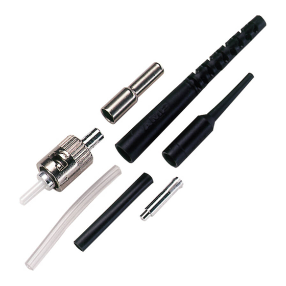
Ferrule
Dust CapG
1. INTRODUCTION
LightCrimp Plus ST Fiber Optic Connector Kit
2064757--1 is designed for use with 125--mm
multimode glass fiber optic cable. This kit can be
used with any of the following media (paragraph of
assembly procedure is indicated next to media).
5.1. 2.0- mm Tight Jacketed Cable
5.2. 2.0- to 2.4- mm Loose Jacketed Cable
With 250- mm or 500- mm Blown Optical Fiber (BOF)
Read these instructions thoroughly before assembling
the connector kit.
All numerical values in this instruction sheet are
NOTE
in metric units. Dimensions are in millimeters
i
[and inches]. Figures are not drawn to scale.
Reasons for reissue of this instruction sheet are
provided in Section 7, REVISION SUMMARY.
2. DESCRIPTION
The connector kit consists of a connector assembly,
crimp eyelet, small white tubing, black tubing, and
strain relief. Also included, assembled onto the
E2009 Tyco Electronics Corporation, Harrisburg, PA
All International Rights Reserved
TE logo and Tyco Electronics are trademarks.
*Trademark. Other products, logos, and company names used are the property of their respective owners.
LightCrimp Plus* ST
Fiber Optic Connector Kit 2064757- 1
Small White
Tubing
Connector
Assembly
TOOLING ASSISTANCE CENTER 1- - 800- - 722- - 1111
PRODUCT INFORMATION 1- - 800- - 522- - 6752
Crimp
Eyelet
Plunger
Dust CapG
G Connector kit is shipped with these installed onto connector
assembly. Keep them in place until ready for assembly.
Figure 1
connector, are dust caps for the ferrule (front of
connector) and plunger (rear of connector). See
Figure 1.
3. SAFETY PRECAUTIONS
Be very careful to dispose of fiber ends properly.
DANGER
The fibers create slivers that can easily puncture
the skin and cause irritation.
NEVER look into the end of terminated or
DANGER
unterminated fibers. Laser radiation is invisible
but can damage eye tissue. NEVER eat, drink, or
smoke when working with fibers. This could lead
to ingestion of glass particles.
DO NOT use defective or damaged components.
CAUTION
Replace them with new components.
!
4. REQUIRED TOOLS AND MATERIALS
— Cable Holder Assembly 492703--1
— Fiber Optic Strip Tool 2064765--1
— Scissors 501014--1
— Alcohol Fiber Wipe Packet 501857--2
This controlled document is subject to change.
For latest revision and Regional Customer Service,
visit our website at www.tycoelectronics.com
Instruction Sheet
408- - 10272
31 AUG 09 Rev C
Strain
Relief
Black
Tubing
1 of 8
LOC B
Advertisement

Related Manuals for Tyco Electronics LightCrimp Plus ST


Summary of Contents for Tyco Electronics LightCrimp Plus ST
- Page 1 1. INTRODUCTION connector, are dust caps for the ferrule (front of connector) and plunger (rear of connector). See LightCrimp Plus ST Fiber Optic Connector Kit Figure 1. 2064757--1 is designed for use with 125--mm multimode glass fiber optic cable. This kit can be 3.
-
Page 2: Preparing The Cable
408- 10272 LightCrimp Plus ST Fiber Optic Connector Kit 2064757- 1 — isopropyl alcohol cable holder. Make sure that the tip of the jacket butts against the end of the channel. — Fiber Optic Cleaver 1871696--3 4. Mark the cable at each cross--slot of the channel. - Page 3 408- 10272 LightCrimp Plus ST Fiber Optic Connector Kit 2064757- 1 7. Using the outer notch of the strip tool, cut 5.2. 2.0- to 2.4- mm Loose Jacketed Cable with through the jacket at each mark. See Figure 3, 250- mm or 500- mm Blown Optical Fiber (BOF) Detail A.
- Page 4 408- 10272 LightCrimp Plus ST Fiber Optic Connector Kit 2064757- 1 Figure 2 A: Preparing the Cable Figure 2 B: Preparing the Cable 2.0- mm Tight Jacketed Cable 2.0- to 2.4- mm Loose Jacketed Cable Detail A Detail A End of Cable Clamp End of Cable 23 cm [9 in.]...
- Page 5 408- 10272 LightCrimp Plus ST Fiber Optic Connector Kit 2064757- 1 Figure 3: Preparing the Cable Figure 4: Preparing the Cable Detail A Detail A Mark Buffer at Cross- - Slots Outer Notch Tip of Buffer Against of Strip Tool...
- Page 6 408- 10272 LightCrimp Plus ST Fiber Optic Connector Kit 2064757- 1 4. Gently close the fiber clamp, and slide the The arrows marked on the front die indicate the CAUTION direction that the ferrule must be pointing when carriage forward. DO NOT touch the button while the connector is positioned in that cavity.
- Page 7 408- 10272 LightCrimp Plus ST Fiber Optic Connector Kit 2064757- 1 Figure 6: Crimping Figure 5: Cleaving Detail A Detail A Stripped Fiber in Slot Buffer Held in Cable Clamp Cleaved End of Fiber Even with Front of Arm of Cable Holder...
-
Page 8: Revision Summary
408- 10272 LightCrimp Plus ST Fiber Optic Connector Kit 2064757- 1 Figure 7: Crimping Figure 8: Crimping Detail A Plunger in First Cavity of Strain Relief Over Crimp Eyelet Front Die with Ferrule and Against Connector Pointed in Direction of Arrow...
Need help?
Do you have a question about the LightCrimp Plus ST and is the answer not in the manual?
Questions and answers