Advertisement
Quick Links
Rear Protective
Cap
Termination
CoverG
Connector Assembly
Connector kit is shipped with these installed onto the connector
G
assembly. Keep them in place until ready for use.
Figure 1
1. INTRODUCTION
This instruction sheet describes the installation of
LightCrimp Plus LC Connectors (Figure 1) to 2.0--mm
loose--jacketed, 900 μm--buffered fiber.
Please read these instructions thoroughly before
starting terminations.
Reasons for revision can be found in Section 7,
REVISION SUMMARY.
2. DESCRIPTION
Each LightCrimp Plus LC Connector consists of a
termination cover, a rear protective cap, the main
connector assembly, the crimp eyelet, and the boot.
Refer to Figure 1 to see these items.
3. SAFETY PRECAUTIONS
To avoid personal injury, ALWAYS wear eye
DANGER
protection when working with optical fibers.
NEVER look into the end of terminated or
unterminated fibers. Laser radiation is invisible
but can damage eye tissue. NEVER eat, drink, or
smoke when working with fibers. This could lead
to ingestion of glass particles.
Be very careful to dispose of fiber ends properly.
DANGER
The fibers create slivers that can easily puncture
the skin and cause irritation.
E2009 Tyco Electronics Corporation, Harrisburg, PA
All International Rights Reserved
TE logo and Tyco Electronics are trademarks.
*Trademark. Other products, logos, and company names used are the property of their respective owners.
LightCrimp* Plus LC
(for Jacketed Cable) Connectors
Boot
Crimp Eyelet
Duplex
Clip
TOOLING ASSISTANCE CENTER 1- - 800- - 722- - 1111
PRODUCT INFORMATION 1- - 800- - 522- - 6752
DO NOT use damaged tools. Replace them with
CAUTION
new components.
!
4. REQUIRED TOOLS AND MATERIALS FOR
ASSEMBLY
Related instruction sheets are listed in
NOTE
parenthesis.
i
Micro--Strip Tool 492109--3 -- 0.008 in.
S
Combination Strip Tool 1278947--1 (408--4577)
S
Cable Holder Assembly 2064540--1 (Used only
S
to terminate connector with cover installed.)
LightCrimp Plus LC, SC, and Splice Die Set
S
with Crimping Tool 2064603--1 (consists of Die
Set 1985766--1 and LightCrimp Termination
Handle ---- PRO--CRIMPER III Hand Tool ----
2064431--1)
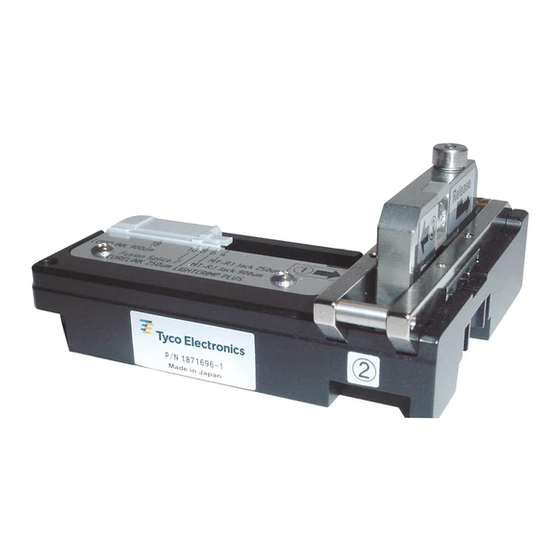
Cleave Tool 1871696--1 (408--10086)
S
Fiber Optic Inspection Microscope Kit
S
1754767--1
Microscope Adapter, 1.25 mm Ferrule
S
1754765--1
Open Ended Wrenches 1278422--1
S
Cable Slitting Tool 2064453--2
S
Alcohol Wipe Packet 501857--2
S
Reagent--grade isopropyl alcohol and lint--free
S
cloths
Shears (KEVLAR cutting) 1278637--1
S
Cable Clamp 1278625--1
S
Termination tools can be found in kits 1754845- - 1
NOTE
and 1754845- - 2.
i
5. ASSEMBLY
5.1. Preparing the Fiber
1. Slide the boot over the jacket as shown in
Figure 2. Place a clamp approximately 200 mm
[8 in.] from the end of the cable ---- behind the boot
(depending on the type of cable used).
This controlled document is subject to change.
For latest revision and Regional Customer Service,
visit our website at www.tycoelectronics.com
Instruction Sheet
408- - 10103
18 AUG 09 Rev E
1 of 6
LOC B
Advertisement

Subscribe to Our Youtube Channel
Related Manuals for Tyco Electronics LightCrimp Plus LC


Summary of Contents for Tyco Electronics LightCrimp Plus LC
- Page 1 1. INTRODUCTION to terminate connector with cover installed.) This instruction sheet describes the installation of LightCrimp Plus LC, SC, and Splice Die Set LightCrimp Plus LC Connectors (Figure 1) to 2.0--mm with Crimping Tool 2064603--1 (consists of Die loose--jacketed, 900 μm--buffered fiber.
- Page 2 408- 10103 LightCrimp Plus LC Connectors Figure 2 Figure 5 2. Place the cable into the cable channel on the 5. Slide the cable into the slitting tool until the cable holder and mark it at the first and second second mark is aligned with the blades as shown in slots as shown in Figure 3.
- Page 3 408- 10103 LightCrimp Plus LC Connectors Mark the Buffer Figure 8 9. Use the combination strip tool to strip the buffer to the first mark. You should strip it in smaller Figure 10 sections multiple times. 3. While applying pressure on the fiber, carefully 10.
- Page 4 408- 10103 LightCrimp Plus LC Connectors 6. Remove the cleaved fiber and properly dispose of the scrap fiber. 5.3. Crimping 1. Place the connector in the holder as shown in Figure 13. Figure 14 6. Gently push the buffer toward the connector...
- Page 5 408- 10103 LightCrimp Plus LC Connectors Figure 18 (Shown While Perfoming the Crimp) 11. Position the connector in the die (as shown in Figure 19) and squeeze the tool handles. 12. Unclamp the jacket and slide the boot onto the back of the connector.
-
Page 6: Revision Summary
408- 10103 LightCrimp Plus LC Connectors 7. REVISION SUMMARY Removed alternate termination method; Removed table in Figure 1 Updated format to current corporate requirements DANGER: Never View Active Fiber Signals 6. AVAILABLE AIDS Professional Fiber Optic Connector Inspection Kit 2064651--[ ] (Instruction Sheet 408--10263)
Need help?
Do you have a question about the LightCrimp Plus LC and is the answer not in the manual?
Questions and answers