Table of Contents
Advertisement
Quick Links
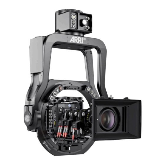
Stabilized Remote Head
SRH-3 & SRH-360
Manual
Date 01.06.2021
Dedicated to these products
KK.0037270
SRH-3 Stabilized Remote Head, No Radio, Set, Standard Joystick
KK.0037271
SRH-3 Stabilized Remote Head, No Radio, Set, Microforce Joystick
KK.0037272
SRH-3 Stabilized Remote Head, No Radio, Set, Broadcast Joystick
Dedicated to these products
KK.0037273
SRH-360 Stabilized Remote Head, No Radio, Set, Standard Joystick
KK.0037275
SRH-360 Stabilized Remote Head, No Radio, Set, Microforce Joystick
KK.0037276
SRH-360 Stabilized Remote Head, No Radio, Set, Broadcast Joystick
SUP 3.0
Advertisement
Table of Contents

Related Manuals for ARRI SRH-360 SUP 3.0


Summary of Contents for ARRI SRH-360 SUP 3.0
- Page 1 Stabilized Remote Head SRH-3 & SRH-360 SUP 3.0 Manual Date 01.06.2021 Dedicated to these products KK.0037270 SRH-3 Stabilized Remote Head, No Radio, Set, Standard Joystick KK.0037271 SRH-3 Stabilized Remote Head, No Radio, Set, Microforce Joystick KK.0037272 SRH-3 Stabilized Remote Head, No Radio, Set, Broadcast Joystick Dedicated to these products KK.0037273 SRH-360 Stabilized Remote Head, No Radio, Set, Standard Joystick...
- Page 2 In no event shall ARRI or its subsidiaries be liable for or have a remedy for recovery of any special, direct, indirect, incidental, or consequential damages, including, but not limited to lost profits, lost...
-
Page 3: Table Of Contents
Table of Contents Table of Contents 1 User Advisory / Application Requirements …………………………………………………. 2 For your safety ………………………………………………………………………………… 3 Generell Functions / Connectors / Available Cables ……………………………………… 4 Remote Head Attachment / Mounting, Securing, ISO Damper ….……….………..……. 11 5 Camera Preparation, Mounting and Balancing / Tilt Lock .……..…….………………….. 13 5 Remote Head Setup ………………………………………………………………………….. -
Page 4: User Advisory / Application Requirements
User Advisory User Advisory / Application Requirements The SRH-3 & SRH-360 stabilized remote head and related products should only be used by experienced and trained operators. This product is not designed for inexperienced users, and must not be used without proper training. -
Page 5: For Your Safety
This product is not designed for inexperienced users and should not and must not be used without proper training. ARRI recommends that all users of the stabilized remote head read the manual in its entirety prior to use. - Page 6 For your safety Safety Instructions DANGER Pay attention during setup and the entire operation that no fingers or limbs end up between the outer yoke and inner ring. A high kinetic force can result between the outer and inner ring, depending on the weight and length of the camera.
-
Page 7: Generell Functions / Connectors / Available Cables
Generell Functions Generell Functions Mounting base for Mitchell Mount Remote Head Front Emergency Stop Switch Base junction box Pan axis Yoke Mount Onboard computer for top support Left junction box Right junction box Tilt motor Camera dovetail plate Mounting platform Side to side adjustment clamp Remote Head Back... - Page 8 Generell Functions Connectors SRH-3 12 Volt high capacity power out LBUS 12/24 Volt RS 24V power out HD SDI In 2 12V Aux FF CAN Bus HD SDI In 1 Right junction box Left junction box CAUTION The 12V aux power consumption should not exceed 14,4V / 5 Amps. Connectors SRH-360 12 Volt high capacity...
- Page 9 Generell Functions Junction Box SRH-3 HD SDI Out 1 Main power in Emergency Shut OFF Switch FS CAN Bus HD SDI Out 2 FF CAN Bus* Junction Box SRH-360 Emergency Main power in Shut OFF Switch FS CAN Bus 12 G HD SDI Out FF CAN Bus* NOTICE * Reserved for future accessories.
- Page 10 Cables Available cables Cam Power, Cine, 12V, XLR, HiCap K2.0010470 Cam Power, Cine, 24V, Fischer 2pin K2.0010471 Cam Power, Cine, 24V, ALEXA Mini K2.0020467 Cam Power, Cine, 12V, HiCap, ALEXA K2.0010538 Cam Power, Cine, 12V, HiCap, ALEXA Mini K2.0010540 Cam Power, Cine, 12V, HiCap, AMIRA, 90° K2.0010565 Cam Power, Cine, 12V, HiCap, Red EPIC K2.0010472...
-
Page 11: Remote Head Attachment / Mounting, Securing, Iso Damper
Remote Head Attachment Remote Head Attachment Mounting the Stabilized Remote Head NOTICE In order to be able to use the maximum stabilization performance of the SRH-3 & SRH-360, the remote head may only be mounted on cranes, dollies, towers, cable cams or other support suitable for use. - Page 12 Remote Head Attachment Vibration Isolator for SRH-3 & SRH-360 The vibration isolator offers Mitchell Mounts at both ends. To support fast and easy mounting of the SRH-3 & SRH-360, the shape of the lower blue Mitchell Mount is optimized for the SRH-3 &...
-
Page 13: Camera Preparation, Mounting And Balancing / Tilt Lock
Step 3 The SAM-1 offers optical-centred mounting of ALEXA Classic, XT and SXT cameras (not ALEXA Studio, ALEXA M or ALEXA65) on the ARRI Trinity and MAXIMA system. €245 The SAM-1 is also compatible with third-Party stabilizer systems fitted with a The right Camera Dovetail Plates and accessories standard 60mm dovetail. -
Page 14: Remote Head Setup
Remote Head Setup Step 5 Clamp Lever Mounting Camera Dovetail Plate (fore and aft adjustment) First open the clamp lever to insert the camera dovetail / SAM plate. Safety Lock To remove the camera dovetail / SAM plate push the blue safety lock. Step 6 Fore and Aft Balance Unlock the tilt lock mechanism first. -
Page 15: Power Supply / Recommended Batteries / Wiring Diagram
Power Supply Powering the SRH-3 & SRH-360 CAUTION To perform in the desired way, the stabilized remote head requires at least min. 24V / 8A over the 3pin XLR plug and min. 12V / 5A via the 4pin XLR plug. Use only suitable and recommended power cords, batteries and power supplies. -
Page 16: Remote Control Panel / Wiring / Functions
(assignable) (assignable) (assignable) (assignable) (assignable) Functions on the rear Main Pwr Emergency On / Off Stop Switch 12V Pwr In 4pin XLR 2pin Mini Lemo Data Pwr Out Functions on the right and left side LBUS In ARRI Mounting Rosettes... -
Page 17: Remote Control Gui / Functions / Emergency Stop
Remote Control GUI Remote Control / GUI (Graphical User Interface) Software factory presets The SRH-3 & SRH-360 has a factory preset for the main functions such as joystick, speed and ramp. The factory preset settings ensure all necessary basic functions and enable immediate operation. - Page 18 Remote Control GUI Step 10 Emergency Stop remote control panel / remote head This information appears on the screen after the emergency stop switch has been triggered. The emergency stop switch can be triggered on the remote control panel and on the remote head.
-
Page 19: Controls Setup / Auto Assignment / Manual Assignment / Available Controllers / Changing Directions / Speed / Ramp
Touch the field below Pan, Tilt, Roll and select the desired controller in the submenu. Available controllers Pan, Tilt, Roll Standard Joystick 1 SJ1T Standard J 1 Tilt DRWP DRW-1 Pan DRW-1, ARRI Wheels, Pan up/down Standard Joystick 1 SJ1P Standard J 1 Pan DRWT DRW-1 Tilt... - Page 20 Controls Setup Changing Direction The marked field indicates the selected direction. Standard J1 Pan Standard J1 Tilt Knob 8 Touching the marked field opens the Direction submenu. Touching the field in the middle toggles between Standard and Reverse. Speed (K1, K2, K3) In factory preset Speed is assigned to: Tilt Roll...
-
Page 21: Pid Setup / Quick Setup
PID / Quick Setup PID / Quick Setup NOTICE It is important to understand and to accept that all necessary steps, such as setting up the camera, attaching the remote head to the crane, the quality of the crane itself and the PID settings, must be taken into account and properly performed. - Page 22 PID / Fine Tuning Step 14 10.3 Fine tuning of the current PID values Set the Joystick Ramp to ZERO (Pan & Tilt) (K4 & K5) Physical test to determine the necessary tilt power value. Touch the lens at the front end, slowly push the camera down and check if the tilt axis starts to slip.
-
Page 23: Drop
Drop Drop Step 15 NOTICE Without any Drop compensation, strong vibrations occur at steep angles. At very steep angles, the weight distribution of the camera setup changes extremely. The weight of the camera remains the same during tilting, but the overall length of the weight distribution becomes shorter and shorter the steeper the tilt angle becomes. -
Page 24: Home Position
Home Position Step 16 Home Position SRH-3 This function moves the remote head back to its predefined starting position. NOTICE Since the SRH-3 has no slip ring and therefore the rotation of the pan axis is limited to +/- 270 °, the mechanical zero / home position must already be considered during the assembly of the SRH-3 on a crane or dolly. -
Page 25: True Horizon
True Horizon / True Tilt True Horizon The True Horizon function, moves the Roll axis back moves the Roll axis back to the set position. When using the DRW-1 wheels or the DEH-1 encoder head, it can be very helpful to return horizon / roll axis to the neutral position by simply pressing a button. -
Page 26: End Stops
End Stops 15 End Stops On / Off NOTICE The End Stops for the Pan axis of the SRH-360 can be enabled only when this axis is operated in speed mode. End Stops N/A Indicates whether end stops / limits values are not set and are therefore not active. -
Page 27: Follow Mode
Follow Mode / Pan Lock 16 Follow Mode On / Off NOTICE This Function is only available in Speed Mode. Indicates if the Follow Mode is active or not. By default, this function is assigned to button B6. Follow Mode / Pan Lock The Follow mode allows the horizontal Pan and the vertical Tilt movement of the remote head to be synchronized with the horizontal Pan and the vertical Tilt movement of the crane. -
Page 28: 17 Dynamic Modes
Dynamic Modes 17 Dynamic Modes The SRH-3 & SRH-360 offer three different Dynamic Modes: Low Dynamic Mode / L. Dyn If the remote head is used on a tripod or dolly and it is important that the head drifts as little as possible, then the Low Dynamic Mode is the right choice. -
Page 29: Additional Controls Setup / Dead Band / Sensitivity / Filter / Ratio
Additional Controls Settings Additional Controls Setup • Dead Band • Sensitivity • Filter • Ratio Select Main Select Position Select the Axis 18.1 Dead Band This value determines when the remote head responds after the control device (joystick) has been moved. NOTICE If the DRW-1 wheels or the DEH-1 encoder head is used as a controller, Dead Band must be set to 0! - Page 30 To simplify the setting, the Ratio settings is assigned to the Speed knobs K1, K2, K3. NOTE To simulate the original gear ratio of the ARRI gear head (slow, medium and fast), you need to set the speed values as shown in the list.
-
Page 31: Additional Remote Head Settings / Pan Motor On/ Off / Motor Mode
Additional Remote Head Settings 19 Additional Remote Head Settings • Pan Motor On / Off • Motor Mode Select Main Select Head 19.1 Pan Motor On / Off Selecting Motor On / Off will toggle between Pan motor On and Off. 19.2 Motor Mode In the Motor Mode column, the motors can be... -
Page 32: External Radio Modules / Setup & Range
External Radio Modules External Radio Modules NOTICE Since 2020, the SRH-3 and SRH-360 remote heads do not have an internal radio system, both remote heads can only be controlled wirelessly via the External Radio Modules. To operate the SRH-3 & SRH-360 without internal radio wireless, the ERM-2400 or ERM-900 must be connected to the remote head and the remote control panel and set up in the radio setup menu. -
Page 33: Fiz Setup Assigning / Available Controllers / Mode / Torque / Calibration / Speed
FIZ Setup Focus - Iris - Zoom / FIZ Introduction Using the optional internal focus wheel or the internal zoom rocker or LBUS-based controls such as Master Grips Focus and Zoom or the OCU-1 allows you to control the cforce mini K0.0019595 KK.0022270 motors or selected broadcast lenses via the... - Page 34 FIZ Setup Step 1 21.4 FIZ Controllers Adjustments • Motor Mode • Calibration • Torque • Speed Select Menu Select FIZ 21.5 Motor Mode In the Motor Mode column, the motors can be changed from Position to Speed mode. Touching the marked area will toggle between Position and Speed mode.
-
Page 35: Profile Management / Selecting Profiles / Cloning Profiles
Profile Management Profile Management 22.1 Selecting Profiles During use, all values, assignments and settings are permanently written to the Standard J1 Pan Standard J1 Tilt Knob 8 current selected profile. In this case in Profile 1. Touching Profile opens a new window where another profile can be selected. 22.2 Cloning Setting In some menus, like PID menu the values can... -
Page 36: Info / Remote Control Panel / Remote Head
Info Info Info Menu Remote / Head 23.1 Remote Control Panel Selecting Remote will provide information about the Mainboard, LBUS, and Expander. 23.2 Mainboard The Mainboard Info Screen will show the actual SW version. 23.3 LBUS The LBUS Info Screen will show the actual SW version of the connected LBUS controller. -
Page 37: Service / Remote Control Panel / Remote Head
Service Service Touching Service opens a new submenu in which you can carry out calibrations and restores for the remote control panel and the remote head. 24.1 Remote Control Panel Selecting Remote will open the remote control panel Service menu. 24.2 Calibrate By selecting Calibrate, internal controllers such as the... - Page 38 Choose Gyro Calibration in order to perform the Camera Gyro calibration. NOTICE Secure the camera. Since the motors are switched off during the calibration, it may be that the camera tilts over the tilt axis. 24.8 Factory Only an ARRI service technician can access this function.
-
Page 39: Power Disconnection
Appendix Power Disconnection CAUTION To disconnect the device safely from the power source, remove both cables from the SRH-3 / SRH-360 remote head. Mount and operate the device in an orientation to ensure easy access to the connectors. Dimensions 26.1 Remote Head SRH-360 Stabilized Axes 3 (Pan, Tilt, Roll) -
Page 40: Pinout
Appendix Pinout RH3 Connectors RH3 Connectors Remote Head SRH-3 SRH-360 / Remote Control Panel V1.4 FF-CAN: 4 POL 12V/ 24V / FS-CAN IN Lötseite Buchse LEMO ECG.3B.305.CLL Lötseite Buchse Fischer DBP 102 A053 - 140 1 = GND 1 = GND 2 = CAN1 L 2 = FOMA BUS Slow L 3 = CAN2 H... -
Page 41: Assignable Controllers & Functions
Additional Joystick 2, Pan, left /right J2 V Joystick 2 V Additional Joystick 2, Tilt, up/down DRWP DRW Pan DRW-1, ARRI Wheels, Pan, Pan, left /right DRWT DRW Tilt DRW-1, ARRI Wheels, Tilt, up/down DRWR DRW Roll DRW-1, ARRI Wheels, Roll... -
Page 42: Declaration Of Conformity
Product Description: Camera Stabilizer System: • ARRI Stabilized Remote Head SRH-360 Pro Set including ARRI Stabilized Remote Head – SRH-360 and ARRI Remote Control Panel – Remote Control-1 & 2 + Europe Setting for Software 01.14.00 or later and Antenna Proant 333 Ex-It 2400 Foldable, Accessories... - Page 43 Kamerastabilisierungssystem / Camera Stabilizer System: • ARRI Stabilized Remote Head SRH-3 Pro Set including ARRI Stabilized Remote Head – SRH-3 and ARRI Remote Control Panel – RCP-1 + Europa Setting der Software 01.14.00 oder höher und Antenne Proant 333 Ex-IT 2400, Zubehör gemäß...
- Page 44 Declaration of Conformity...
Need help?
Do you have a question about the SRH-360 SUP 3.0 and is the answer not in the manual?
Questions and answers