
Related Manuals for ARRI cforce mini RF


Summary of Contents for ARRI cforce mini RF
- Page 1 RF cforce mini RF Software Update Package 1.2 Software Update Package 1.2 U S E R M A N U A L U S E R M A N U A L 14th December 2018 14th December 2018...
- Page 2 Original version. This product was manufactured by ARRI Cine + Video Geräte Ges.m.b.H for Arnold & Richter Cine Technik GmbH & Co. Betriebs KG. For further assistance ARRI Cine + Video Geräte Gesellschaft m.b.H.
- Page 3 Imprint Document revision history Version Order # Release Date 10002881 K5.0016851 F06617 03.05.2018 10002881 K5.0016851 W01412 25.09.2018 10002881 K5.0016851 W01453 14.12.2018...
- Page 4 In no event shall ARRI or its subsidiaries be liable for or have a remedy for recovery of any special, direct, indirect, incidental, or consequential...
- Page 5 or economic loss of any kind or for any claim by a third party, downtime, good-will, damage to or replacement of equipment or property, any cost or recovery of any material or goods associated with the assembly or use of our products, or any other damages or injury of the persons and so on or under any other legal theory.
-
Page 6: Table Of Contents
Contents Contents For your safety..............7 Audience and intended use..........9 Scope of delivery and warranty........10 Introduction..............11 LBUS..............12 Motor layout..............13 Control panel............13 Setup..............14 Status LEDs............18 Motor preparation............19 Compatibility..............22 Sample configurations...........22 Software update............... 25 Power disconnection............26 Appendix................ -
Page 7: For Your Safety
For your safety For your safety Before use, please ensure that all users comprehensively read, understand, and follow the instructions in this document. Risk levels and alert symbols Safety warnings, safety alert symbols, and signal words in these instructions indicate different risk levels: D A N G E R ! DANGER indicates an imminent hazardous situation which, if not avoided, will result in death or serious injury. - Page 8 For operation, always use a power source as indicated in the instructions. Always unplug the cable by gripping the plug, not the cable. Never try to repair. All repair work should be done by a qualified ARRI Service Center. Never remove or deactivate any safety equipment (incl. warning stickers or paintmarked screws).
-
Page 9: Audience And Intended Use
ARRI guidelines. Use the product only for the purpose described in this document. Always follow the valid instructions and system requirements for all equipment involved. The cforce mini RF is solely and exclusively for use on professional camera setups. -
Page 10: Scope Of Delivery And Warranty
19/15mm cforce mini gear 0.8/40t User manual Original packaging Warranty For scope of warranty, please ask your local ARRI Service Partner. ARRI is not liable for consequences from inadequate shipment, improper use, or third- party products. -
Page 11: Introduction
ARRI radio module, eliminating the need for an additional receiver unit mounted on the camera. The cforce mini RF can pair with up to three hand units for split focus, iris and zoom operation and provides full lens data when used with the WCU-4 hand unit. -
Page 12: Lbus
Supports lens data with WCU-4 hand unit Daisy-chainable via LBUS Small and lightweight (~186g/6.56oz incl. gear and antenna) Compatible with all hand units containing ARRI’s white-coded radio module LBUS LBUS is a bus standard designed to allow multiple lens motors and control devices to communicate with each other. -
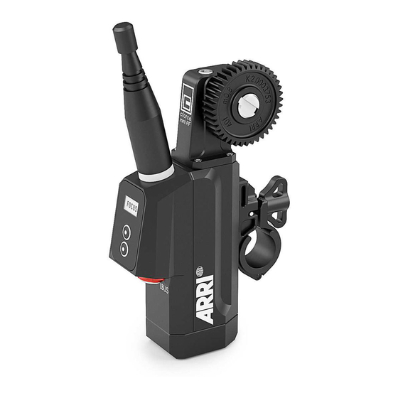
Page 13: Motor Layout
Motor layout Motor layout Antenna Gear Display Upper soft button Lower soft button CAM connector LBUS connector Control panel The cforce mini RF features a user interface to configure the system. The display shows menu and status information. -
Page 14: Setup
Motor layout Soft buttons Two soft buttons are located below the display. They change their behavior depending on the screen content. Menu navigation Use the soft buttons to enter the setup menus as follows: Menu Buttons Press button... Motor axis (FIZ) Upper button short Motor calibration... - Page 15 Select World your specific region is not listed. N O T I C E If the master device (camera) is also equipped with a radio module which is able to set regions, turn off the radio module from the cforce mini RF motor.
- Page 16 Motor layout Region Setting Country code Australia Canada China Egypt Europe Hong Kong India Japan New Zealand Philippines Singapore South Africa South Korea Taiwan Thailand UAE (United Arab Emirates) World WORLD Radio channel The RF menu lets you switch the radio on and off and select the radio channel.
- Page 17 Motor layout RF (Radio) Note Radio=OFF / Mo- tor controller = ON Client Radio = OFF / Mo- tor Controller = OFF Motor behaves like a normal cforce motor without a radio module.
-
Page 18: Status Leds
Motor layout Status LEDs The status LED of the upper button indicates the current motor status: LED (Upper button) Status Solid green Motor is ready and calibrated, no warnings Green flashing Motor is in passive mode Green/red flashing No motor master available (idle) Yellow flashing Motor is currently calibrating Green/yellow flashing... -
Page 19: Motor Preparation
Motor preparation Motor preparation Mounting to 19 mm rods Open the clamp console by turning the thumbscrew counterclockwise. Remove the 19/15mm clamp insert. Attach the clamp console on the rod, with the motor gear engaged to the lens barrel. Close the clamp console by turning the thumbscrew clockwise. Mounting to 15 mm rods Open the clamp console by turning the thumbscrew counterclockwise. - Page 20 Connecting to hand unit Set the hand unit to the same radio channel as the cforce mini RF (refer to user manual of the hand unit). Set the motor side, torque and direction (refer to user manual of the hand unit).
- Page 21 Motor preparation C A U T I O N ! Risk of injury! Do not touch motor gear while motor is pow- ered up! This device is not intended for use by children. Keep body parts out of the motion path. Disconnect the plug if the device is not used for a longer period of time.
-
Page 22: Compatibility
Single Axis Unit SXU-1 For compatibility with cmotion products please contact cmotion directly. Sample configurations cforce mini RF lens motors can be used in different applications, within ARRI systems. The following configurations are samples, making no claim to be exhaustive:... - Page 23 Compatibility cforce mini RF with WCU-4 and up to two additional cforce motors and LCUBE CUB-1 for UDM-1 cforce mini RF with SXU-1 and LCUBE CUB-1 for UDM-1 cforce mini RF with WCU-4 and up to two additional cforce motors...
- Page 24 Compatibility N O T I C E When using the cforce mini RF with ALEXA Mini, switch the motor to client mode in its Radio menu.
-
Page 25: Software Update
The cforce mini RF motor can be updated from external devices through its LBUS interface. To keep your cforce mini RF up-to-date, you may need to update its firmware. Please check ARRI’s website for the latest firmware packages. The following device provide update functionalities for cforce mini RF: •... -
Page 26: Power Disconnection
Power disconnection Power disconnection C A U T I O N ! To disconnect the device safely from the power source, pull the plugs. Mount and operate the device in an orientation that guarantees easy accessible plugs. -
Page 27: 10 Appendix
Appendix 10 Appendix 10.1 Antenna connector The radio connection is established via the antenna mounted to the antenna connector. The radio module inside could be damaged by electrostatic discharge via the open connector. We recommend using the originally supplied antenna only. 10.2 Specifications Electrical data... - Page 28 Appendix Radio system The cforce mini RF motor contains a radio unit that enables wireless lens control with a white coded radio module. A white ring at the base of the antenna mount identifies it. It offers 14 channels to choose from:...
- Page 29 Appendix N O T I C E ARRIs white radio and cmotions red radio are not compatible.
-
Page 30: Dimensions And Weight
Appendix 10.3 Dimensions and weight Dimensions Weight Weight of cforce mini RF: 153g/5,4oz (including cforce mini RF motor unit, cforce mini gear m0.8, 40t and cforce mini clamp console 19/15mm) -
Page 31: Pinouts
Appendix 10.4 Pinouts The cforce mini motor contains one LBUS connector (Lemo 4 pin) and one CAM connector (Lemo 7 pin). LBUS connector CAN-L V-BAT CAN-H CAM connector CAM lf1 (CAN RS232 RX) CAM lf2 (CAN1-L) +V-Bat CAM lf3 (CAN RS232 TX) CAM lf4 (CAN1-H) Cable ID... -
Page 32: Part Numbers
Appendix 10.5 Part numbers cforce mini RF Basic Set KK.0016804 cforce mini RF (Basic Set) The cforce mini RF Basic Set includes: K2.0016802 cforce mini RF motor unit K2.0006176 cforce mini clamp console 19/15mm K2.0006175 cforce mini clamp insert 19/15mm... - Page 33 K2.0002007 Outdoor Antenna (straight) N O T I C E The cforce mini RF Basic Set does not include any LBUS or CAM cables. LBUS cables are available in various lengths and need to be ordered separately. Gears for cforce mini and cforce mini RF K2.0006363...
- Page 34 Appendix K2.0006367 cforce mini gear m0.4/64p, 80t (Pan. iris, Fujinon ENG iris, Canon ENG iris) K2.0006370 cforce mini gear 48p, 60t (Panavision zoom) K2.0006372 cforce mini gear m0.8, 40t, 25mm Part numbers of compatible antennas Radiall/Larsen K2.0002007 Dipole / Reverse SMA Wanshih 50.0013627 Dipole / Reverse SMA...
- Page 35 Appendix Cables and Accessories The following accessories are compatible with the cforce mini RF: K2.0015754 Cable CAM (7p) - RS K2.0015755 Cable CAM (7p) - EXT (16p) K2.0015756 Cable CAM (7p) - EXT (6p) K2.0015757 Cable CAM (7p) - LANC/D-Tap K2.0015758...
-
Page 36: Service Contacts
Appendix 10.6 Service contacts Munich, Germany Vienna, Austria Arnold & Richter Cine Technik ARRI Cine + Video Geräte Ges.m.b.H. +49 89 3809 2121 +43 1 8920107 30 service@arri.de service@arri.at Business hours: Business hours: Mo. - Fr. 9:00 - 17:00 (CET) Mo. -
Page 37: International Declarations
Appendix 10.7 International declarations EU-Declaration of Conformity The designated product conforms with the specifications of the following European directives: Directive 2014/53/EU of the European Parliament and the Council of 16 April 2014 on the harmonization of the laws of the Member States relating to the making available on the market of radio equipment and repealing Directive - OJ L 153, 22.5.2014, S. - Page 38 Réglement sur le matériel brouilleur du Canada. Japan MIC Statement Complies with Ministry of Internal Affairs and Communications notification Article 88, Annex 43. Radio Module The cforce mini RF motor contains the following radio module: FCC ID: Y7N-EMIP400 IC ID: 9482A-EMIP400 CMIT ID: 2017DJ7863C(M)
-
Page 39: Certifications
Appendix MIC ID: 020-180030 NCC: CCAH18LP0660T0 KC: R-CRM-ARg-EMIP400 EMIP400s: ETA:1385/2018/ERLO 10.7.1 Certifications...
Need help?
Do you have a question about the cforce mini RF and is the answer not in the manual?
Questions and answers