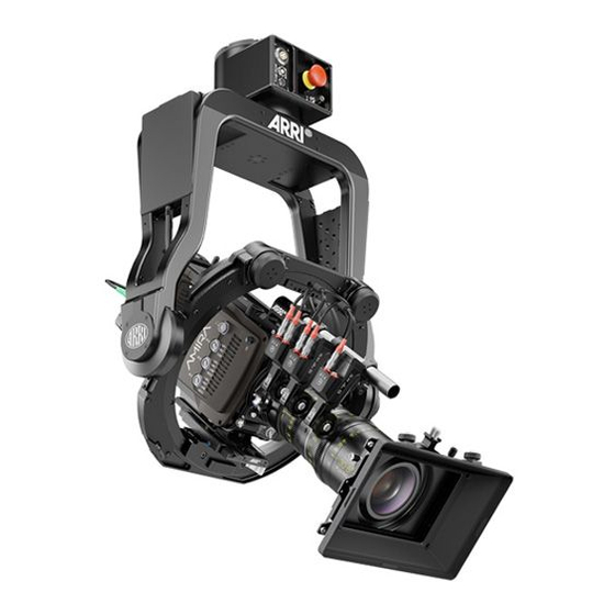
ARRI SRH-3 User Manual
Stabilized remote head
Hide thumbs
Also See for SRH-3:
- User manual (54 pages) ,
- Manual (40 pages) ,
- Troubleshooting manual (9 pages)
Table of Contents
Advertisement
Quick Links
Advertisement
Table of Contents

Subscribe to Our Youtube Channel
Summary of Contents for ARRI SRH-3
- Page 1 ! 1 Stabilized Remote Head SRH-3 USER MANUAL Date 01.09 2018 ...
- Page 2 In no event shall ARRI or its subsidiaries be liable for or have a remedy for recovery of any special, direct, indirect, incidental, or consequential damages, including, but not limited to lost profits, lost savings, lost revenues or economic loss of any kind or for any claim by a third party, downtime, ...
-
Page 3: Table Of Contents
6 Camera Preparation 7 Preparing the Quick Lock Camera Mount 8 Balancing the Camera 9 Powering the SRH-3 10 Dimensions 11 Pinout ... -
Page 4: For Your Safety
and should not and must not be used without proper training. ARRI recommends that all users of the SRH-3 system read the manual in its entirety prior to use. All directions are given from a camera operator's point of view. For example, camera-right side refers to the right side of the camera when standing behind the camera and operating it in a normal fashion. -
Page 5: Functions
! 5 Functions Mounting base Functions Base junction box 2.1 Front Pan axis Onboard computer Yoke Right junction box Left junction box ... -
Page 6: Connectors
! 6 Connectors 2.3 Connectors 2.4 Right junction box 2.5 Left junction box 12 Volt high capacity power out LBUS RS 24V 12/24 Volt power out HD SDI In 2 12V aux HD SDI In 1 FF CAN Bus ... -
Page 7: Safety Instructions
! 7 Safety Instructions Safety Instructions DANGER Pay attention during setup and the entire operation that no fingers or limbs end up between the outer yoke and inner ring. ... -
Page 8: Mounting The Mitchell Mount
DANGER Mounting the the SRH-3 to a crane, dolly, support arm or any other device, has to be done by experienced operator or grip personal. Make sure that all safety regulations have been considered. -
Page 9: Home Position
Before powering the head, align the Home Position Indicator arrows. When initially setting up the SRH-3 on any camera support device, ensure that the home position indicator arrows on the yoke and on the base of the unit are aligned as shown. ... -
Page 10: Camera Preparation
Camera Preparation Camera Preparation Foreword The entire balancing procedure of the SRH-3 stabilized remote head is based on SYMMETRY NEUTRAL BALANCE. NOTE Only a precisely executed camera preparation will enable you to get the best ... - Page 11 Systems (artemis / TRINITY) CAUTION Keep in mind the SRH-3 head is a fully stabilized Gimbal based device with a Product Description/Weight & Dimensions payload capacity of 30kg / 66 lb. The amount of available torque is very high.
-
Page 12: Preparing The Quick Lock Camera Mount
DANGER Ensure that the SRH-3 is switched OFF and that the Tilt Lock is locked. Under no circumstances push fingers or limbs in between the ... -
Page 13: Balancing The Camera
Balancing the Camera DANGER Ensure that the SRH-3 is switched OFF and that the Tilt Lock is UNLOCKED. Under no circumstances push fingers or limbs in between the moving parts of the SRH-3 as this can result in injury. -
Page 14: Powering The Srh-3
CAUTION The SRH-3 head needs to be powered through the 3pin socket with min. 24 Volt / 5 Amps and with 12V through the 4 pin XLR. The power supply for the EUT, has to provide "SELV" and a ... - Page 15 9.4 Power cables for the SRH-3 head: SRH-3, Battery Power Cable, 12V/24V, 0.5m/1.64ft K2.0019306 SRH-3 High Capacity Battery Power Cable 24V, K2.0021427 3pin XLR, 10m/33ft. SRH-3 High Capacity Battery Power Cable 12V, K2.0021428 4pin XLR, 10m/33ft. ...
- Page 16 Wireless Data Wired Note In wireless mode an external 12V power supply is 12V and 24 V needed block batteries Wireless Data Wired Data Note In wireless mode SRH-3 an external 12V power supply power supply is needed...
-
Page 17: Dimensions
THE INFORMATION CONTAINED IN THIS DRAWING IS THE SOLL Material: DWG. NO. PROPERTY OF FoMa Systems GmbH. ANY REPRODUCTION IN CHECKED Remote Head SRH-3 PART OR AS A WHOLE WITHOUT THE WRITTEN PERMISSION OF APPROVED 45,96 FoMa Systems GmbH IS PROHIBITED. -
Page 18: Pinout
RH3 Connectors V1.4 RH3 Connectors Pinout V1.4 Pinout RH3 Connectors RH3 Connectors FF-CAN: 4 POL V1.4 Lötseite Buchse Fischer DBP 102 A053 - 140...


Need help?
Do you have a question about the SRH-3 and is the answer not in the manual?
Questions and answers