ARRI SRH-3 User Manual
Hide thumbs
Also See for SRH-3:
- Manual (40 pages) ,
- User manual (37 pages) ,
- Troubleshooting manual (9 pages)
Table of Contents
Advertisement
Advertisement
Table of Contents

Subscribe to Our Youtube Channel
Related Manuals for ARRI SRH-3


Summary of Contents for ARRI SRH-3
- Page 1 ! 1 Remote Control SRH-3 USER MANUAL Date 01.09.2018 ...
- Page 2 In no event shall ARRI or its subsidiaries be liable for or have a remedy for recovery of any special, direct, indirect, incidental, or consequential damages, including, but not limited to lost profits, lost...
-
Page 3: Table Of Contents
! 3 Table of Contents Table of Contents 1 For your safety 2 Functions 3 Connectors 3 Emergency Shut OFF Switch 4 Home Screen 5 Factory pre assigned controls ... -
Page 4: For Your Safety
and should not and must not be used without proper training. ARRI recommends that all users of the SRH-3 system read the manual in its entirety prior to use. All directions are given from a camera operator's point of view. For example, camera-right side refers to the right side of the camera when standing behind the camera and operating it in a normal fashion. -
Page 5: Functions
Shut OFF Can Pwr Data Switch On/Off 12V RS Antenna Pwr 12V Can Pwr 2.3 Functions on the right and left side LBUS In ARRI Mounting Rosettes... -
Page 6: Connectors
3.2 Hardwiring the SRH-3 Stabilized Remote Head The SRH-3 can be hardwired with the Remote Panel using the FS-CAN BUS connector. NOTE Maximum cable length is 250 meter / 820 feet. FS CAN ... - Page 7 Mini USB socket. Mini 3.6 Antenna This is the connector for the SRH-3 antenna only. NOTICE Never use the Remote Control Panel without an antenna mounted. ...
- Page 8 ! 8 Connectors 3.7 LBUS In The SRH-3 Control Panel offers two LBUS In sockets. Here you can mount up to two ARRI Master Grips or Grips or other supported LBUS products. ...
-
Page 9: Emergency Shut Off Switch
3.8 Emergency Shut OFF Switch The SRH-3 Control Panel offers an Emergency Shut OFF switch. Use the Emergency Shut OFF switch to switch off the motors of the remote head anytime. Camera power will remain on and only the motor power will be disconnected. -
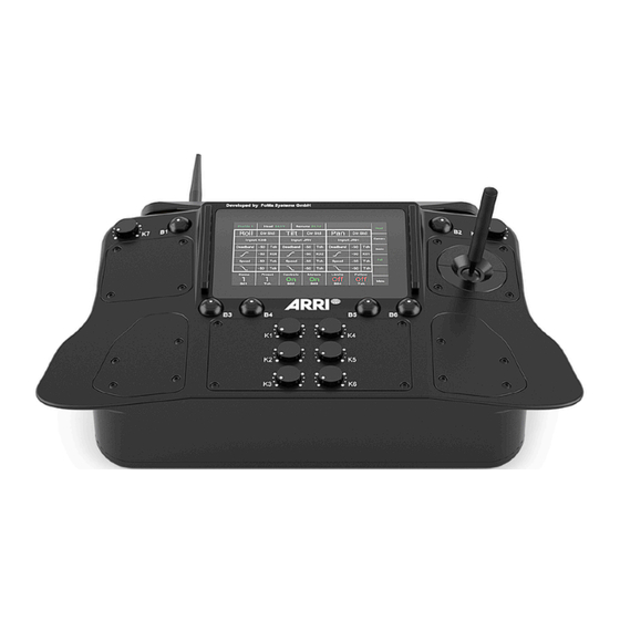
Page 10: Home Screen
Home Screen Home Screen High Power Status Power Status Radio Dynamic Head Panel Signal Directions Status Selected User Profile Selected Menu Axis Indicator Assigned FIZ Home Screen Control Device PID Menu Ramp Start ... - Page 11 11 Home Screen Endstop On/Off Switches and indicates if Endstop settings are on/off. Follow On/Off Switches and indicates if the Follow Mode is on/off. Head Indicates that the head menu is the active menu on the screen. ...
-
Page 12: Factory Pre Assigned Controls
Function / Control Assignment 5.1 Functions You can assign controls or functions to matching knobs, buttons, joysticks or other external controllers. The control assigned to each parameter is displayed on the Home Screen. Functions can be assignment to controls on the unit in the controls page in the Main Menu. ... -
Page 13: Main Menu
Service Selecting Service will open a new touchscreen display menu. The Service menu will allow the operator to restore the SRH-3 to Factory defaults and calibrate joystick and other controllers. - Page 14 Main Menu Selected Profile Head Adjustments System Adjustments Controls Service Adjustment Endstops Info Follow Status Info Selecting Info will open a new touchscreen display menu. The Info menu will display the serial number, hardware version, software version and firmware version of the RH3.
-
Page 15: General Setup
General Setup General Setup 7.1 Mounting Position NOTICE Before using the SRH-3, the mounting position of the head needs to be set in the remote control. NOTE Every time the Head will be switched on this Standing Hanging screen will be shown in the RCP. ... -
Page 16: Pid
In the Motor Mode column the motors can be adjusted from speed to angle measurement. NOTE If you use a Joystick or the ARRI DRW-1 wheels the Motor Mode should be set on Speed. If you use PLC Wheels or rotary Knob, you need to switch ... - Page 17 Proportional – Integral – Derivative controller (PID controller) = Target Position Amount of power = Position needed to move the camera = Actual Position = Target Position Low value slow = Time High value fast = Actual Position = Target Position Cruise control ...
-
Page 18: Pid Quick Setup
Same procedure for Tilt Conclusion: It is important to understand that the entire system, such as camera setup, the attachment of the SRH-3 head to the crane and the overall quality of the crane itself must be considered. For example: ... -
Page 19: Pid Drop
In order to use the maximum power of the SRH-3, it must be ensured that all involved components are optimally designed for the task. If you want to read a truly detailed description of Stabilization as it applies to Film & TV, we strongly recommend the following : http://www.pv-labs.com/wp-content/uploads/2014/12/Stabilization-Steering-and-Gimbal-Technology.pdf... -
Page 20: Pid Autotune
Autotune (Beta) Autotune (Beta) The SRH-3 offers Autotune which will help to find the needed PID values. Autotune tries to calibrate strength and torque of the motors automatically. NOTICE This is a Beta Version! With reference to the BETA END-USER LICENSE AGREEMENT, you must be aware that currently the expected performance may not be fully achieved. -
Page 21: Controls
Controls Menu Controls Selecting Controls on the Main Menu will open a new touchscreen display to allow the operator to assign the functions to each control device and set the characteristics and performance of the assigned control devices. ... - Page 22 PLC VC Wheels, Tilt indicate the current selection VCW Pan PLC VC Wheels, Pan Yellow letters EHDP EHD Pan EHD-1, ARRI Encoder Head, Pan indicate the controller which is assigned currently EHDT EHD Tilt EHD-1, ARRI Encoder Head, Tilt ...
- Page 23 Controls Direction of the controllers This selection will open a new touchscreen that allows to change the direction of the control device from standard to reverse. NOTE The center position shows the actual selection. Touching Rev in this case will reverse the direction of the assigned controller.
- Page 24 Controls Joystick value (Speed) NOTE All three parameters are related to each other. max. 100% If the speed is adjusted to a value below 50, keep the ramp value Speed Value as low as possible. Deadband If the value is to high, there will Stop Ramp Sensitivity...
-
Page 25: Offset
Offset Offset Selecting Offset will open a new touchscreen display submenu named Controls Offset of (Pan/Tilt/Roll). Offset allows the operator to preset a constant rate of movement on a selected axis without any operator input from the controller. - Page 26 Offset 9.2 Direction This selection will open a new touchscreen that allows you to change the direction of the control device from standard to reverse for offset rate. NOTE The center position shows the actual selection. Touching Rev in this case will reverse the direction of the assigned controller.
-
Page 27: Speed & Ratio
Speed & Ratio Speed & Ratio 10.1 Speed Selecting Speed will open a new touchscreen display with a slider to set the speed of the selected axis (Pan/Tilt/Roll). NOTE In the default factory setup the speed adjustments of Pan, Tilt and Roll are assigned to K1, K2 and K3. -
Page 28: Endstops
Endstops Endstops Endstops Selecting Endstops will open a new touchscreen display menu. The Endstops menu will allow the operator to assign end positions for each axis and enable or disable them individually. - Page 29 Endstops NOTE In the default factory setup, the Endstop On/Off button is assigned to B5. The Endstop On/Off button on the Home screen will turn on/off all programmed Endstops. Unassigning will move the function to the touchscreen. ...
-
Page 30: Follow Mode / Pan Lock
Follow mode allows the horizontal pan movement of the head to be synchronized with the horizontal pan movement of the crane. This function is also called Pan Lock. In addition to the Pan Lock, the SRH-3 allows ramps to be defined for the Pan Lock. This allows additional creative possibilities ... - Page 31 Follow NOTE The Follow function can be used to lock a selected axis by turning on the follow function and setting the Speed slider for the selected axis at 100. The Deadband slider should be set at 0 and the Ramp slider set at 0. ...
-
Page 32: True Horizon
True Horizon True Horizon 13.1 Introduction Sometimes the composition of the frame requires manually adjusted horizon and an easy way to get the Roll axis back to the physical Zero position. This is especially important when using wheels for example, or for fast movements. The True Horizon function allows to move the head back into the Zero position ... -
Page 33: Shot Preset
Shot Preset Shot Preset Selecting Shot Presets will open a new touchscreen display menu. The Shot Presets menu will allow you to program up to 12 shot presets for up to 6 parameters including roll, tilt, pan, focus, iris and zoom. These presets can be recalled using the touchscreen Shot Preset button on the home screen. -
Page 34: Status
Status Status Selecting Status will open a new touchscreen display menu. The Status menu will display the status of controller expanders, wireless status, and status of individual connections. (LBUS, FS-CAN Bus, wireless connection) ... - Page 35 Status 15. 2 LBUS Status Display (Remote / Head) The LBUS status row indicates the number of LBUS devices active on the system. Devices indicates how many LBUS controllers are connected to the Remote Panel or the Head ...
-
Page 36: Library
Library Library Selecting Library will open a new touchscreen display menu. The Library menu will store controller setup files, control assignments, motor settings and shot presets. ... -
Page 37: Settings
Settings Settings Selecting Settings will open a new touchscreen display menu. By touching Remote, Head and System a new screen for the Remote, Head and System will open up. ... - Page 38 Settings 17.4 Brightness Wheel Selecting Wheel Brightness will open a new window. 17.5 Settings Head Touching Head will open this screen. Here the status of the mounting position of the head will be displayed and the High Dynamic Mode can be accessed. ...
-
Page 39: Wireless
Make sure that you select the proper area you are operating the device in. NOTE The SRH-3 will be delivered into your region with the required region settings. NOTE The SRH-3 offers 14 channels and will be delivered with an enabled radio connection on channel 13. - Page 40 The extra new channels are placed in between the existing 2.460 GHz EMIP300 channels. To avoid interferences between the 2.465 GHz SRH-3 and WCU-4, ensure that the used frequencies are 2.470 GHz not too close to each other. ...
- Page 41 Wireless NOTICE Wireless region settings specify where the wireless function can be used in compliance with local regulations. It may be illegal to use the wireless function in a region other than specified in the setting. Please ensure that the region is ...
-
Page 42: Service
Service Service Selecting Service will open a new touchscreen display menu. The Service menu will allow the operator to restore the SRH-3 to factory defaults and to calibrate controllers. ... - Page 43 Service 19.4 Service Head 19.5 Restore Factory Defaults Selecting Restore Factory Defaults will open a new touchscreen display menu, here you can restore the head to the factory settings. NOTE The actual settings and values are deleted by the restore! ...
-
Page 44: Info
Info Info Selecting Info will open a new touchscreen display menu. ... - Page 45 Info 20.4 Info Head Mainboard Touching Mainboard, will show you the serial number and firmware version of the remote head. 20.5 Info Head LBUS Touching LBUS, will show you the serial number and firmware version of the cforce motors. ...
-
Page 46: Fiz
Due that the SRH-3 remote control panel and head, supported LBUSe, controllers like the Master Grips, the optional internal Focus wheel and Zoom rocker and cforce lens motors can be used. Adding the LCUBE 2-A, allows to use a selection of broadcast cameras and lenses. ... - Page 47 21.2 FIZ Controls The FIZ home screen can be reached by touching FIZ in the Home Screen. 21.3 Assigning Controllers The FIZ home screen allows to assign the wanted controllers by touching the marked areas. Selecting the marked area will open a new touchscreen ...
- Page 48 21.5 FIZ Controllers Adjustments Selecting FIZ in the Main menu will open a new touchscreen display menu. Motors Motor On/Off Calibration Torque Mode ...
- Page 49 21.7 Torque The Torque selection will open a new touchscreen display with a slider to allow the operator to set the needed Torque for the selected lens motor. ...
-
Page 50: User Profiles
User Profiles User Profiles The SRH-3 RCP allows to store 9 user profiles. The profiles contains all values, assignments and settings for the head, the remote, the used controllers and FIZ. Selected User Profile NOTE In the default factory preset, Profile 1 is selected. - Page 51 User Profiles 22.2 Restore User Profiles To restore all profiles to their factory defaults, go to Service through the Main Menu and select Remote. Touching Factory Default will open a new window Touching Factory Default will open a new window. ...
-
Page 52: Accessories
K2.0001637 is needed. NOTE If users would like a monitor, and the WVR-1 receiver is powered through the SRH-3 remote control, the remote control itself must be powered through the 4pin XLR power in with 12V from an external battery. ... -
Page 53: Assignable Controllers And Functions
VCW Tilt PLC VC Wheels, Tilt VCW Pan PLC VC Wheels, Pan DEHP DEH Pan DEH-1, ARRI Encoder Head, Pan DEHT DEH Tilt DEH-1, ARRI Encoder Head, Tilt Touchscreen Control through RCP K1 … K8 Knob 1 …... -
Page 54: Pinout
Pin Out Pin Out REMOTE Connectors V1.4 FF-CAN Fischer DBP 102 A053 - 140 Lötseite Buchse 1 = GND 2 = CAN1 L 3 = CAN2 H 4 = 12V XLR Power IN 12V RC-Data ( PLC ) Neutrik NC4MP-B...
Need help?
Do you have a question about the SRH-3 and is the answer not in the manual?
Questions and answers