ARRI SRH-3 Manual
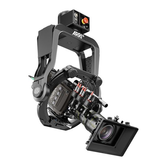
Stabilized remote head
Hide thumbs
Also See for SRH-3:
- User manual (54 pages) ,
- Manual (40 pages) ,
- Troubleshooting manual (9 pages)
Table of Contents
Advertisement
Quick Links
Advertisement
Table of Contents

Subscribe to Our Youtube Channel
Related Manuals for ARRI SRH-3


Summary of Contents for ARRI SRH-3
- Page 1 Stabilized Remote Head SRH-3 SUP 2.2 Manual Date 01.08.2019 ...
- Page 2 In no event shall ARRI or its subsidiaries be liable for or have a remedy for recovery of any special, direct, indirect, incidental, or consequential damages, including, but not limited to lost profits, lost savings, lost revenues or economic loss of any kind or for any claim by a third party, downtime, ...
-
Page 3: Table Of Contents
Table of Contents Table of Contents 1 User Advisory / Application Requirements ………………………………………………. 2 For your safety ……………………………………………………………………………… 3 Functions Head / Connectors ….………………………………………………………….. 4 Remote Head Setup / Top Down, Home Position,Tilt Lock ……..……………….……… 5 Camera Setup / Mounting the Camera / Balancing the Camera ……..…..……..…….. 10 6 Power Supply / Recommended Batteries / Wiring ………………..……………………. -
Page 4: User Advisory / Application Requirements
Drift is normally measured in degrees per hour. The SRH-3 remote head has a very small amount of drift that would only be noticed while the head is stationary over a long period of time. The average drift can be up to approximately 10° in 30 minutes. ... -
Page 5: For Your Safety
ARRI recommends that all users of the SRH-3 stabilized remote head read the manual in its entirety prior to use. All directions are given from a camera operator's point of view. For example, camera-right ... - Page 6 DANGER DANGER Rotating Rotating Parts Parts CAUTION Keep in mind that the SRH-3 stabilized remote head is a fully stabilized Gimbal based device with a payload capacity of 30kg / 66 lb. The amount of available torque is very high.
- Page 7 Remote Head Functions Functions Mounting base 3.1 Base junction box Remote Head Front Pan axis Onboard computer Yoke Right junction box Left junction box ...
- Page 8 Remote Head Functions 3.3 Remote Head Connectors 12 Volt high capacity power out LBUS RS 24V 12/24 Volt power out HD SDI In 2 12V Aux HD SDI In 1 FF CAN Bus Right junction box Left junction box ...
-
Page 9: Remote Head Setup / Top Down, Home Position,Tilt Lock
DANGER Mounting the the SRH-3 stabilized remote head to a crane, dolly, support arm or any other device, has to be done by experienced operator or grip personal. Make sure that all safety regulations have been considered. -
Page 10: Camera Setup / Mounting The Camera / Balancing The Camera
SRH-3 stabilized remote head. SAM-1 offers optical-centred mounting of ALEXA Classic, XT and SXT cameras t ALEXA Studio, ALEXA M or ALEXA65) on the ARRI Trinity and MAXIMA system. €245 SAM-1 is also compatible with third-Party stabilizer systems fitted with a Price List - EU 04/2017 ... - Page 11 Remote Head Setup ! 1 1 Step 6 Fore and Aft Balance Unlock the tilt lock mechanism first. DETAIL MAßSTAB 1 : 1 Open the clamp lever to move the dovetail plate forward or backward. Clamp Lever ...
- Page 12 Remote Control Setup Remote Head Setup ! 1 2 Powering the remote head CAUTION To perform in the desired way, the stabilized remote head requires at least min. 24V / 5A over the 3pin XLR plug and min. 12V / 5A via the 4pin XLR plug. ...
- Page 13 Mini Shut OFF Can Pwr Data Switch On/Off 12V RS Antenna Pwr 12V Can Pwr 7.3 Functions on the right and left side LBUS In ARRI Mounting Rosettes...
-
Page 14: Remote Control Gui
Remote Control GUI ! 1 4 SRH-3 Remote Control / GUI (Graphical User Interface) Button B2 / Assignable Button B1 / Assignable Knob K7 / Assignable Knob K3 / Roll Angle Tilt Button B5 / Button B4 /... - Page 15 Remote Control GUI ! 1 5 Step 9 Connect the remote control hardwired with the remote head Wired FS CAN Bus K2.0019300 K2.0019301 K2.0019302 K2.0033762 Step 10 ...
- Page 16 PID / Quick Setup ! 1 6 PID / Quick Setup Step 12 Camera Weight Preselection To make setting the PID values as easy as possible, the user can select a light or heavy camera preset from the submenu. Touch PID Touch Default Select preset ...
- Page 17 PID / Quick Setup ! 1 7 Check if the camera: • stops at the selected point • whether the camera exceeds the point • whether the camera is bouncing left and right If the camera exceeds the desired point, increase the P and D values in increments of five.
-
Page 18: Controls Setup / Changing Profiles / Auto Assignment / Manual Assignment / 10 Available Controllers / Changing Directions / Speed / Ramp / Default Possition
Touch the field below Pan and select the desired controller in the submenu. DEHP DEH-1 Pan DEH-1, ARRI Encoder Head, Pan Available controllers DEHT DEH-1 Tilt DEH-1, ARRI Encoder Head, Tilt J1 V Joystick 1 V Joystick 1, up/down ... - Page 19 ! 1 9 Controls Setup 10.4 Changing Direction This field indicates the selected direction of the assigned controller. Selecting Dir will open the Direction submenu. Selecting the field in the middle toggles between Standard and Reverse. ...
-
Page 20: Additional Controls Setup / Deadband / Sensitivity / Ramp Mode / Filter / Ratio
Additional Controls Setup ! 2 0 Additional Controls Setup • Deadband • Sensitivity • Ramp Mode • Filter • Ratio Select the Axis Select Main Select Position 11.1 Deadband This value determines when the remote head responds after the control device (joystick) has ... - Page 21 Additional Controls Setup ! 2 1 11.3 Ramp Mode / Dynamic or Constant Selecting the field toggles between Dynamic ramp and Constant ramp. Constant Ramp (preset) will keep the adjusted ramp, regardless of the speed values. Dynamic Ramp The dynamic ramp can only be used when the controller is used in Speed Mode, like the joystick. ...
-
Page 22: Remote Head Setup / Pan Motor On/Off / Motor Mode / Endstops / Follow / True Horizon / High Dynamic Mode / Mounting Position
Remote Head Setup ! 2 2 Remote Head Setup • Pan Motor On/Off • Motor Mode • Endstops / Limits • Follow / Pan Lock • True Horizon • High Dynamic Mode • Mounting Position Select Main Select Head ... - Page 23 Remote Head Setup ! 2 3 12.4 Follow / Pan Lock The Follow mode allows the horizontal Pan and the vertical Tilt movement of the remote head to be synchronised with the horizontal Pan and the vertical Tilt movement of the crane. This function is also called Pan Lock. ...
- Page 24 Remote Head Setup ! 2 4 12.5 True Horizon Sometimes the composition of the frame requires manually adjusted horizon and an easy way to get the Roll axis back True to the physical Zero position. Horizon This is especially important when using wheels, or for fast movements.
-
Page 25: Wireless Setup / Channels / Regions / Range
NOTE Please read the separate manual of the ERM modules. NOTE The SRH-3 remote head and remote control will be delivered into your region with the required region settings and a deactivated radio module. ... - Page 26 Wireless Setup ! 2 6 Step 2 Select Menu Select Settings Select Radio Step 3 Select Internal Radio to activate the internal radio module. Step 4 Selecting Mode will toggle between radio On and radio Off. ...
- Page 27 NOTE 2.450 GHz Make sure that the selected frequencies are not 2.455 GHz too close together to avoid interference between 2.460 GHz the SRH-3 remote control and the WCU-4. 2.465 GHz 2.470 GHz 2.475 GHz ...
- Page 28 FIZ Setup ! 2 8 Focus - Iris - Zoom / FIZ 14.1 Introduction Using the optional internal focus wheel or the internal zoom rocker or LBUS-based controls such as Master Grips Focus and Zoom or the K0.0019595 KK.0022270 OCU-1 allows you to control the cforce mini ...
- Page 29 FIZ Setup ! 2 9 14.2 FIZ Controllers Adjustments • Calibration • Torque • Mode • Speed Select Menu Select FIZ 14.3 Calibration By Selecting Calibrate, every single cforce mini motor will be calibrated. ...
-
Page 30: Fine Trim
FIZ Setup ! 3 0 14.6 Speed (FIZ motor in Speed Mode) NOTE In general, the speed of FIZ motors can only be adjusted while the motor is operating in Speed mode. For example, to adjust the speed of the Zoom motor touch: Menu - FIZ ... - Page 31 Info & Service ! 3 1 Info / Service 15.1 Info Menu Remote / Head Selecting Remote will provide information about the Mainboard, LBUS, and Expander. ...
-
Page 32: Info & Service Factory Defaults / Joystick Calibration / Sensor Calibration
Info & Service ! 3 2 15.3 Joystick Calibration Selecting Calibrate Joystick 1 opens a new submenu in which the internal joystick can be calibrated. 15.4 Service / Remote head Selecting Head will open the head service menu. ... -
Page 33: Profile Management
Profile Management ! 3 3 Profile Management 16.1 Selecting Profiles During use, all values, assignments and settings are permanently written to the selected profile. In this case in Profile 1. Selecting Profile opens a new window where another profile can be selected. 16.2 Startup Settings To ensure that the remote head works properly when it is switched on even when the... -
Page 34: Power Disconnection
CAUTION To disconnect the device safely from the power source, remove both cables from the SRH-3 remote control. Mount and operate the device in an orientation to ensure easy access to the connectors. ... -
Page 35: Pinout
Appendix ! 3 5 RH3 Connectors Pinout Remote Head / Remote Control V1.4 RH3 Connectors V1.4 RH3 Connectors V1.4 RH3 Connectors V1.4 12V/ 24V / FS-CAN IN Lötseite Buchse LEMO ECG.3B.305.CLL FF-CAN: 4 POL Lötseite Buchse Fischer DBP 102 A053 - 140 1 = GND 1 = GND 2 = FOMA BUS Slow L... -
Page 36: Assignable Controllers & Functions
PLC VC Wheels, Roll VCW Tilt PLC VC Wheels, Tilt VCW Pan PLC VC Wheels, Pan DEHP DEH Pan DEH-1, ARRI Encoder Head, Pan DEHT DEH Tilt DEH-1, ARRI Encoder Head, Tilt Touchscreen Control through RCP K1 … K8 Knob 1 … Knob 8 Knobs B1 …... -
Page 37: Declaration Of Conformity
Product Description: Camera Stabilizer System: • ARRI Stabilized Remote Head SRH-3 Pro Set including ARRI Stabilized Remote Head – SRH-3 and ARRI Remote Control Panel – Remote Control-1 + Europe Setting for Software 01.14.00 or later and Antenna Proant 333 Ex-It 2400 Foldable, Accessories regarding... - Page 38 Declaration of Conformity ! 3 8 TRA REGISTERED No : SRH-3: ER72306/19 RDP-1: ER72308/19 DEALER No: DA68290/17 CMIIT ID: 2017DJ7865 (M) CMIIT ID: 2017DJ7863 (M) SRH-3 Pro Set CMIIT ID: 2018DP6608...
- Page 39 Declaration of Conformity ! 3 9 ETA-1386/2018/ERLO ETA-1385/2018/ERLO MIC-ID: 020-180029 020-180030 NCC: CCAH18LP0650TO CCAH18LP0660TO...
- Page 40 Kamerastabilisierungssystem / Camera Stabilizer System: • ARRI Stabilized Remote Head SRH-3 Pro Set including ARRI Stabilized Remote Head – SRH-3 and ARRI Remote Control Panel – RCP-1 + Europa Setting der Software 01.14.00 oder höher und Antenne Proant 333 Ex-IT 2400, Zubehör gemäß...
Need help?
Do you have a question about the SRH-3 and is the answer not in the manual?
Questions and answers