Advertisement
Quick Links
DTP DVI 230 • Setup Guide
This guide provides quick start instructions for an experienced installer to set up and operate the Extron DTP DVI 230 digital video
extender. The DTP DVI 230 transmitter and receiver pair can extend an HDCP-compliant DVI signal up to 230 feet (70 m).
Installation
Step 1 — Mounting
Turn off or disconnect all equipment power sources and mount the Tx and Rx units as required.
DTP DVI 230 Tx
INPUTS
AUDIO
Front
3
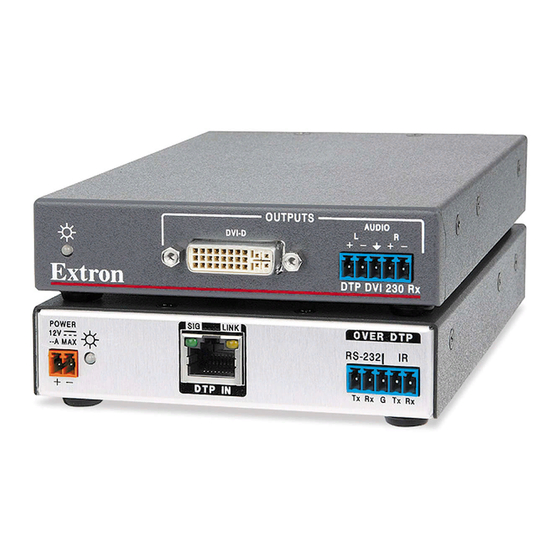
DTP DVI 230 Rx
Front
Step 2 — Connections
a
DVI Input connector (Tx) — Connect an DVI cable between this port and the DVI output port of the digital video source.
b
Local Output connector (Tx) — If desired, connect a DVI monitor for local monitoring of the input digital image.
c
Audio input (Tx) — Connect an unbalanced stereo audio source to this 3.5 mm mini stereo jack for an analog audio input.
d
RS-232 and IR connectors (both units) — To pass serial or infrared data or control signals,
such as serial control of a projector, connect the primary device to the transmitter and the
secondary device to the receiver via the RS-232 and IR captive screw connectors on both
units.
e
DTP RJ-45 connectors (both units) — Connect transmitter DTP Out to receiver DTP In.
Extron recommends that you terminate both cable ends in accordance with the following
specifications, at a minimum:
•
TIA/EIA T 568 B
ATTENTION:
•
Do not connect these devices to a computer data or telecommunications network.
•
Ne connectez pas ces appareils à un réseau de télécommunications ou de données
informatiques..
Sig(nal) LED (both units) — Lights when the unit is receiving a TMDS clock signal on the DVI input
(transmitter) or any valid signal on the DTP In connector (receiver).
Link LED (both units) — Lights when a valid link is established between the units on the DTP cable.
e
DVI Output connector (Rx) — Connect a display with an DVI input for display of the transmitted direct digital image.
f
Audio Output connector (Rx) — Connect a balanced or unbalanced stereo or mono audio device to the receiver via the Audio
captive screw connector. See the
LOCAL OUTPUT
DVI-D
DTP DVI 230 Tx
1
2
OUTPUTS
AUDIO
L
DVI-D
DTP DVI 230 Rx
6
7
•
CAT 6A, shielded
drawing
on page 2.
POWER
12V
0.8 A MAX
Rear
8
POWER
12V
R
0.8 A MAX
Rear
8
•
2 4 AWG, solid conductor
DDC ROUTE
SIG
LINK
REMOTE
ON
1 2
DTP OUT
LOCAL
SHARE
5
SIG
LINK
DTP IN
5
Tx/Rx
Pins
OVER DTP
RS-232
IR
Tx
Rx
G
Tx
Rx
4
OVER DTP
RS-232
IR
Tx
Rx
G
Tx
Rx
4
Connected RS-232
and IR Device Pins
Transmit pin on connected unit
Receive pin on connected unit
Ground
Transmit pin on connected unit
Receive pin on connected unit
Pins:
TIA/EIA T
12345678
568 B
Pin
Wire color
1
White-orange
Orange
2
3
White-green
4
Blue
5
White-blue
Green
6
7
White-brown
8
Brown
TP Wires
1
Advertisement

Related Manuals for Extron electronics DTP DVI 230


Summary of Contents for Extron electronics DTP DVI 230
- Page 1 DTP DVI 230 • Setup Guide This guide provides quick start instructions for an experienced installer to set up and operate the Extron DTP DVI 230 digital video extender. The DTP DVI 230 transmitter and receiver pair can extend an HDCP-compliant DVI signal up to 230 feet (70 m).
- Page 2 No Ground Here Ring Sleeves Sleeves Do not tin the wires! Ring No Ground Here Unbalanced Stereo Output Balanced Stereo Output ATTENTION: Connect the sleeves to the ground contact. DO NOT connect the sleeves to the negative (-) contacts. • •...
Need help?
Do you have a question about the DTP DVI 230 and is the answer not in the manual?
Questions and answers