
Subscribe to Our Youtube Channel
Related Manuals for GEM 649 eSyDrive


Summary of Contents for GEM 649 eSyDrive
- Page 1 GEMÜ 649 eSyDrive Motorized diaphragm valve Operating instructions further information TYPE EL webcode: GW-649 CLASS I AUGUST 2021...
- Page 2 All rights including copyrights or industrial property rights are expressly reserved. Keep the document for future reference. © GEMÜ Gebr. Müller Apparatebau GmbH & Co. KG 27.06.2023 GEMÜ 649 eSyDrive 2 / 50 www.gemu-group.com...
-
Page 3: Table Of Contents
22 Returns ..............Product label ..........23 EU Declaration of Incorporation according to the 5 GEMÜ CONEXO ............ EC Machinery Directive 2006/42/EC, Annex II B ... 6 Reading out the RFID transponder ......24 EU Declaration of Conformity in accordance with 7 Order data ............ -
Page 4: General Information
1.4 Definition of terms Corrosive chemicals! Working medium The medium that flows through the GEMÜ product. Diaphragm size Uniform seat size of GEMÜ diaphragm valves for different Hot plant components! nominal sizes. 1.5 Warning notes Rotating cover! Wherever possible, warning notes are organised according to... -
Page 5: Safety Information
1.4435 (BN2), forged body, Δ Fe < turer first. 0.5 % 1.4435, investment casting In cases of uncertainty: 1.4539, forged body 15. Consult the nearest GEMÜ sales office. CW614N, CW617N (brass) CONEXO dia- phragm RFID chip (see Conexo in- formation) www.gemu-group.com... - Page 6 "OPEN" button Moves actuator to the open position Resets the network alternating settings On-site initialisa- "INIT/CLOSE" but- Moves actuator to the tion (buttons) closed position Starting initialisation Remote initial- isation (via Di- gIn) GEMÜ 649 eSyDrive 6 / 50 www.gemu-group.com...
-
Page 7: Description
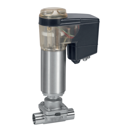
3.1.3.2 High visibility LEDs Location function 3.2 Description The GEMÜ 649 diaphragm valve is actuated by a motorized hollow shaft actuator. It is based on technology that does not use brushes or sensors and therefore guarantees high per- formance and a long service life. In addition to open/close ap- plications, the valve is ideal for variable and complex control applications. - Page 8 Traceability number Consecutive number The month of manufacture is encoded in the traceability num- WARNING ber and can be obtained from GEMÜ. The product was manu- Improper use of the product! factured in Germany. ▶ Risk of severe injury or death The operating pressure stated on the product label applies to ▶...
-
Page 9: Gemü Conexo
RFID chip is used for traceability in the production process and quality assurance. Expansion to include the CONEXO functionality at a later date must be coordinated with GEMÜ. Order with CONEXO GEMÜ CONEXO must be ordered separately with the ordering option "CONEXO"... -
Page 10: Order Data
Spigot ANSI/ASME B36.19M schedule 5s Investment casting material Spigot ANSI/ASME B36.19M schedule 40s 1.4408, investment casting Threaded connection 1.4408, PFA lined Threaded socket DIN ISO 228 1.4435, investment casting NPT female thread Threaded spigot DIN 11851 GEMÜ 649 eSyDrive 10 / 50 www.gemu-group.com... - Page 11 Ra ≤ 0.25 μm (10 µin.) for media wetted surfaces *), 1516 in accordance with DIN 11866 HE5, electropolished internal/external, *) for inner pipe diameters < 6 mm, in the spigot Ra ≤ 0.38 μm www.gemu-group.com 11 / 50 GEMÜ 649 eSyDrive...
-
Page 12: Order Example
Ra ≤ 0.8 µm (30 µin.) for media wetted surfaces, in accordance with DIN 11866 HE3, electropolished internal/external 10 Actuator version Actuator size 2 11 Special version Special version for oxygen, maximum medium temperature: 60 °C 12 CONEXO Without GEMÜ 649 eSyDrive 12 / 50 www.gemu-group.com... -
Page 13: Technical Data
PTFE diaphragms exposed to high temperature fluctuations. The maintenance cycles must be adapted accordingly. GEMÜ 555 and 505 globe valves are particularly suitable for use in the area of steam generation and distribution. The following valve arrangement for interfaces between steam pipes and process pipes has proven itself over time: A globe valve for shutting off steam pipes and a diaphragm valve as an interface to the process pipes. -
Page 14: Pressure
Therefore the Kv values may exceed the tolerance limits of the stand- ard. The Kv value curve (Kv value dependent on valve stroke) can vary depending on the diaphragm material and dur- ation of use. GEMÜ 649 eSyDrive 14 / 50 www.gemu-group.com... -
Page 15: Product Conformity
2014/68/EU ective: Food: Regulation (EC) No. 1935/2004* Regulation (EC) No. 10/2011* FDA* USP* Class VI EMC Directive: 2014/30/EU Drinking water: Belgaqua* * depending on version and / or operating parameters RoHS Directive: 2011/65/EU www.gemu-group.com 15 / 50 GEMÜ 649 eSyDrive... -
Page 16: Mechanical Data
2.80 0.63 1.45 0.88 1.40 0.88 1.66 3.40 1.62 1.32 0.93 1.90 0.93 1.62 4.50 1.50 2.25 1.56 2.70 1.56 2.70 6.30 2.50 2.20 10.30 2.30 MG = diaphragm size, weight in kg GEMÜ 649 eSyDrive 16 / 50 www.gemu-group.com... -
Page 17: Actuator Duty Cycle And Service Life
Input resistance: 250 Ω Accuracy/linearity: ≤ ±0.3% of full flow Temperature drift: ≤ ±0.1% / 10°K Resolution: 12 bit Reverse battery protec- tion: Overload proof: Yes (up to ± 24 V DC) www.gemu-group.com 17 / 50 GEMÜ 649 eSyDrive... - Page 18 Switching voltage: Supply voltage Switching current: ≤ 0.1 A Drop voltage: Max. 2.5 V DC at 0.1 A Overload proof: Yes (up to ± 24 V DC) Short-circuit proof: Pull-Down resistance: 120 kΩ GEMÜ 649 eSyDrive 18 / 50 www.gemu-group.com...
- Page 19 Notes: Moving to the error position is only possible with full power supply. This behaviour is not a safety position. The valve must be operated with a GEMÜ 1571 emergency power supply module (see accessories) to ensure the function in case of voltage loss.
-
Page 20: Electrical Connection
NOTICE Damage to unused plugs due to penetration of humidity! ▶ Unused plugs must be covered with the protective caps supplied with the product to ensure IP protection. Fig. 7: Overview of electrical connections GEMÜ 649 eSyDrive 20 / 50 www.gemu-group.com... - Page 21 GND (actual value output, digital input 1 – 3, er- ror message output) Pin 5 Error message output 24 V DC Pin 6 Digital input 3 Pin 7 Digital input 1 Pin 8 Digital input 2 www.gemu-group.com 21 / 50 GEMÜ 649 eSyDrive...
- Page 22 Default setting 4 - 20 mA GND Sensor supply Adjustable 0 - 20 mA / 0 - 10 V Process actual value (X) 4-pin M12 built-in socket, A-coded Switch Consumer Signal direction Power supply GEMÜ 649 eSyDrive 22 / 50 www.gemu-group.com...
-
Page 23: Dimensions
172.0 243.0 360.0 111.0 134.0 157.0 224.0 296.0 50 - 65 360.0 111.0 134.0 157.0 224.0 296.0 Dimensions in mm MG = diaphragm size * CT = A + H1 (see body dimensions) www.gemu-group.com 23 / 50 GEMÜ 649 eSyDrive... -
Page 24: Body Dimensions
28.0 29.0 30.0 33.7 19.0 120.0 1¼" 25.0 34.0 34.0 35.0 36.0 42.4 26.0 153.0 1½" 25.0 40.0 40.0 41.0 42.0 48.3 26.0 153.0 2" 30.0 52.0 52.0 53.0 54.0 60.3 32.0 173.0 GEMÜ 649 eSyDrive 24 / 50 www.gemu-group.com... - Page 25 Code 60: Spigot ISO 1127/DIN EN 10357 series C (2014 edition)/DIN 11866 series B 2) Valve body material Code 40: 1.4435 (F316L), forged body Code 42: 1.4435 (BN2), forged body, Δ Fe < 0.5% Code C3: 1.4435, investment casting Code F4: 1.4539, forged body www.gemu-group.com 25 / 50 GEMÜ 649 eSyDrive...
- Page 26 Code 65: Spigot ANSI/ASME B36.19M schedule 40s 2) Valve body material Code 40: 1.4435 (F316L), forged body Code 42: 1.4435 (BN2), forged body, Δ Fe < 0.5% Code C3: 1.4435, investment casting Code F4: 1.4539, forged body GEMÜ 649 eSyDrive 26 / 50 www.gemu-group.com...
- Page 27 Code 37: Spigot SMS 3008 2) Valve body material Code 40: 1.4435 (F316L), forged body Code 42: 1.4435 (BN2), forged body, Δ Fe < 0.5% Code C3: 1.4435, investment casting Code F4: 1.4539, forged body www.gemu-group.com 27 / 50 GEMÜ 649 eSyDrive...
- Page 28 = number of flats 1) Connection type Code 1: Threaded socket DIN ISO 228 2) Valve body material Code 12: CW614N, CW617N (brass) Code 37: 1.4408, investment casting Code 90: EN-GJS-400-18-LT (GGG 40.3) GEMÜ 649 eSyDrive 28 / 50 www.gemu-group.com...
- Page 29 Dimensions in mm MG = diaphragm size n = number of flats 1) Connection type Code 31: NPT female thread 2) Valve body material Code 37: 1.4408, investment casting Code 90: EN-GJS-400-18-LT (GGG 40.3) www.gemu-group.com 29 / 50 GEMÜ 649 eSyDrive...
- Page 30 MG = diaphragm size 1) Connection type Code 6: Threaded spigot DIN 11851 2) Valve body material Code 40: 1.4435 (F316L), forged body Code 42: 1.4435 (BN2), forged body, Δ Fe < 0.5% GEMÜ 649 eSyDrive 30 / 50 www.gemu-group.com...
- Page 31 MG = diaphragm size 1) Connection type Code 6K: Cone spigot and union nut DIN 11851 2) Valve body material Code 40: 1.4435 (F316L), forged body Code 42: 1.4435 (BN2), forged body, Δ Fe < 0.5% www.gemu-group.com 31 / 50 GEMÜ 649 eSyDrive...
- Page 32 Code 40: 1.4435 (F316L), forged body Code 42: 1.4435 (BN2), forged body, Δ Fe < 0.5% Code 83: EN-GJS-400-18-LT (GGG 40.3), hard rubber lined Code 90: EN-GJS-400-18-LT (GGG 40.3) Code C3: 1.4435, investment casting GEMÜ 649 eSyDrive 32 / 50 www.gemu-group.com...
- Page 33 Code 40: 1.4435 (F316L), forged body Code 42: 1.4435 (BN2), forged body, Δ Fe < 0.5% Code 83: EN-GJS-400-18-LT (GGG 40.3), hard rubber lined Code 90: EN-GJS-400-18-LT (GGG 40.3) Code C3: 1.4435, investment casting www.gemu-group.com 33 / 50 GEMÜ 649 eSyDrive...
- Page 34 1¼" 38.4 32.0 31.3 64.0 50.5 50.5 26.0 146.0 146.0 146.0 1½" 44.3 38.0 35.6 64.0 50.5 50.5 26.0 159.0 159.0 159.0 2" 56.3 50.0 48.6 77.5 64.0 64.0 32.0 190.0 190.0 190.0 GEMÜ 649 eSyDrive 34 / 50 www.gemu-group.com...
- Page 35 Code 8T: Clamp DIN 32676 series C, face-to-face dimension FTF EN 558 series 7, length only for body configuration D 2) Valve body material Code 40: 1.4435 (F316L), forged body Code 42: 1.4435 (BN2), forged body, Δ Fe < 0.5% Code F4: 1.4539, forged body www.gemu-group.com 35 / 50 GEMÜ 649 eSyDrive...
-
Page 36: Delivery
Only work on plant that has cooled ● chapter "Technical data"). down. 4. Do not store solvents, chemicals, acids, fuels or similar fluids in the same room as GEMÜ products and their spare CAUTION parts. Exceeding the maximum permissible pressure. ▶ Damage to the product Provide precautionary measures against exceeding the ●... -
Page 37: Installation Position
7. Re-attach or reactivate all safety and protective devices. 14.2 Installation position 8. Flush the system. The installation position of the product is optional. 14.5 Installation with threaded sockets 14.3 Installation with clamp connections Fig. 10: Threaded socket Fig. 8: Clamp connection www.gemu-group.com 37 / 50 GEMÜ 649 eSyDrive... -
Page 38: Installation With Threaded Spigots
3. Press the "INIT/CLOSE" button 10. Sealing material ð Network settings are reset in the default settings. ▶ The sealing material is not included in the scope of deliv- ery. Only use appropriate sealing material. ● GEMÜ 649 eSyDrive 38 / 50 www.gemu-group.com... -
Page 39: Commissioning
ð Control on the device is activated. 2. Press the "INIT/CLOSE" button 10. ð The valve moves slowly to the closed position. 3. Also press the "OPEN" button 9. ð The valve moves quickly to the closed position. www.gemu-group.com 39 / 50 GEMÜ 649 eSyDrive... -
Page 40: Inspection And Maintenance
4. Secure the plant or plant component against recommis- Starting point for manual override sioning. 5. Depressurize the plant or plant component. 6. Actuate GEMÜ products which are always in the same po- 5. Turn housing cover 3 anticlockwise. sition four times a year. ð The product opens. -
Page 41: Removing The Actuator
6. Check parts for potential damage, replace if necessary checks regularly and determine the check intervals in ac- (only use genuine parts from GEMÜ). cordance with the conditions of use and/or the regulatory codes and provisions applicable for this application. -
Page 42: Mounting The Actuator
ð Fastening elements may vary depending on the dia- phragm size and/or valve body version. 4. Move the actuator A to the closed position. 5. Open actuator A approx. 20%. 6. Fully tighten the bolts with nuts diagonally. GEMÜ 649 eSyDrive 42 / 50 www.gemu-group.com... -
Page 43: Error Messages
Fig. 16: Position of the status LEDs The user checks the following conditions directly on-site at the valve using LED MODE and LED PWR: Function High visibility LED green orange Error / Error dis- play www.gemu-group.com 43 / 50 GEMÜ 649 eSyDrive... -
Page 44: Troubleshooting
The product is leaking between actuator Mounting parts loose Retighten mounting parts flange and valve body Valve body of the GEMÜ product is leak- Valve body of the GEMÜ product is faulty Check valve body of the GEMÜ product or corroded... -
Page 45: Removal From Piping
3. Disassemble the product. Observe warning notes and goods can be processed only when this note is completed. If safety information. no return delivery note is included with the product, GEMÜ cannot process credits or repair work but will dispose of the 21 Disposal goods at the operator's expense. -
Page 46: Eu Declaration Of Incorporation According To The Ec Machinery Directive 2006/42/Ec, Annex Ii B
EC Machinery Directive 2006/42/EC, Annex II B Machinery Directive introductory text We, the company GEMÜ Gebr. Müller Apparatebau GmbH & Co. KG Fritz-Müller-Strasse 6–8 74653 Ingelfingen-Criesbach, Germany hereby declare under our sole responsibility that the below-mentioned product complies with the relevant essential health and safety requirements in accordance with Annex I of the above-mentioned Directive. -
Page 47: Eu Declaration Of Conformity In Accordance With 2014/30/Eu (Emc Directive)
2014/30/EU (EMC Directive) EMC introductory text We, the company GEMÜ Gebr. Müller Apparatebau GmbH & Co. KG Fritz-Müller-Strasse 6–8 74653 Ingelfingen-Criesbach, Germany hereby declare under our sole responsibility that the below-mentioned product complies with the regulations of the above-men- tioned Directive. -
Page 48: Eu Declaration Of Conformity In Accordance With 2014/68/Eu (Pressure Equipment Directive)
Information for products with a nominal size ≤ DN 25: The products are developed and produced according to GEMÜ's in-house process instructions and standards of quality which comply with the requirements of ISO 9001 and ISO 14001. According to Article 4, Paragraph 3 of the Pressure Equipment Direct- ive 2014/68/EU, these products must not be identified by a CE-marking. -
Page 49: Eu Declaration Of Conformity In Accordance With 2011/65/Eu (Rohs Directive)
In accordance with 2011/65/EU (RoHS Directive) EMC introductory text We, the company GEMÜ Gebr. Müller Apparatebau GmbH & Co. KG Fritz-Müller-Strasse 6–8 74653 Ingelfingen-Criesbach, Germany hereby declare under our sole responsibility that the below-mentioned product complies with the regulations of the above-men- tioned Directive. - Page 50 GEMÜ Gebr. Müller Apparatebau GmbH & Co. KG Fritz-Müller-Straße 6-8, 74653 Ingelfingen-Criesbach, Germany Subject to alteration Phone +49 (0) 7940 1230 · info@gemue.de www.gemu-group.com 06.2023 | 88614490...
Need help?
Do you have a question about the 649 eSyDrive and is the answer not in the manual?
Questions and answers