
Related Manuals for GEM 649 eSyDrive


Summary of Contents for GEM 649 eSyDrive
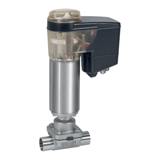
- Page 1 GEMÜ 649 eSyDrive Motorized diaphragm valve Operating instructions further information webcode: GW-649...
- Page 2 All rights including copyrights or industrial property rights are expressly reserved. Keep the document for future reference. © GEMÜ Gebr. Müller Apparatebau GmbH & Co. KG 07.04.2021 GEMÜ 649 eSyDrive 2 / 48 www.gemu-group.com...
-
Page 3: Table Of Contents
Product label ............(Pressure Equipment Directive) ......... 46 4 Correct use ............... 26 Declaration of conformity according to 2014/30/EU 5 GEMÜ CONEXO ............(EMC Directive) ............47 6 Reading out the RFID transponder ......7 Order data ..............10 Order codes ............10 Order example ............. -
Page 4: General Information
1.4 Definition of terms Danger of explosion! Working medium The medium that flows through the GEMÜ product. Diaphragm size Uniform seat size of GEMÜ diaphragm valves for different Corrosive chemicals! nominal sizes. 1.5 Warning notes Hot plant components! Wherever possible, warning notes are organised according to... -
Page 5: Safety Information
14. Do not carry out any maintenance work and repairs not de- LED, manual override scribed in this document without consulting the manufac- and on-site control turer first. In cases of uncertainty: 15. Consult the nearest GEMÜ sales office. www.gemu-group.com 5 / 48 GEMÜ 649 eSyDrive... - Page 6 Moves actuator to the closed position Manual opera- Starting initialisation tion Actuator switched off (OFF mode) Manual opera- tion (on-site) Software update alternating On-site initialisa- tion (buttons) Remote initial- isation (via Di- gIn) GEMÜ 649 eSyDrive 6 / 48 www.gemu-group.com...
-
Page 7: Function
3.1.3.2 High visibility LEDs 3.2 Description The GEMÜ 649 diaphragm valve is actuated by a motorized hollow shaft actuator. It is based on technology that does not use brushes or sensors and therefore guarantees high per- formance and a long service life. In addition to OPEN/CLOSE applications, the valve is ideal for variable and complex con- trol applications. -
Page 8: Correct Use
Traceability number Consecutive number The month of manufacture is encoded in the traceability num- ber and can be obtained from GEMÜ. The product was manu- factured in Germany. The operating pressure stated on the product label applies to a media temperature of 20 °C. The product can be used up to the maximum stated media temperature. -
Page 9: Reading Out The Rfid Transponder
ð The data that is read out is transferred to the CONEXO app. 4. Scan as many components as required. 5. Hold down the On/Off key 4 for at least three seconds. ð The CONEXO pen has been switched off. www.gemu-group.com 9 / 48 GEMÜ 649 eSyDrive... -
Page 10: Order Data
Ra ≤ 0.8 µm (30 µin.) for media wetted surfaces, 1502 face-to-face dimension FTF EN 558 series 1, ISO in accordance with DIN 11866 H3, 5752, basic series 1, mechanically polished internal length only for body configuration D GEMÜ 649 eSyDrive 10 / 48 www.gemu-group.com... - Page 11 Ra max. 0.64 µm (25 µin.) for media wetted sur- faces, in accordance with ASME BPE SF6, electropolished internal/external 10 Actuator version Code Actuator size 0 Actuator size 1 Actuator size 2 2 A www.gemu-group.com 11 / 48 GEMÜ 649 eSyDrive...
-
Page 12: Order Example
Ra ≤ 0.8 µm (30 µin.) for media wetted surfaces, in accordance with DIN 11866 HE3, electropolished internal/external 10 Actuator version 2 A Actuator size 2 11 Special version Special version for oxygen, maximum medium temperature: 60 °C 12 CONEXO Without GEMÜ 649 eSyDrive 12 / 48 www.gemu-group.com... -
Page 13: Technical Data
PTFE diaphragms exposed to high temperature fluctuations. The maintenance cycles must be adapted accordingly. GEMÜ 555 and 505 globe valves are particularly suitable for use in the area of steam generation and distribution. The following valve arrangement for interfaces between steam pipes and process pipes has proven itself over time: A globe valve for shutting off steam pipes and a diaphragm valve as an interface to the process pipes. -
Page 14: Pressure
Interference emission EN 61800-3 Category The product is intended for operation in industrial environments. Food: Regulation (EC) No. 1935/2004* Regulation (EC) No. 10/2011* FDA* USP* Class VI * depending on version and/or operating parameters GEMÜ 649 eSyDrive 14 / 48 www.gemu-group.com... -
Page 15: Mechanical Data
8 Technical data 8.5 Mechanical data Weight: Actuator Actuator version 0A 1.8 kg Actuator version 1A 3.0 kg Actuator version 2A 9.0 kg Body www.gemu-group.com 15 / 48 GEMÜ 649 eSyDrive... -
Page 16: Electrical Data
Reverse battery protec- tion: Overload proof: Yes (up to ± 24 V DC) 8.6.2 Digital input signals Digital inputs: Function: selectable using software Voltage: 24 V DC Logic level "1": >14 V DC GEMÜ 649 eSyDrive 16 / 48 www.gemu-group.com... - Page 17 Switching voltage: Supply voltage Switching current: ≤ 0.1 A Drop voltage: Max. 2.5 V DC at 0.1 A Overload proof: Yes (up to ± 24 V DC) Short-circuit proof: Pull-Down resistance: 120 kΩ www.gemu-group.com 17 / 48 GEMÜ 649 eSyDrive...
- Page 18 The actuator and the PC must be in the same network to use the web server. The IP address of the actuator is entered in the web browser and the actuator can then be parametrised. In order to use more than one actuator, a definitive IP address must be assigned to each actuator in the same network. 8.6.6 GEMÜ 649 eSyDrive 18 / 48 www.gemu-group.com...
-
Page 19: Dimensions
132.0 172.0 243.0 360.0 124.0 134.0 157.0 224.0 296.0 50, 65 360.0 124.0 134.0 157.0 224.0 296.0 Dimensions in mm, MG = diaphragm size * CT = A + H1 (see body dimensions) www.gemu-group.com 19 / 48 GEMÜ 649 eSyDrive... -
Page 20: Body Dimensions
Code 17: Spigot EN 10357 series A (formerly DIN 11850 series 2)/DIN 11866 series A Code 18: Spigot DIN 11850 series 3 Code 60: Spigot ISO 1127/EN 10357 series C/DIN 11866 series B GEMÜ 649 eSyDrive 20 / 48 www.gemu-group.com... - Page 21 26.0 42.2 2.77 42.2 3.56 1½" 153.0 25.0 26.0 26.0 38.10 1.65 48.3 2.77 48.3 3.68 2" 173.0 30.0 32.0 32.0 50.80 1.65 60.3 2.77 60.3 3.91 2½" 173.0 30.0 34.0 63.50 1.65 www.gemu-group.com 21 / 48 GEMÜ 649 eSyDrive...
- Page 22 30.0 32.0 32.0 50.8 60.5 2.80 51.0 2½" 173.0 30.0 34.0 63.5 63.5 1) Connection type Code 35: Spigot JIS-G 3447 Code 36: Spigot JIS-G 3459 schedule 10s Code 37: Spigot SMS 3008 GEMÜ 649 eSyDrive 22 / 48 www.gemu-group.com...
- Page 23 18.0 140.0 G 1½ 56.3 28.8 18.0 140.0 55.0 73.0 35.0 18.0 165.0 71.3 36.0 26.0 165.0 70.0 n = number of flats 1) Connection type Code 1: Threaded socket DIN ISO 228 www.gemu-group.com 23 / 48 GEMÜ 649 eSyDrive...
- Page 24 9 Dimensions 9.2.5 GEMÜ 649 eSyDrive 24 / 48 www.gemu-group.com...
- Page 25 Rd 65 x 1/6 160.0 160.0 32.0 50.0 Rd 78 x 1/6 191.0 191.0 1) Valve body material Code 40: 1.4435 (F316L), forged body Code 42: 1.4435 (BN2), forged body, Δ Fe < 0.5% www.gemu-group.com 25 / 48 GEMÜ 649 eSyDrive...
- Page 26 9 Dimensions 9.2.7 GEMÜ 649 eSyDrive 26 / 48 www.gemu-group.com...
- Page 27 Code 39: 1.4408, PFA lined Code 40: 1.4435 (F316L), forged body Code 42: 1.4435 (BN2), forged body, Δ Fe < 0.5% Code 83: EN-GJS-400-18-LT (GGG 40.3), hard rubber lined Code C3: 1.4435, investment casting www.gemu-group.com 27 / 48 GEMÜ 649 eSyDrive...
- Page 28 Code 39: 1.4408, PFA lined Code 40: 1.4435 (F316L), forged body Code 42: 1.4435 (BN2), forged body, Δ Fe < 0.5% Code 83: EN-GJS-400-18-LT (GGG 40.3), hard rubber lined Code C3: 1.4435, investment casting GEMÜ 649 eSyDrive 28 / 48 www.gemu-group.com...
- Page 29 48.6 64.0 190.0 2½" 34.0 60.3 77.5 216.0 1) Valve body material Code 40: 1.4435 (F316L), forged body Code 42: 1.4435 (BN2), forged body, Δ Fe < 0.5% Code F4: 1.4539, forged body www.gemu-group.com 29 / 48 GEMÜ 649 eSyDrive...
- Page 30 GEMÜ 649 eSyDrive 30 / 48 www.gemu-group.com...
- Page 31 10.2 Connection X2 5-pin M12 built-in socket, D-coded Signal name Pin 1 Tx + (Ethernet) Pin 2 Rx + (Ethernet) Pin 3 Tx - (Ethernet) Pin 4 Rx - (Ethernet) Pin 5 Shield www.gemu-group.com 31 / 48 GEMÜ 649 eSyDrive...
-
Page 32: Delivery
3. Do not exceed the maximum storage temperature (see chapter "Technical data"). 8-pin M12 plug, A-coded 4. Do not store solvents, chemicals, acids, fuels or similar fluids in the same room as GEMÜ products and their spare Signal name parts. Pin 1... -
Page 33: Installation In Piping
14.3 Installation with clamp connections ● NOTICE Suitability of the product! ▶ The product must be appropriate for the piping system operating conditions (medium, medium concentration, temperature and pressure) and the prevailing ambient Fig. 7: Clamp connection conditions. www.gemu-group.com 33 / 48 GEMÜ 649 eSyDrive... -
Page 34: Installation With Butt Weld Spigots
3. Screw the threaded connections into the pipe in accord- ance with valid standards. 4. Screw the body of the product onto the piping using ap- propriate thread sealant. 5. Re-attach or reactivate all safety and protective devices. GEMÜ 649 eSyDrive 34 / 48 www.gemu-group.com... -
Page 35: Electrical Connection
GND (actual value output, digital input 1 – 3, er- ror message output) Pin 5 Error message output 24 V DC Pin 6 Digital input 3 Pin 7 Digital input 1 Fig. 12: Overview of electrical connections Pin 8 Digital input 2 www.gemu-group.com 35 / 48 GEMÜ 649 eSyDrive... - Page 36 Pin 4 X+, process actual value input “Manual override“, page 38)). Pin 5 n.c. 6. Correctly close the product again after replacing the dia- phragm (see chapter "Diaphragm replacement" (see “Mounting the diaphragm“, page 40)). GEMÜ 649 eSyDrive 36 / 48 www.gemu-group.com...
- Page 37 15 Electrical connection 15.6 www.gemu-group.com 37 / 48 GEMÜ 649 eSyDrive...
-
Page 38: Network Connection
4. Place the actuator of housing cover 12 in the starting 18.1 Operation on the device point for manual override. 18.1.1 Moving the valve to the open position 1. Move the "ON-Site" DIP switch 8 to the "ON" position. GEMÜ 649 eSyDrive 38 / 48 www.gemu-group.com... -
Page 39: Inspection And Maintenance
6. Turn housing cover 3 clockwise. 5. Depressurize the plant or plant component. ð The product closes. 6. Actuate GEMÜ products which are always in the same po- 7. Pull manual override off the starting point. sition four times a year. -
Page 40: Spare Parts
6. Check parts for potential damage, replace if necessary NOTICE (only use genuine parts from GEMÜ). ▶ If the diaphragm is not screwed into the adapter far 19.3 Removing the diaphragm enough, the closing force is transmitted directly onto the 1. - Page 41 1. Move the actuator A to the open position. 2. Position actuator A with the mounted diaphragm on the valve body. 3. Screw in bolts, washers and nuts hand tight. www.gemu-group.com 41 / 48 GEMÜ 649 eSyDrive...
- Page 42 7. Ensure even compression of the diaphragm (approx. 10 to 15%). ð Even compression is detected by an even outer bulge. 8. With the valve fully assembled, check the function and tightness. 9. Carry out initialisation. GEMÜ 649 eSyDrive 42 / 48 www.gemu-group.com...
-
Page 43: Troubleshooting
Valve body / actuator damaged Replace valve body/actuator Body of the GEMÜ product is leaking Body of the GEMÜ product is faulty or Check the body of the GEMÜ product for corroded potential damage, replace body if neces-... -
Page 44: Removal From Piping
3. Disassemble the product. Observe warning notes and goods can be processed only when this note is completed. If safety information. no return delivery note is included with the product, GEMÜ cannot process credits or repair work but will dispose of the 22 Disposal goods at the operator's expense. -
Page 45: Declaration Of Incorporation According To 2006/42/Ec (Machinery Directive)
24 Declaration of Incorporation according to 2006/42/EC (Machinery Directive) Declaration of Incorporation according to the EC Machinery Directive 2006/42/EC, Annex II, 1.B for partly completed machinery GEMÜ Gebr. Müller Apparatebau GmbH & Co. KG Fritz-Müller-Straße 6-8 74653 Ingelfingen-Criesbach, Germany declare that the following product Make: GEMÜ... -
Page 46: Declaration Of Conformity According To 2014/68/Eu (Pressure Equipment Directive)
EN 1983, AD 2000 Note for products with a nominal size ≤ DN 25: The products are developed and produced according to GEMÜ process instructions and quality standards which comply with the requirements of ISO 9001 and ISO 14001. According to Article 4, Paragraph 3 of the Pressure Equipment Directive 2014/68/EU these products must not be identified by a CE-label. -
Page 47: Declaration Of Conformity According To 2014/30/Eu (Emc Directive)
26 Declaration of conformity according to 2014/30/EU (EMC Directive) EU Declaration of Conformity in accordance with 2014/30/EU (EMC Directive) GEMÜ Gebr. Müller Apparatebau GmbH & Co. KG Fritz-Müller-Straße 6-8 74653 Ingelfingen-Criesbach, Germany declare that the product listed below complies with the safety requirements of the EMC Directive 2014/30/EU. - Page 48 Subject to alteration GEMÜ Gebr. Müller Apparatebau GmbH & Co. KG *88614490* Fritz-Müller-Straße 6–8, 74653 Ingelfingen-Criesbach, Germany 04.2021 | 88614490 Phone +49 (0) 7940 1230 · info@gemue.de www.gemu-group.com...
Need help?
Do you have a question about the 649 eSyDrive and is the answer not in the manual?
Questions and answers