Table of Contents
Advertisement
Quick Links
USE AND MAINTENANCE MANUAL
TRANSLATION OF THE ORIGINAL INSTRUCTIONS – ENGLISH
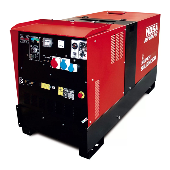
DSP 600 PS
• Motosaldatrice
• Schweißaggregat
• Engine Driven Welder
• Motosoldadora
• Motosoudeuse
• По Вышкам
• Motosoldadoras
M A D E
I N
I T A L Y
language
Codice
Code
Code
886119003
Codigo
Kodezahl
Código
Код
Edizione
Edition
Édition
Edición
06.2016
Ausgabe
Edição
Издание
Advertisement
Table of Contents

Subscribe to Our Youtube Channel
Related Manuals for Mosa DSP 600 PS


Summary of Contents for Mosa DSP 600 PS
- Page 1 USE AND MAINTENANCE MANUAL TRANSLATION OF THE ORIGINAL INSTRUCTIONS – ENGLISH Codice DSP 600 PS Code Code 886119003 Codigo Kodezahl Código Код Edizione Edition Édition • Motosaldatrice • Schweißaggregat Edición 06.2016 • Engine Driven Welder • Motosoldadora Ausgabe • Motosoudeuse •...
-
Page 3: Front Panel
DESCRIPTION OF THE MACHINE REV.0-11/08 Main characteristics of the unit: • Control of current with CHOPPER technology at high frequency • Digital control technique by means of DSP • Major productivity of 15% in comparison to welders with diode controls and controlled diodes. •... - Page 4 INDEX REV.1-01/13 M 01 QUALITY SYSTEM M 1.1 NOTES M 1.4 CE MARK M 1.5 TECHNICAL DATA M 1.6 TECHNICAL DATA ADVICE M 2.1 SYMBOLS AND SAFETY PRECAUTIONS M 2.3 -…. ABBREVIATIONS LEGEND M 2.5.1 INSTALLATION AND ADVICE BEFORE USE M 2.6 INSTALLATION AND ADVICE M 2.7...
- Page 5 (see page M1.1). All rights are reserved to said Company. It is a property logo of MOSA division of B.C.S. S.p.A. All other possible logos contained in the documen- tation are registered by the respective owners.
-
Page 6: Notes About The Manual
Notes REV.1-03/14 INFORMATION INFORMATION OF GENERAL TYPE In the envelope given together with the machine and/or Dear Customer, set you will find: the manual for Use Maintenance and We wish to thank you for having bought a high quality set. Spare Parts, the manual for use of the engine and the tools (if included in the equipment), the guarantee (in the Our sections for Technical Service and Spare Parts will... - Page 7 CE MARKING REV.7-02/14 Any of our product is labelled with CE marking attesting its conformity to appliable directives and also the fulfillment of safety requirements of the product itself; the list of these directives is part of the declaration of conformity included in any machine standard equipment. Here below the adopted symbol: CE marking is clearly readable and unerasable and it can be either part of the data-plate.
-
Page 8: Technical Data
TECHNICAL DATA REV.3-01/13 Technical data DSP 600 PS ALTERNATOR Self-excited, self-regulated, brushless Type three-phase, asynchronous Insulating class GENERATOR Output three-phase 30 kVA / 400 V / 57.8 A Output single-phase 15 kVA / 230 V / 65.2 A Output single-phase 8 kVA / 110 V / 72.7 A... - Page 9 DSP 600 PS/PSX TECHNICAL DATA REV.2-01/13 C.C. WELDING Current Range 10 - 600A Welding current 600A - 35%, 550 A - 60%, 500A - 100% Starting voltage C.V. WELDING Welding current 550 A - 60%, 500A - 100% Welding voltage...
- Page 10 WARNINGS REV.1-02/14 The installation and general warnings regarding operations are aimed achieving correct use of the machine and/or apparatus in the place where it is used as a genset and/or motor welder. - Advice to the User about the safety: + NB: The information contained in the manual can be changed without notice.
- Page 11 SYMBOLS AND SAFETY PRECAUTIONS REV.2-06/10 SYMBOLS PROHIBITIONS No harm for persons Use only with safety clothing - STOP - Read absolutely and be duly attentive It is compulsory to use the personal protection means given in equip- ment. Use only with safety clothing - Read and pay due attention It is compulsory to use the personal protection means given in equipment.
- Page 12 PRECAUTION (ENGINE DRIVEN WELDER) 2-5- REV.0-03/00 INSTALLATION AND ADVICE BEFORE USE The operator of the welder is responsible for the security of the people who work with the welder and for those in the vicinity. The security measures must satisfy the rules and regulations for engine driven welders. The information given below is in addition to the local security norms.
-
Page 13: Gasoline Engines
INSTALLATION AND ADVICE REV.1-06/07 Check that the air gets changed completely and the hot INSTALLATION AND ADVICE BEFORE USE air sent out does not come back inside the set so as to cause a dangerous increase of the temperature. GASOLINE ENGINES Use in open space, air swept or vent exhaust gases, which contain the deathly carbone oxyde, far from the work area. - Page 14 Installazione Luftzirkulation Installation Instalación GE 35 PSX Installation DSP 600 PSX REV.1-05/08 M1.4 M1.4...
- Page 15 Dimensioni Abmessungen Dimensions Dimensiones GE 35 PSX - 55 PS 2.7.1 Dimensions DSP 600 PSX REV.1-05/08 ø13 n° 4 for i 1640 2030 ø13 57. 5...
- Page 16 UNPACKING REV.1-02/04 NOTE + Be sure that the lifting devices are: correctly mounted, adequate for the weight of the machine with it’s pack- aging, and conforms to local rules and regulations. When receiving the goods make sure that the product has not suffered damage during the transport, that there has not been rough handling or taking away of parts contained inside the packing or in the set.
- Page 17 TRANSPORT AND DISPLACEMENTS COVERED UNITS REV.1-06/10 NOTE Transportation must always take place with the engine off, electrical cables and starting battery disconnected and fuel tank empty. Be sure that the lifting devices are: correctly mounted, adequate for the weight of the machine with it’s packaging, and conform to local rules and regulations.
- Page 18 CTL 35 - 45 - 50 - 95 ASSEMBLY REV.1-03/06 ATTENTION The CTL accessory cannot be removed from the machine and used separately (actioned manually or following vehicles) for the transport of loads or anyway for used different from the machine movements. TRAILERS The machines provided for assembling the CTL accessory (slow towing trolley) can be towed up to a maximum speed of 40 Kms/hour on asphalted surfaces.
-
Page 19: Air Filter
Set-up for operation Water cooled systems REV.2-04/15 AIR FILTER BATTERY WITHOUT MAINTENANCE The starter battery is supplied Check that the dry air filter is correctly installed and already charged and ready for that there are no leaks around the filter which could use. -
Page 20: Cooling Liquid
Set-up for operation Water cooled systems REV.2-04/15 ELECTRICAL CONNECTIONs COOLING LIQUID ATTENTION ATTENTION A qualified electrician should carry out electrical con- nections according to the norms in force. Do not remove the radiator tap with the motor in operation or still hot, as the liquid coolant may spurt out and cause serious burns. -
Page 21: Starting The Engine
STARTING THE ENGINE REV.0-02/13 Check daily 4. The engine starts up at its operating speed, 1500 or 1800 rpm. After start-up, allow the engine to run for a few minutes before powering on the utilities. See table; Temperature Time NOTE ≤... -
Page 22: Emergency Shutdown
STOPPING THE ENGINE REV.0-02/13 STOP For shutdown under normal conditions, proceed as follows: 1. Break the welding process in course 2. Break the production of a.c. auxiliary generation dividing the loads or opening the electri- cal protection interrupter. 3. Let the engine run with no load for a few minutes. 4. -
Page 23: Specification
PROTECTIONS EP7 ENGINE PROTECTION 39.13 REV.0-10/07 Description Specification The EP7 includes the basic safeguards to protect an DC Supply, Battery Plant 8V up to 36 Vdc Static Outputs (short circuit proof) 200 mAdc DIESEL engine. The EP7 features 7 LEDs, 3 Static Key Switch Rating 30 A (30 secs)/80 A (5 secs) Outputs and a 30A Key Switch. - Page 24 CONTROLS LEGENDE REV.3-04/13 Hydraulic oil level light Exclusion indicating light PTO HI Selection push button 30 l/1' PTO HI Welding socket ( + ) Auxiliary current push button Battery voltmeter Welding socket ( - ) Fuel level light Remote control socket Earth terminal E.A.S. PCB Button indicating light 20 l/1' PTO HI A.C. socket Control unit for generating sets QEA Commutator/switch, serial/parallel Accelerator lever Thermal-magnetic circuit breaker Ground fault interrupter ( 30 mA ) Feed pump Selection push button 20 l/1' PTO HI Engine control unit and economiser 48V D.C. socket Water temperature indicator Engine air filter Ammeter Oil level dipstick Frequency meter Engine oil reservoir cap Frequency rpm regulator 24A Hydraulic oil reservoir cap Voltmeter regulator 24B Water filling cap Fuse Fuel prefilter Stop switch Fuel tank cap Warning light, high temperature Muffler...
- Page 25 Bedienelemente Comandi Controls Commandes REV.2-11/08...
-
Page 26: Welding Cable Connection
USE AS A WELDER REV.1-03/02 ATTENTION Access to non qualified personnel is prohibited in proximity of these areas: - the control panel (front-end) - the engine exhaust fumes - the welding process. This symbol (regulation EN 60974-1 on safety requirements for arc welding apparatus) indi- cates that the engine driven welder is suitable for use in environments with an increased risk of electrical shock. -
Page 27: Getting Started
WELDING DIGITAL CONTROL REV.1-01/08 WELDING DIGITAL CONTROL CC-STICK ARC FORCE CELLULOSE 1 CELLULOSE 2 CONTACT STARTING CV-WIRE STAND-BY 400A RANGE POLARITY CURRENT CC INVERTER REMOTE CONTROL GETTING STARTED SETTING THE WELDING PROCESS 1) After having prepared the machine (charged the battery, put in oil and fuel) the machine is ready for operation. Before starting the engine please note the following: - The welder should only be operated by qualified personnel with experience in working with engine driven welders. - Check the oil level daily. Fuel should be put in before starting the engine. -
Page 28: Tig Mode
WELDING DIGITAL CONTROL REV.2-11/12 TIG MODE 1) “ON” LED blinking Contact starting TIG When the engine of the welder is started the control unit automatically This position is specifically for TIG welding. To cre- goes to the stand by mode for few ate the arc simply place the tip of the TIG electrode istants (stand-by LED on) and performs a self-dia- on the piece that requires welding then gently move gnosis of the current sensor connector and power the tip away. The arc starts automatically and at the source voltage + 15V; then the selected process is same time the welding current rises to the preset loaded (on led turned ON). value, using the welding current adjustment knob In case of malfunction the “ON” LED blinks. which is on the lower part of the control panel. The welding current can be adjusted continuously 2) Red LED blinking from a minimum of 10 A to a maximum which depen- The chopper has a thermal protection, ds on the power of the machine 400 A, 500 A, 600 A. - Page 29 WELDING DIGITAL CONTROL REV.1-01/08 WIRE FEEDER CONNECTED WITH REMOTE WARNING CONTROL CONNECTOR You can use the wire feeder only by respecting Wire feeder connection the pin configuration as shown on the below Connect the wire feeder to the welder with the wel- mentioned table.
-
Page 30: Accessory Use
REMOTE CONTROL ACCESSORY USE RC1 (PL Version) 38.9 RC1/90° (PL Version) REV.2-09/10 PUSH AND SCREW TIGHT PUSH AND SCREW TIGHT The remote control RC, which regulates the welding current in the CC (STICK welding) mode and the welding voltage in the CV (MIG/MAG welding), is connected to the front panel by means of a multipole connector. - Page 31 REMOTE CONTROL ACCESSORY USE (DSP/CS SERIES) 38.10 RC2/90° REV.3-12/11 PUSH AND SCREW TIGHT PUSH AND SCREW TIGHT The remote control RC, which regulates the welding current in the CC (STICK welding) mode and the welding voltage in the CV (MIG/MAG welding), is connected to the front panel by means of a multipole connector.
-
Page 32: Thermal Protection
WELDING DIGITAL CONTROL USE AS A GENERATOR REV.1-06/10 minutes to allow the thermal WARNING protection to cool down. PUSH TO Before resetting by pressing It is strictly forbidden to connect the group to RESET the central button and then the public mains and/or to any other source connect the load again. -
Page 33: Troubleshooting
TROUBLE SHOOTING DSP - EP5/EP7/ES 40.1 REV.0-05/05 PROBLEM POSSIBLE CAUSE WHAT TO DO WELDING P1 All functions performed by 1) Position of regulation poten- 1) Adjust the position of the WDC regulation knob on the potentiometer the WDC are regular, but tiometer incorrect knob spindle so that the potentiometer is not completely at the end of its travel there is no tension on the when the knob reaches its minimum position. - Page 34 TROUBLE SHOOTING DSP - EP5/EP7/ES 40.2 REV.3-09/07 PROBLEM POSSIBLE CAUSE WHAT TO DO WELDING WITH V.R.D. P10 The welding tension after 1) Net R.C. defective or disconnected 1) Check the net R.C. Check the connections. 3 sec isn’t less enough from + or - welding socket (plus in 12V dc) 2) WDC defective.
- Page 35 TROUBLE SHOOTING DSP - EP5/EP7/ES 40.3 REV.1-02/11 CHOPPER TEST CHECK THE FOLLOWING RESISTIVE VALUES ON THE CHOPPER CONNECTOR OUTPUT 18 Vca 10 Vca OUTPUT 18 Vca OUTPUT OUTPUT 25 Vca WIEW FROM INSERTION SIDE Check the resistive values between the following pairs of pins, by means of an ohmmeter.
- Page 36 TROUBLE SHOOTING DSP - EP5/EP7/ES 40.4 REV.0-05/05 Put the knob on RC1 at minimum/max, put one ohmmeter from pin A - B and measure the resistance. Knob Resistance Minimum 50 ÷ 100 Ω 4,5 - 4,7 KΩ DRAWING 4 P1 Supply connector P2 Chopper connector P3 Current sensor connector P4 - P5 Free DRAWING 5...
- Page 37 MAINTENANCE REV.1-01/13 WARNING ● Have qualified personnel do maintenance and troubleshooting work. ● Stop the engine before doing any work inside the machine. If for any reason the machine must be operated while working inside, pay at- tention moving parts, hot parts (exhaust manifold and muffler, etc.) electrical parts which may be unprotected when the machine is open.
-
Page 38: Gasoline Engine
STORAGE REV.0-06/07 In case the machine should not be used for more than 30 days, make sure that the room in which it is stored presents a suitable shelter from heat sources, weather changes or anything which can cause rust, corrosion or damages to the machine. - Page 39 CUST OFF REV.0-06/07 Have qualified personnel disassemble the In case of necessity for first aid and fire prevention, machine and dispose of the parts, including the see page M2.5. oil, fuel, etc., in a correct manner when it is to be taken out of service.
- Page 40 RECOMMENDED ELECTRODES (In accordance with A.W.S Standard) REV.0-10/03 The information here below are to be intended only as indicative since the above norm is much larger. For further details please see the specific norms and/or the manufacturers of the product to be used in the welding process.
- Page 41 ELECTRICAL SYSTEM LEGENDE REV.11-06/14 A : Alternator E3 : Open circuit voltage switch I6 : Start Local/Remote selector N9 : UP/DOWN button mast B : Wire connection unit F3 : Stop push-button L6 : Choke button O9 : Hydraulic unit solenoid valve C : Capacitor G3 : Ignition coil M6 : Switch CC/CV P9 : Hydraulic unit engine D : G.F.I. H3 : Spark plug N6 : Connector – wire feeder Q9 : Ignitor E : Welding PCB transformer I3 : Range switch O6 : 420V/110V 3-phase transformer...
- Page 42 Schema elettrico Stromlaufplan 61.1 Electric diagram REV.3-01/13...
- Page 43 Schema elettrico Stromlaufplan 400T230M110Mx2 61.2 Electric diagram REV.1-11/08...
- Page 44 Schema elettrico Stromlaufplan 400T230Mx3 61.3 Electric diagram REV.1-11/08...
- Page 45 Schema elettrico Stromlaufplan 400T230Mx2 48M 61.4 Electric diagram REV.1-11/08...
- Page 46 Schema elettrico Stromlaufplan DSP 500/600 PS/PSX 61.5 Electric diagram REV.2-01/13...
- Page 47 Schema elettrico Stromlaufplan PL VERSION 61.6 Electric diagram REV.2-01/13...
- Page 48 Schema elettrico Stromlaufplan DSP 500-600 PS/PSX 61.7 Electric diagram REV.2-01/13...
- Page 50 MOSA div. della BCS S.p.A. Viale Europa, 59 20090 Cusago (Milano) Italy Tel.+39 - 0290352.1 Fax +39 - 0290390466 www.mosa.it...
Need help?
Do you have a question about the DSP 600 PS and is the answer not in the manual?
Questions and answers