
Subscribe to Our Youtube Channel
Related Manuals for Mosa DSP 400 YSX


Summary of Contents for Mosa DSP 400 YSX
- Page 1 DSP 400 YSX 0 3 0 9 894109003 - GB USE AND MAINTENANCE MANUAL 25/03/09 89410M00 preparato da UPT approvato da DITE...
-
Page 2: Emergency Stop
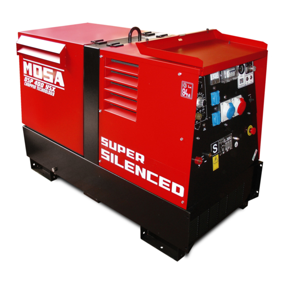
EMERGENCY STOP The DSP 400 YSX engine driven welder has a base constructed in steel which includes the tank. A cover (bonnet) which is hinged to the roll bar facilitates rapid checks for daily maintenance. A central hook on the roll bar facilitates the removal or loading of the machine. - Page 3 REV.3-02/09 UNI EN ISO 9001 : 2000 The advantages for MOSA clients are: MOSA has certified its quality system according to UNI EN ISO 9001:2000 to ensure a constant, high · Constant quality of products and services at the quality of its products. This certification covers the high level which the client expects;...
- Page 4 Index DSP 400 YSX © MOSA REV.0-03/09 M 1.01 COPYRIGHT M 1.1 NOTES M 1.4 CE MARK M 1.5 TECHNICAL DATA M 1.6 TECHNICAL DATA ENGINE DRIVEN WELDER SYMBOLS AND SAFETY PRECAUTIONS M 2.1 SYMBOLS AND SAFETY PRECAUTIONS M 2.5 -…. INSTALLATION AND ADVICE BEFORE USE M 2.6...
- Page 5 We advise you to pay attention to the pages concerning the security (see page M1.1). All rights are reserved to said Company. © It is a property logo of MOSA division of B.C.S. S.p.A. All other possible logos contained in the documentation are registered by the respective owners.
-
Page 6: Notes About The Manual
(fastenings, holes, electric or mechanical devices, incorrect maintenance. The manual is for qualified others..) if not duly authorized in writing by MOSA: personnel, who knows the rules: about safety and the responsibility coming from any potential... - Page 7 CE MARK © MOSA REV.4-10/07 Any of our product is labelled with CE marking attesting its conformity to appliable directives and also the fulfillment of safety requirements of the product itself; the list of these directives is part of the declaration of conformity included in any machine standard equipment.
- Page 8 DSP 400 YSX Technical data © MOSA REV.0-03/09 The DSP 400 engine driven welder ia a unit which ensures the function as: a) a current source for arc welding b) a current source for the auxiliary power generation It is meant for industrial and professional use, powered by an endothermic engine; it is composed of various main parts such as: engine, alternator, electric and electronic controls, the fairing or a protective structure.
- Page 9 DSP 400 YSX Technical data © MOSA REV.0-03/09 C.C. WELDING Welding current 400A/35% - 350A/60% - 300A/100% Starting voltage C.V. WELDING Welding current 350A/60% - 300A/100% Welding voltage 15 - 40V OUTPUT CARACTERISTIC SIMULTANEOUS UTILIZATION FACTORS In case Welding and Generation can be used simultaneously, however, the engine cannot be overloaded. The ta-...
-
Page 10: Symbols In This Manual
SYMBOLS AND SAFETY PRECAUTIONS GE_, MS_, TS_ © MOSA 1.0-11/99 SYMBOLS IN THIS MANUAL SAFETY PRECAUTIONS The symbols used in this manual are designed to call DANGEROUS your attention to important aspects of the operation of the machine as well as potential hazards and dangers This heading warns of an immediate danger for persons for persons and things. -
Page 11: Symbols And Safety Precautions
GE_, MS_, TS_ © MOSA 1.1-04/03 SYMBOLS PROHIBITIONS (for all MOSA models) No harm for persons Use only with safety clothing - STOP - Read absolutely and be duly attentive It is compulsory to use the personal protection means given in equipment. - Page 12 INSTALLATION AND ADVICE BEFORE USE GE_, MS_, TS_ © MOSA 1.0-06/00 The installation and the general advice concerning the operations, are finalized to the correct use of the machine, in the place where it is used as generator group and/or welder.
- Page 13 PRECAUTION (ENGINE DRIVEN WELDER) GE_, MS_, TS_ 2-5- © MOSA 1.0-03/00 INSTALLATION AND ADVICE BEFORE USE The operator of the welder is responsible for the security of the people who work with the welder and for those in the vicinity.
-
Page 14: Gasoline Engines
INSTALLATION AND ADVICE © MOSA REV.1-06/07 INSTALLATION AND ADVICE BEFORE USE Check that the air gets changed completely and the hot air sent out does not come back inside the set so as to cause a dangerous increase of the temperature. - Page 15 Installazione Luftzirkulation Installation DSP 400 YSX © MOSA REV.0-12/07 Installation M1.4 M1.4 A...
- Page 16 UNPACKING GE_, MS_, TS_ © MOSA 1.1-02/04 NOTE ☞ Be sure that the lifting devices are: correctly mounted, adequate for the weight of the machine with it’s packaging, and conforms to local rules and regula- tions. When receiving the goods make sure that the prod-...
- Page 17 TRANSPORT AND DISPLACEMENTS COVERED UNITS GE_, MS_, TS_ © MOSA 1.0-03/00 NOTE In case you should transport or move the machine, keep to the instructions as per the figures. Make the transportation when the machine has no petrol in its tank, no oil in the engine and and electrolyte in the battery.
- Page 18 CTL400 ASSEMBLY © MOSA 1.0-03/00 ATTENTION The CTL accessory cannot be removed from the machine and used separately (actioned manually or following vehicles) for the transport of loads or anyway for used different from the machine movements. Nota : Lift the machine and assemble the parts as shown in the drawing...
-
Page 19: Air Filter
RECOMMENDED OIL Avoid accidentally spilling fuel. Clean MOSA recommends selecting AGIP engine oil. any eventual leaks before starting up Refer to the label on the motor for the recommended motor. products. -
Page 20: Cooling Liquid
Set-up for operation TS_,DSP_,GE Water cooled systems © MOSA 1.0-06/03 COOLING LIQUID ATTENTION Do not remove the radiator tap with the motor in operation or still hot, as the liquid coolant may spurt out and cause serious burns. Remove the tap very carefully. -
Page 21: Starting The Engine
STARTING THE ENGINE DSP 400 YSX © MOSA REV.0-03/09 4. the motor starts up at its operating speed, 1500 Check daily or 1800 rpm. After start-up, allow the motor to run for a few minutes before powering on the utilities. -
Page 22: Stopping The Engine
STOPPING THE ENGINE DSP 400 YSX © MOSA REV.0-03/09 STOP For shutdown under normal conditions, proceed as follows: 1. Break the welding process in course 2. Break the production of a.c. auxiliary generation dividing the loads or opening the GFI (D). - Page 23 Comandi Bedienelemente Controls DSP 400 YSX Commandes © MOSA REV.0-12/07 4 0 0 Y 2 3 0 I x 3 V e r s i o 4 0 0 Y 2 (Isometer version) 3 0 I 4 8 I V e r s i o...
-
Page 24: Welding Cable Connection
USE AS A WELDER © MOSA 1.0-04/02 ATTENTION Access to non qualified personnel is prohibited in proximity of these areas: - the control panel (front-end) - the engine exhaust fumes - the welding process. This symbol (regulation EN 60974-1 on safety... -
Page 25: Getting Started
WELDING DIGITAL CONTROL © MOSA REV.1-01/08 WELDING DIGITAL CONTROL CC-STICK ARC FORCE CELLULOSE 1 CELLULOSE 2 CONTACT STARTING CV-WIRE STAND-BY 400A RANGE POLARITY CURRENT CC INVERTER REMOTE CONTROL GETTING STARTED SETTING THE WELDING PROCESS 1) After having prepared the machine (charged the battery, put in oil and fuel) the machine is ready for operation. -
Page 26: Tig Mode
WELDING DIGITAL CONTROL © MOSA REV.1-01/08 TIG MODE Inversion of polarity (Optional, available on Contact starting TIG request) This position is specifically for TIG welding. To cre- In order to invert polarity, press the switch on the ate the arc simply place the tip of the TIG electrode remote control unit. - Page 27 WELDING DIGITAL CONTROL © MOSA REV.1-01/08 WIRE FEEDER CONNECTED WITH REMOTE WARNING CONTROL CONNECTOR You can use the wire feeder only by respecting Wire feeder connection the pin configuration as shown on the below Connect the wire feeder to the welder with the mentioned table.
-
Page 28: Thermal Protection
WELDING DIGITAL CONTROL USE AS A GENERATOR © MOSA 1.0-04/02 Before resetting by pressing WARNING the central button and then PUSH TO connect the load again. It is strictly forbidden to connect the group to RESET If the protection should... - Page 29 38.9 RC1 REMOTE CONTROL © MOSA 1.0-04/02 PUSH AND SCREW TIGHT Is it possible to connect the RC1, to all DSP engine driven welders. The remote control RC1, which regulates the welding current in the CC mode and the welding voltage in the CV mode, is connected to the front panel by means of a multipole connector.
-
Page 30: Specification
PROTECTIONS EP7 ENGINE PROTECTION 39.13 © MOSA REV.0-10/07 Description Specification The EP7 includes the basic safeguards to protect DC Supply, Battery Plant 8V up to 36 Vdc Static Outputs (short circuit proof) 200 mAdc an DIESEL engine. The EP7 features 7 LEDs, 3... -
Page 31: Troubleshooting
TROUBLE SHOOTING DSP - EP5/EP7/ES 40.1 © MOSA REV.0-05/05 PROBLEM POSSIBLE CAUSE WHAT TO DO WELDING P1 All functions performed 1) Position of regulation poten- 1) Adjust the position of the WDC regulation knob on the by the WDC are regular,... - Page 32 TROUBLE SHOOTING DSP - EP5/EP7/ES 40.2 © MOSA REV.3-09/07 POSSIBLE CAUSE WHAT TO DO PROBLEMS generation unless the output going to the condensers) and check the capacity of the condensers. Restart the machine, if there is still no output, replace the alternator.
- Page 33 TROUBLE SHOOTING DSP - EP5/EP7/ES 40.3 © MOSA REV.0-05/05 CHECK THE CHOPPER FROM THE CONNECTOR CHOPPER CONNECTOR CHECK MOSFET ON CHOPPER OUTPUT 18 Vca 10 Vca OUTPUT 18 Vca OUTPUT OUTPUT 25 Vca FOR THE CHECK HOLD THE CONNECTOR AS SHOWED ABOVE...
- Page 34 TROUBLE SHOOTING DSP - EP5/EP7/ES 40.4 © MOSA REV.0-05/05 Put the knob on RC1 at minimum/max, put one ohmmeter from pin A - B and measure the resistance. Knob Resistance 50 ÷ 100 Ω Minimum 4,5 - 4,7 KΩ DRAWING 4...
-
Page 35: Engine And Alternator
MAINTENANCE © MOSA 1.0-09/05 WARNING Have qualified personnel do maintenance and troubleshooting work. ● Stop the engine before doing any work inside the machine. If for any ● reason the machine must be operated while working inside, pay attention moving parts, hot parts (exhaust manifold and muffler, etc.) electrical parts which may be unprotected when the machine... -
Page 36: Gasoline Engine
STORAGE GE_, MS_, TS_ © MOSA 1.0-06/00 In case the machine should not be used for more than 30 days, make sure that the room in which it is stored presents a suitable shelter from heat sources, weather changes or anything which can cause rust, corrosion or damages to the machine. - Page 37 - tank fuel - engine lubricating oil - cooling liquid from the engine - battery NOTE: MOSA is involved with custing off the machine only for the second hand ones, when not reparable. This, of course, after authorization.
- Page 38 MS_, TS_ RECOMMENDED ELECTRODES (In accordance with A.W.S Standard) © MOSA 1.0-10/03 The information here below are to be intended only as indicative since the above norm is much larger. For further details please see the specific norms and/or the manufacturers of the product to be used in the welding process.
- Page 39 Dimensioni Abmessungen Dimensions DSP 400 YSX © MOSA REV.0-12/07 Installation Ø13 1190 1610 Ø13 32.5...
- Page 40 ELECTRICAL SYSTEM LEGENDE GE_, MS_, TS_ © MOSA REV.6-06/08 Alternator A3: Insulation moitoring A6: Commutator/switch Wire connection unit B3: E.A.S. connector B6: Key switch, on/off Capacitor C3: E.A.S. PCB C6: QEA control unit G.F.I. D3: Booster socket D6: Connector, PAC...
- Page 41 Schema elettrico Stromlaufplan DSP 400 YSX 61.1 Electric diagram © MOSA REV.0-12/07 RED/WHITE YELLOW BLACK...
- Page 42 Schema elettrico Stromlaufplan DSP 400 YSX 61.2 Electric diagram 400Y230Ix3 © MOSA REV.0-12/07...
- Page 43 Schema elettrico Stromlaufplan DSP 400 YSX 61.3 Electric diagram AU Version © MOSA REV.0-12/07...
- Page 44 Schema elettrico Stromlaufplan DSP 400 YSX 61.4 Electric diagram 400Y230I48I © MOSA REV.0-12/07...
- Page 45 Schema elettrico Stromlaufplan DSP 400 YSX 61.5 Electric diagram © MOSA REV.0-12/07...
- Page 46 Schema elettrico Stromlaufplan DSP 400 YSX 61.6 Electric diagram 400Y230Ix3 PL version © MOSA REV.0-12/07...
- Page 47 Schema elettrico Stromlaufplan DSP 400 YSX 61.7 Electric diagram AU Version © MOSA REV.0-12/07...
- Page 48 Schema elettrico Stromlaufplan DSP 400 YSX 61.8 Electric diagram 400Y230Ix3 / 400Y230I48I © MOSA REV.0-12/07...
- Page 49 Schema elettrico Stromlaufplan DSP 400 YSX 61.9 Electric diagram PL / AU version © MOSA REV.0-12/07...
Need help?
Do you have a question about the DSP 400 YSX and is the answer not in the manual?
Questions and answers