
Related Manuals for Mosa DSP 600 PSX


Summary of Contents for Mosa DSP 600 PSX
- Page 1 DSP 600 PS/PSX 0 1 1 3 886119003 - GB USE AND MAINTENANCE MANUAL SPARE PARTS CATALOG © MOSA 12/05/06 88611M00 preparato da UPT approvato da DITE...
-
Page 3: Front Panel
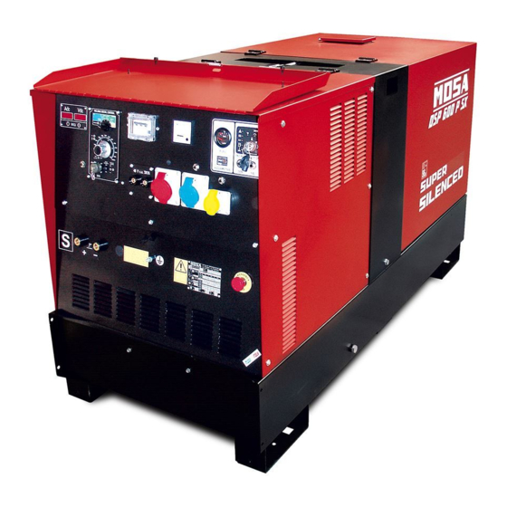
DESCRIPTION OF THE MACHINE DSP 600 PS/PSX REV.0-11/08 Main characteristics of the unit: • Control of current with CHOPPER technology at high frequency • Digital control technique by means of DSP • Major productivity of 15% in comparison to welders with diode controls and controlled diodes. • 5 Welding processes: TIG contact start, STICK arcforce 1, STICK arcforce 2, STICK arcforce 3, MIG-MAG • Maximum welding current 600A • Voltmeter and Ammeter of weld • 30 kVA of power in three phase generation 400 V / 50 Hz • Perkins diesel engine 1103C - 33G3 emissioned EURO 2 • Noise level at 7m 69 dBA • Dimensions / weight: 2050x870x1135 / 990 Kg (PS) - 1000 Kg (PSX). LIFTING ROLL-BAR CANOPY FILTER BATTERY BASE/ TANK ENGINE WELDING CONTROL... - Page 5 · Competent support in the solution of problems; ofthe International Certification Network IQNet, · Information and training in the correct applicatio- awarded the official approval to MOSA after an- nand use of the products to assure the security examination of its operations at the head office ofthe operator and protect the environment;...
- Page 6 INDEX DSP 600 PS/PSX REV.1-01/13 M 01 QUALITY SYSTEM M 1.01 COPYRIGHT M 1.1 NOTES M 1.4 CE MARK M 1.4.1 DECLARATION OF CONFORMITY M 1.5 TECHNICAL DATA M 1.6 TECHNICAL DATA M 2 ..SYMBOLS AND SAFETY PRECAUTIONS M 2.3 -…. ABBREVIATIONS LEGEND M 2.5 -…. INSTALLATION AND ADVICE BEFORE USE M 2.6 INSTALLATION AND ADVICE M 2.7 INSTALLATION M 2.7.1 DIMENSIONS M 3 UNPACKING M 4 TRANSPORT AND DISPLACEMENTS COVERED UNITS M 6.8 ASSEMBLY CTL M 20..PREPARING THE UNIT M 21 START-UP M 22 SHUTTING DOWN THE MOTOR...
- Page 7 (see page M1.1). All rights are reserved to said Company. It is a property logo of MOSA division of B.C.S. S.p.A. All other possible logos contained in the documen- tation are registered by the respective owners.
-
Page 8: Notes About The Manual
Notes REV.0-10/02 INFORMATION INFORMATION OF GENERAL TYPE In the envelope given together with the machine and/or Dear Customer, set you will find: the manual for Use Maintenance and We wish to thank you for having bought a high quality set. Spare Parts, the manual for use of the engine and the tools (if included in the equipment), the guarantee (in the Our sections for Technical Service and Spare Parts will... - Page 9 CE MARK REV.5-03/11 Any of our product is labelled with CE marking attesting its conformity to appliable directives and also the fulfillment of safety requirements of the product itself; the list of these directives is part of the declaration of conformity included in any machine standard equipment. Here below the adopted symbol: CE marking is clearly readable and unerasable and it can be either part of the data-plate.
-
Page 10: Dichiarazione Di Conformita
BCS S.p.A. declara bajo su responsabilidad que la máquina: GRUPPO ELETTROGENO DI SALDATURA / WELDING GENERATOR GRUPPO ELETTROGENO / POWER GENERATOR Marchio / Brand : MOSA Modello / Model : Matricola / Serial number: è conforme con quanto previsto dalle Direttive Comunitarie e relative modifiche: est en conformité... -
Page 11: Technical Data
DSP 600 PS/PSX TECHNICAL DATA REV.3-01/13 Technical data DSP 600 PS DSP 600 PSX ALTERNATOR Self-excited, self-regulated, brushless Type three-phase, asynchronous Insulating class GENERATOR Output three-phase 30 kVA / 400 V / 57.8 A Output single-phase 15 kVA / 230 V / 65.2 A Output single-phase 8 kVA / 110 V / 72.7 A... - Page 12 DSP 600 PS/PSX TECHNICAL DATA REV.2-01/13 C.C. WELDING Current Range 10 - 600A Welding current 600A - 35%, 550 A - 60%, 500A - 100% Starting voltage C.V. WELDING Welding current 550 A - 60%, 500A - 100% Welding voltage 16 - 40V STATIC CHARACTERISTIC SIMULTANEOUS UTILIZATION FACTORS...
-
Page 13: Symbols In This Manual
SYMBOLS AND SAFETY PRECAUTIONS REV.0-11/99 SYMBOLS IN THIS MANUAL SAFETY PRECAUTIONS DANGEROUS The symbols used in this manual are designed to call your attention to important aspects of the operation of the machine as well as potential hazards and dangers This heading warns of an immediate danger for persons for persons and things. -
Page 14: Symbols And Safety Precautions
SYMBOLS AND SAFETY PRECAUTIONS REV.2-06/10 SYMBOLS PROHIBITIONS No harm for persons Use only with safety clothing - STOP - Read absolutely and be duly attentive It is compulsory to use the personal protection means given in equip- ment. Use only with safety clothing - Read and pay due attention It is compulsory to use the personal protection means given in equipment. - Page 15 INSTALLATION AND ADVICE BEFORE USE REV.0-06/00 The installation and the general advice concerning the operations, are finalized to the correct use of the ma- chine, in the place where it is used as generator group and/or welder. Stop engine when fueling Do not touch electric devices if you are barefoot or with wet Do not smoke, avoid flames, sparks or electric tools when fueling.
- Page 16 PRECAUTION (ENGINE DRIVEN WELDER) 2-5- REV.0-03/00 INSTALLATION AND ADVICE BEFORE USE The operator of the welder is responsible for the security of the people who work with the welder and for those in the vicinity. The security measures must satisfy the rules and regulations for engine driven welders. The information given below is in addition to the local security norms.
-
Page 17: Gasoline Engines
INSTALLATION AND ADVICE REV.1-06/07 Check that the air gets changed completely and the hot INSTALLATION AND ADVICE BEFORE USE air sent out does not come back inside the set so as to cause a dangerous increase of the temperature. GASOLINE ENGINES Use in open space, air swept or vent exhaust gases, which contain the deathly carbone oxyde, far from the work area. - Page 18 Installazione Luftzirkulation Installation Instalación GE 35 PSX Installation DSP 600 PSX REV.1-05/08 M1.4 M1.4...
- Page 19 Dimensioni Abmessungen Dimensions Dimensiones GE 35 PSX - 55 PS 2.7.1 Dimensions DSP 600 PSX REV.1-05/08 ø13 n° 4 for i 1640 2030 ø13 57. 5...
- Page 20 UNPACKING REV.1-02/04 NOTE + Be sure that the lifting devices are: correctly mounted, adequate for the weight of the machine with it’s pack- aging, and conforms to local rules and regulations. When receiving the goods make sure that the product has not suffered damage during the transport, that there has not been rough handling or taking away of parts contained inside the packing or in the set.
- Page 21 TRANSPORT AND DISPLACEMENTS COVERED UNITS REV.1-06/10 NOTE Transportation must always take place with the engine off, electrical cables and starting battery disconnected and fuel tank empty. Be sure that the lifting devices are: correctly mounted, adequate for the weight of the machine with it’s packaging, and conform to local rules and regulations.
- Page 22 CTL 35 - 45 - 50 - 95 ASSEMBLY REV.1-03/06 ATTENTION The CTL accessory cannot be removed from the machine and used separately (actioned manually or following vehicles) for the transport of loads or anyway for used different from the machine movements. TRAILERS The machines provided for assembling the CTL accessory (slow towing trolley) can be towed up to a maximum speed of 40 Kms/hour on asphalted surfaces.
- Page 23 Avoid accidentally spilling fuel. Clean RECOMMENDED OIL any eventual leaks before starting up MOSA recommends selecting AGIP engine oil. motor. Refer to the label on the motor for the recommended products. Refill the tank with good quality diesel fuel, such as automobile type diesel fuel, for example.
-
Page 24: Cooling Liquid
Set-up for operation Water cooled systems REV.1-02/11 GROUNDING CONNECTION COOLING LIQUID ATTENTION The grounding connection to an earthed installation is obligatory for all models equipped with a diffe- Do not remove the radiator tap with the rential switch (circuit breaker). In these groups the motor in operation or still hot, as the generator star point is generally connected to the liquid coolant may spurt out and cause... -
Page 25: Starting The Engine
STARTING THE ENGINE REV.0-02/13 Check daily 4. The engine starts up at its operating speed, 1500 or 1800 rpm. After start-up, allow the engine to run for a few minutes before powering on the utilities. See table; Temperature Time NOTE ≤... -
Page 26: Emergency Shutdown
STOPPING THE ENGINE REV.0-02/13 STOP For shutdown under normal conditions, proceed as follows: 1. Break the welding process in course 2. Break the production of a.c. auxiliary generation dividing the loads or opening the electri- cal protection interrupter. 3. Let the engine run with no load for a few minutes. 4. -
Page 27: Specification
PROTECTIONS EP7 ENGINE PROTECTION 39.13 REV.0-10/07 Description Specification The EP7 includes the basic safeguards to protect an DC Supply, Battery Plant 8V up to 36 Vdc Static Outputs (short circuit proof) 200 mAdc DIESEL engine. The EP7 features 7 LEDs, 3 Static Key Switch Rating 30 A (30 secs)/80 A (5 secs) Outputs and a 30A Key Switch. - Page 28 CONTROLS LEGENDE REV.3-04/13 Hydraulic oil level light Exclusion indicating light PTO HI Selection push button 30 l/1' PTO HI Welding socket ( + ) Auxiliary current push button Battery voltmeter Welding socket ( - ) Fuel level light Remote control socket Earth terminal E.A.S. PCB Button indicating light 20 l/1' PTO HI A.C. socket Control unit for generating sets QEA Commutator/switch, serial/parallel Accelerator lever Thermal-magnetic circuit breaker Ground fault interrupter ( 30 mA ) Feed pump Selection push button 20 l/1' PTO HI Engine control unit and economiser 48V D.C. socket Water temperature indicator Engine air filter Ammeter Oil level dipstick Frequency meter Engine oil reservoir cap Frequency rpm regulator 24A Hydraulic oil reservoir cap Voltmeter regulator 24B Water filling cap Fuse Fuel prefilter Stop switch Fuel tank cap Warning light, high temperature Muffler...
- Page 29 Bedienelemente Comandi Controls DSP 600 PS/PSX Commandes REV.2-11/08...
-
Page 30: Welding Cable Connection
USE AS A WELDER REV.1-03/02 ATTENTION Access to non qualified personnel is prohibited in proximity of these areas: - the control panel (front-end) - the engine exhaust fumes - the welding process. This symbol (regulation EN 60974-1 on safety requirements for arc welding apparatus) indi- cates that the engine driven welder is suitable for use in environments with an increased risk of electrical shock. -
Page 31: Getting Started
WELDING DIGITAL CONTROL REV.1-01/08 WELDING DIGITAL CONTROL CC-STICK ARC FORCE CELLULOSE 1 CELLULOSE 2 CONTACT STARTING CV-WIRE STAND-BY 400A RANGE POLARITY CURRENT CC INVERTER REMOTE CONTROL GETTING STARTED SETTING THE WELDING PROCESS 1) After having prepared the machine (charged the battery, put in oil and fuel) the machine is ready for operation. Before starting the engine please note the following: - The welder should only be operated by qualified personnel with experience in working with engine driven welders. - Check the oil level daily. Fuel should be put in before starting the engine. -
Page 32: Tig Mode
WELDING DIGITAL CONTROL REV.2-11/12 TIG MODE 1) “ON” LED blinking Contact starting TIG When the engine of the welder is started the control unit automatically This position is specifically for TIG welding. To cre- goes to the stand by mode for few ate the arc simply place the tip of the TIG electrode istants (stand-by LED on) and performs a self-dia- on the piece that requires welding then gently move gnosis of the current sensor connector and power the tip away. The arc starts automatically and at the source voltage + 15V; then the selected process is same time the welding current rises to the preset loaded (on led turned ON). value, using the welding current adjustment knob In case of malfunction the “ON” LED blinks. which is on the lower part of the control panel. The welding current can be adjusted continuously 2) Red LED blinking from a minimum of 10 A to a maximum which depen- The chopper has a thermal protection, ds on the power of the machine 400 A, 500 A, 600 A. - Page 33 WELDING DIGITAL CONTROL REV.1-01/08 WIRE FEEDER CONNECTED WITH REMOTE WARNING CONTROL CONNECTOR You can use the wire feeder only by respecting the Wire feeder connection pin configuration as shown on the below mentioned Connect the wire feeder to the welder with the wel- table. der turned off: -Welding cable between the machine’s (9) welding plug (+) and the wire feeder. “WIRE FEEDER connected without remote con- -Welding cable between the machine’s (10) welding trol connector” plug (-) and the piece to be welded. Welding voltage is always present on welding so- -Control/power cable between the machine’s con- ckets and also VRD is active. nector (X1) and the corresponding connector on the wire feeder. -Welding cable between the machine’s (9) welding plug (+) and the wire feeder. Start the machine welder -Welding cable between the machine’s (10) welding The “ON” LED will be off and will turn on only when plug (-) and the piece to be welded.
-
Page 34: Accessory Use
REMOTE CONTROL ACCESSORY USE RC1 (PL Version) 38.9 RC1/90° (PL Version) REV.2-09/10 PUSH AND SCREW TIGHT PUSH AND SCREW TIGHT The remote control RC, which regulates the welding current in the CC (STICK welding) mode and the welding voltage in the CV (MIG/MAG welding), is connected to the front panel by means of a multipole connector. - Page 35 REMOTE CONTROL ACCESSORY USE (DSP/CT SERIES) 38.10 RC2/90° REV.3-12/11 PUSH AND SCREW TIGHT PUSH AND SCREW TIGHT The remote control RC, which regulates the welding current in the CC (STICK welding) mode and the welding voltage in the CV (MIG/MAG welding), is connected to the front panel by means of a multipole connector.
-
Page 36: Thermal Protection
WELDING DIGITAL CONTROL USE AS A GENERATOR REV.1-06/10 minutes to allow the thermal WARNING protection to cool down. PUSH TO Before resetting by pressing It is strictly forbidden to connect the group to RESET the central button and then the public mains and/or to any other source connect the load again. -
Page 37: Troubleshooting
TROUBLE SHOOTING DSP - EP5/EP7/ES 40.1 REV.0-05/05 PROBLEM POSSIBLE CAUSE WHAT TO DO WELDING P1 All functions performed by 1) Position of regulation poten- 1) Adjust the position of the WDC regulation knob on the potentiometer the WDC are regular, but tiometer incorrect knob spindle so that the potentiometer is not completely at the end of its travel there is no tension on the when the knob reaches its minimum position. - Page 38 TROUBLE SHOOTING DSP - EP5/EP7/ES 40.2 REV.3-09/07 PROBLEM POSSIBLE CAUSE WHAT TO DO WELDING WITH V.R.D. P10 The welding tension after 1) Net R.C. defective or disconnected 1) Check the net R.C. Check the connections. 3 sec isn’t less enough from + or - welding socket (plus in 12V dc) 2) WDC defective.
- Page 39 TROUBLE SHOOTING DSP - EP5/EP7/ES 40.3 REV.1-02/11 CHOPPER TEST CHECK THE FOLLOWING RESISTIVE VALUES ON THE CHOPPER CONNECTOR OUTPUT 18 Vca 10 Vca OUTPUT 18 Vca OUTPUT OUTPUT 25 Vca WIEW FROM INSERTION SIDE Check the resistive values between the following pairs of pins, by means of an ohmmeter.
- Page 40 TROUBLE SHOOTING DSP - EP5/EP7/ES 40.4 REV.0-05/05 Put the knob on RC1 at minimum/max, put one ohmmeter from pin A - B and measure the resistance. Knob Resistance Minimum 50 ÷ 100 Ω 4,5 - 4,7 KΩ DRAWING 4 P1 Supply connector P2 Chopper connector P3 Current sensor connector P4 - P5 Free DRAWING 5...
- Page 41 MAINTENANCE REV.1-01/13 WARNING ● Have qualified personnel do maintenance and troubleshooting work. ● Stop the engine before doing any work inside the machine. If for any reason the machine must be operated while working inside, pay at- tention moving parts, hot parts (exhaust manifold and muffler, etc.) electrical parts which may be unprotected when the machine is open.
-
Page 42: Gasoline Engine
STORAGE REV.0-06/07 In case the machine should not be used for more than 30 days, make sure that the room in which it is stored presents a suitable shelter from heat sources, weather changes or anything which can cause rust, corrosion or damages to the machine. - Page 43 CUST OFF REV.0-06/07 Have qualified personnel disassemble the In case of necessity for first aid and fire prevention, machine and dispose of the parts, including the see page M2.5. oil, fuel, etc., in a correct manner when it is to be taken out of service.
-
Page 44: Recommended Electrodes
RECOMMENDED ELECTRODES (In accordance with A.W.S Standard) REV.0-10/03 The information here below are to be intended only as indicative since the above norm is much larger. For further details please see the specific norms and/or the manufacturers of the product to be used in the welding process. - Page 45 ELECTRICAL SYSTEM LEGENDE REV.9-06/11 : Alternator : Stop push-button : Choke button : Wire connection unit : Ignition coil : Switch CC/CV : Capacitor : Spark plug : Connector – wire feeder : G.F.I. : Range switch : 420V/110V 3-phase transformer : Welding PCB transformer : Oil shut-down button : Switch IDLE/RUN : Fuse : Battery charge diode : Hz/V/A analogic instrument : 400V 3-phase socket : Relay : EMC filter : 230V 1phase socket : Resistor : Wire feeder supply switch : 110V 1-phase socket : Sparkler reactor : Wire feeder socket : Socket warning light : Output power unit : DSP chopper PCB : Hour-counter : Electric siren : Power chopper supply PCB : Voltmeter : E.P.4 engine protection : Switch and leds PCB : Welding arc regulator : Engine control PCB W6 : Hall sensor...
- Page 46 Schema elettrico Stromlaufplan DSP 600 PS/PSX 61.1 Electric diagram REV.3-01/13...
- Page 47 Schema elettrico Stromlaufplan DSP 600 PS 61.2 Electric diagram 400T230M110Mx2 REV.1-11/08...
- Page 48 Schema elettrico Stromlaufplan DSP 600 PS 61.3 Electric diagram 400T230Mx3 REV.1-11/08...
- Page 49 Schema elettrico Stromlaufplan DSP 600 PSX 61.4 Electric diagram 400T230Mx2 48M REV.1-11/08...
- Page 50 Schema elettrico Stromlaufplan DSP 500/600 PS/PSX 61.5 Electric diagram REV.2-01/13...
- Page 51 Schema elettrico Stromlaufplan DSP 600 PS 61.6 Electric diagram PL VERSION REV.2-01/13...
- Page 52 Schema elettrico Stromlaufplan DSP 500-600 PS/PSX 61.7 Electric diagram REV.2-01/13...
- Page 53 Schema elettrico Stromlaufplan DSP 500-600 PS 61.8 Electric diagram PL VERSION REV.2-01/13...
-
Page 55: Spare Parts List
SPARE PARTS LIST REV.0-03/00 The manufacturer guarantees that any request for spare parts will be satisfied. To keep the machine in full working order, when replacement spare parts is required, always ask for genuine parts only. The requested data are to be found on the data plate located on the machine structure, quite visible and easy to consult. - Page 56 Ricambi Ersatzteile Spare parts Tabla de recambios DSP 600 PS/PSX Piéces de rechange REV.1-02/13...
- Page 57 Ricambi Ersatzteile Spare parts Tabla de recambios DSP 600 PS/PSX 25.1 Piéces de rechange REV.2-01/13 Pos. Rev. Cod. Descr. Note M107301390 ANELLO M765006020 VENTOLA PER GENERATORE M307806010 CONVOGLIATORE GENERATORE M765008222 COPERTURA ALTERNATORE M765003010 CARCASSA PER STATORE M386003020 STATORE AVV.400T230M110CTE 48M M6050050 ANELLO SEEGER M1001050 CUSCINETTO M366103030 ALBERO CON ROTORE M842712200 MOTORE PERKINS 1103A-33G1 Fino a REV.0-06/06 Del.
- Page 58 Ricambi Ersatzteile Spare parts Tabla de recambios DSP 600 PS/PSX Piéces de rechange REV.2-02/13...
- Page 59 Ricambi Ersatzteile Spare parts Tabla de recambios DSP 600 PS/PSX 26.1 Piéces de rechange REV.3-01/13 Pos. Cod. Descr. Note M0000286007425 WDC / WDC (Module) M219937130 COPERCHIO INTERRUT.DIFF. / COVER GFI M305717300 VOLTMETRO / VOLTMETER M305027105 INTERRUTTORE DIFFERENZIALE / GROUND FAULT INTERRUPTOR (GFI) M219937036 STAFFA / BRACKET M105511810...
- Page 60 Ricambi Ersatzteile Spare parts Tabla de recambios DSP 600 PS/PSX Piéces de rechange REV.1-02/13...
-
Page 61: Hall Sensor
Ricambi Ersatzteile Spare parts Tabla de recambios DSP 600 PS/PSX 27.1 Piéces de rechange REV.1-01/13 Pos. Rev. Cod. Descr. Note M740568065 GRIGLIA USCITA ARIA (COMPL.) M209719882 STAFFA BOX CONDENSATORI M764409150 BATTERIA 12V M400409154 STAFFA FISSAGGIO BATTERIA M386005107 SENSORE DI HALL 600A M342202026 TAPPO SERBATOIO M765109863 LAMIERA PROTEZ. CONDENSATORI M740562147 STAFFA FISS.PRE-FILTRO GASOLIO M105319880 BOX CONDENSATORI M740568164 BACINELLA RACCOLTA ACQUA M107300180 CHIUSURA COMPL.A LEVA M740567015 COPERCHIO SCATOLA ELETTRICA M740561100 ROLL BAR (COMPLETO) - Page 62 Ricambi Ersatzteile Spare parts Tabla de recambios DSP 600 PS/PSX Piéces de rechange REV.1-01/13...
-
Page 63: Rear Cover
Ricambi Ersatzteile Spare parts Tabla de recambios DSP 600 PS/PSX 28.1 Piéces de rechange REV.2-01/13 Pos. Rev. Cod. Descr. Note M740568270 PERNO PER CERNIERA Fino a REV.1-11/08 Del.128/11-19/12/11 M773815043 BOCCOLA ISOLANTE Da REV.2-01/13 Del.128/11-19/12/11 M765007057 CHIAVE PER SERRATURA M740568021 COPERCHIO CARENATURA ANTERIORE Fino a REV.1-11/08 Del.128/11-19/12/11 M766058021 COPERCHIO CARENATURA ANTERIORE Da REV.2-01/13 Del.128/11-19/12/11 M744508140 CERNIERA PER FIANCATA M740568035 CARENATURA POSTERIORE... - Page 64 CTL 35 M740350140 REV.0-05/06 Pos. Rev. Cod. Descr. Descr. Note M225100141 GR.TIMONE,PIEDE X TRAINO LENTO KIT SITE TOW M305751150 TIMONE TOW BAR M740350142 GR. ASSALE, RUOTE TRAINO LENTO KIT SITE TOW M305751160 ASSALE AXLE M325501170 RUOTA WHEEL...
- Page 65 RC1 - M936800000 (PL version) RC1/90° - M936820000 (PL version) REV.2-09/10 SCHEMA ELETTRICO RC1/90° ELECTRICAL DIAGRAM ELECTRIQUE SCHEMA ELEKTRISCHES SCHEMA Pos. Cod. Descr. Descr. M282009962 CAPPUCCIO M282009741 COMMUTATORE COMMUTATOR M308300543 MANOPOLA REGOLAZIONE COMPL. KNOB, REGULATOR COMPLETE M836709715 POTENZIOMETRO WELDING CURRENT REGULATOR M836709910 CONNETTORE FEMMINA FEMALE CONNECTOR...
- Page 66 RC2 - M936840000 (BC version) RC2/90° - M936850000 (BC version) REV.0-09/10 RC2/90° SCHEMA ELETTRICO ELECTRICAL DIAGRAM ELECTRIQUE SCHEMA ELEKTRISCHES SCHEMA Pos. Cod. Descr. Descr. M308300543 MANOPOLA REGOLAZIONE COMPL. KNOB, REGULATOR COMPLETE M836709715 POTENZIOMETRO WELDING CURRENT REGULATOR M836709910 CONNETTORE FEMMINA FEMALE CONNECTOR M836700524 SCATOLA M308309900...
- Page 68 MOSA div. della BCS S.p.A. Stabilimento di Viale Europa, 59 20090 Cusago (MI) Italia Tel. + 39 - 0290352.1 Fax + 39 - 0290390466...
Need help?
Do you have a question about the DSP 600 PSX and is the answer not in the manual?
Questions and answers