
Subscribe to Our Youtube Channel
Related Manuals for Mosa DSP 400 YSX


Summary of Contents for Mosa DSP 400 YSX
- Page 1 DSP 400 YSX 0 6 1 2 894109003 - GB USE AND MAINTENANCE MANUAL SPARE PARTS CATALOG 25/03/09 89410M00 preparato da UPT approvato da DITE...
-
Page 2: Description Of The Machine
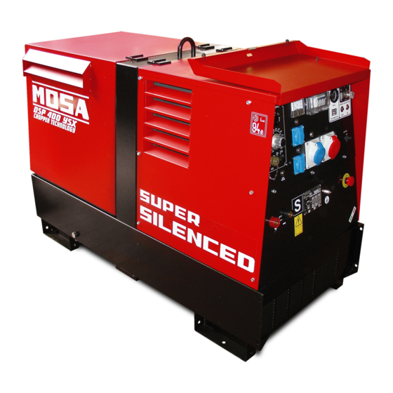
DESCRIPTION OF THE MACHINE DSP 400 YSX REV.1-06/12 The DSP 400 engine driven welder ia a unit which ensures the function as: a) a current source for arc welding b) a current source for the auxiliary power generation It is meant for industrial and professional use, powered by an endothermic engine; it is composed of various main parts such as: engine, alternator, electric and electronic controls, the fairing or a protective structure. - Page 3 · Competent support in the solution of problems; ofthe International Certification Network IQNet, · Information and training in the correct applicatio- awarded the official approval to MOSA after an- nand use of the products to assure the security examination of its operations at the head office ofthe operator and protect the environment;...
- Page 4 Index DSP 400 YSX REV.1-06/12 M 1.01 COPYRIGHT M 1.1 NOTES M 1.4 CE MARK M 1.5 TECHNICAL DATA M 1.6 TECHNICAL DATA ENGINE DRIVEN WELDER SYMBOLS AND SAFETY PRECAUTIONS M 2.1 SYMBOLS AND SAFETY PRECAUTIONS M 2.5 -…. INSTALLATION AND ADVICE BEFORE USE M 2.6...
- Page 5 (see page M1.1). All rights are reserved to said Company. It is a property logo of MOSA division of B.C.S. S.p.A. All other possible logos contained in the documen- tation are registered by the respective owners.
-
Page 6: Notes About The Manual
Notes REV.0-10/02 INFORMATION INFORMATION OF GENERAL TYPE In the envelope given together with the machine and/or Dear Customer, set you will find: the manual for Use Maintenance and We wish to thank you for having bought a high quality set. Spare Parts, the manual for use of the engine and the tools (if included in the equipment), the guarantee (in the Our sections for Technical Service and Spare Parts will... - Page 7 CE MARK REV.5-03/11 Any of our product is labelled with CE marking attesting its conformity to appliable directives and also the fulfillment of safety requirements of the product itself; the list of these directives is part of the declaration of conformity included in any machine standard equipment. Here below the adopted symbol: CE marking is clearly readable and unerasable and it can be either part of the data-plate.
-
Page 8: Dichiarazione Di Conformita
Dichiarazione conformità Konformitätserklärung Declaration of conformity Declaración de conformidad 1.4.1 Déclaration de conformité Declaração de conformidade REV.0-06/10 BCS S.p.A. Stabilimento di Cusago, 20090 (MI) - Italia V.le Europa 59 Sede legale: Tel.: +39 02 903521 Via Marradi 1 Fax: +39 02 90390466 20123 Milano - Italia DICHIARAZIONE DI CONFORMITA' Déclaration de Conformité... - Page 9 DSP 400 YSX Technical data REV.1-06/12 Technical data DSP 400 YSX GENERATOR Potenza trifase 12 kVA / 400 V / 17.3 A Potenza monofase 7 kVA / 230 V / 30.4 A Potenza monofase 5 kVA / 48 V / 104 A...
- Page 10 DSP 400 YSX Technical data REV.1-06/12 C.C. WELDING Welding current 400A/35% - 350A/60% - 300A/100% Starting voltage C.V. WELDING Welding current 350A/60% - 300A/100% Welding voltage 16 - 40V OUTPUT CARACTERISTIC SIMULTANEOUS UTILIZATION FACTORS In case Welding and Generation can be used simultaneously, however, the engine cannot be overloaded. The...
-
Page 11: Symbols In This Manual
SYMBOLS AND SAFETY PRECAUTIONS REV.0-11/99 SYMBOLS IN THIS MANUAL SAFETY PRECAUTIONS DANGEROUS The symbols used in this manual are designed to call your attention to important aspects of the operation of the machine as well as potential hazards and dangers This heading warns of an immediate danger for persons for persons and things. -
Page 12: Symbols And Safety Precautions
SYMBOLS AND SAFETY PRECAUTIONS REV.2-06/10 SYMBOLS PROHIBITIONS No harm for persons Use only with safety clothing - STOP - Read absolutely and be duly attentive It is compulsory to use the personal protection means given in equip- ment. Use only with safety clothing - Read and pay due attention It is compulsory to use the personal protection means given in equipment. - Page 13 INSTALLATION AND ADVICE BEFORE USE REV.0-06/00 The installation and the general advice concerning the operations, are finalized to the correct use of the ma- chine, in the place where it is used as generator group and/or welder. Stop engine when fueling Do not touch electric devices if you are barefoot or with wet Do not smoke, avoid flames, sparks or electric tools when fueling.
- Page 14 PRECAUTION (ENGINE DRIVEN WELDER) 2-5- REV.0-03/00 INSTALLATION AND ADVICE BEFORE USE The operator of the welder is responsible for the security of the people who work with the welder and for those in the vicinity. The security measures must satisfy the rules and regulations for engine driven welders. The information given below is in addition to the local security norms.
-
Page 15: Gasoline Engines
INSTALLATION AND ADVICE REV.1-06/07 Check that the air gets changed completely and the hot INSTALLATION AND ADVICE BEFORE USE air sent out does not come back inside the set so as to cause a dangerous increase of the temperature. GASOLINE ENGINES Use in open space, air swept or vent exhaust gases, which contain the deathly carbone oxyde, far from the work area. - Page 16 Installazione Luftzirkulation Installation DSP 400 YSX Installation REV.0-12/07...
- Page 17 Dimensioni Abmessungen Dimensions DSP 400 YSX 2.7.1 Installation REV.1-06/12 Ø13 1190 1610 Ø13 32.5...
- Page 18 UNPACKING REV.1-02/04 NOTE + Be sure that the lifting devices are: correctly mounted, adequate for the weight of the machine with it’s pack- aging, and conforms to local rules and regulations. When receiving the goods make sure that the product has not suffered damage during the transport, that there has not been rough handling or taking away of parts contained inside the packing or in the set.
- Page 19 TRANSPORT AND DISPLACEMENTS COVERED UNITS REV.1-06/10 NOTE Transportation must always take place with the engine off, electrical cables and starting battery disconnected and fuel tank empty. Be sure that the lifting devices are: correctly mounted, adequate for the weight of the machine with it’s packaging, and conform to local rules and regulations.
- Page 20 CTL400 ASSEMBLY REV.0-06/00 ATTENTION The CTL accessory cannot be removed from the machine and used separately (actioned manually or following vehicles) for the transport of loads or anyway for used different from the machine movements. TRAILERS The machines provided for assembling the CTL accessory (slow towing trolley) can be towed up to a maximum speed of 40 Kms/hour on asphalted surfaces.
- Page 21 Avoid accidentally spilling fuel. Clean RECOMMENDED OIL any eventual leaks before starting up MOSA recommends selecting AGIP engine oil. motor. Refer to the label on the motor for the recommended products. Refill the tank with good quality diesel fuel, such as automobile type diesel fuel, for example.
-
Page 22: Cooling Liquid
Set-up for operation Water cooled systems REV.1-02/11 GROUNDING CONNECTION COOLING LIQUID ATTENTION The grounding connection to an earthed installation is obligatory for all models equipped with a diffe- Do not remove the radiator tap with the rential switch (circuit breaker). In these groups the motor in operation or still hot, as the generator star point is generally connected to the liquid coolant may spurt out and cause... -
Page 23: Starting The Engine
STARTING THE ENGINE DSP 400 YSX REV.0-03/09 4. the motor starts up at its operating speed, 1500 Check daily or 1800 rpm. After start-up, allow the motor to run for a few minutes before powering on the utilities. See table;... -
Page 24: Stopping The Engine
STOPPING THE ENGINE DSP 400 YSX REV.0-03/09 STOP For shutdown under normal conditions, proceed as follows: 1. Break the welding process in course 2. Break the production of a.c. auxiliary generation dividing the loads or opening the GFI (D). 3.Let the engine run with no load for a few minutes. - Page 25 Comandi Bedienelemente Controls DSP 400 YSX Commandes REV.1-06/12 Pos. Descrizione Description Description Referenzliste Presa di saldatura (+) Welding socket ( + ) Prise de soudage ( + ) Schweißbuchse (+) Presa di saldatura (-) Welding socket ( - ) Prise de soudage ( - ) Schweißbuchse (-)
-
Page 26: Welding Cable Connection
USE AS A WELDER REV.1-03/02 ATTENTION Access to non qualified personnel is prohibited in proximity of these areas: - the control panel (front-end) - the engine exhaust fumes - the welding process. This symbol (regulation EN 60974-1 on safety requirements for arc welding apparatus) indi- cates that the engine driven welder is suitable for use in environments with an increased risk of electrical shock. -
Page 27: Getting Started
WELDING DIGITAL CONTROL REV.1-01/08 WELDING DIGITAL CONTROL CC-STICK ARC FORCE CELLULOSE 1 CELLULOSE 2 CONTACT STARTING CV-WIRE STAND-BY 400A RANGE POLARITY CURRENT CC INVERTER REMOTE CONTROL GETTING STARTED SETTING THE WELDING PROCESS 1) After having prepared the machine (charged the battery, put in oil and fuel) the machine is ready for operation. Before starting the engine please note the following: - The welder should only be operated by qualified personnel with experience in working with engine driven welders. - Check the oil level daily. Fuel should be put in before starting the engine. -
Page 28: Tig Mode
WELDING DIGITAL CONTROL REV.1-01/08 Inversion of polarity (Optional, available on TIG MODE request) Contact starting TIG This position is specifically for TIG welding. To create In order to invert polarity, press the switch on the the arc simply place the tip of the TIG electrode on remote control unit. the piece that requires welding then gently move By selecting “inversion” the “ON” LED switches off the tip away. The arc starts automatically and at the and the voltage at the welding socket becomes same time the welding current rises to the preset zero. The power contactor is witched inside the value, first using the welding current adjustment electrical box and the voltage reappears at the knob which is on the lower part of the control panel. - Page 29 WELDING DIGITAL CONTROL REV.1-01/08 WIRE FEEDER CONNECTED WITH REMOTE WARNING CONTROL CONNECTOR You can use the wire feeder only by respecting Wire feeder connection the pin configuration as shown on the below Connect the wire feeder to the welder with the wel- mentioned table. der turned off: -Welding cable between the machine’s (9) welding plug (+) and the wire feeder. “WIRE FEEDER connected without remote con- -Welding cable between the machine’s (10) welding trol connector” plug (-) and the piece to be welded. Welding voltage is always present on welding so- -Control/power cable between the machine’s con- ckets and also VRD is active.
-
Page 30: Thermal Protection
WELDING DIGITAL CONTROL USE AS A GENERATOR REV.1-06/10 minutes to allow the thermal WARNING protection to cool down. PUSH TO Before resetting by pressing It is strictly forbidden to connect the group to RESET the central button and then the public mains and/or to any other source connect the load again. -
Page 31: Accessory Use
REMOTE CONTROL ACCESSORY USE RC1 (PL Version) 38.9 RC1/90° (PL Version) REV.2-09/10 PUSH AND SCREW TIGHT PUSH AND SCREW TIGHT The remote control RC, which regulates the welding current in the CC (STICK welding) mode and the welding voltage in the CV (MIG/MAG welding), is connected to the front panel by means of a multipole connector. - Page 32 REMOTE CONTROL ACCESSORY USE (DSP/CT SERIES) 38.10 RC2/90° REV.3-12/11 PUSH AND SCREW TIGHT PUSH AND SCREW TIGHT The remote control RC, which regulates the welding current in the CC (STICK welding) mode and the welding voltage in the CV (MIG/MAG welding), is connected to the front panel by means of a multipole connector.
-
Page 33: Specification
PROTECTIONS EP7 ENGINE PROTECTION 39.13 REV.0-10/07 Description Specification The EP7 includes the basic safeguards to protect an DC Supply, Battery Plant 8V up to 36 Vdc Static Outputs (short circuit proof) 200 mAdc DIESEL engine. The EP7 features 7 LEDs, 3 Static Key Switch Rating 30 A (30 secs)/80 A (5 secs) Outputs and a 30A Key Switch. -
Page 34: Troubleshooting
TROUBLE SHOOTING DSP - EP5/EP7/ES 40.1 REV.0-05/05 PROBLEM POSSIBLE CAUSE WHAT TO DO WELDING P1 All functions performed by 1) Position of regulation poten- 1) Adjust the position of the WDC regulation knob on the potentiometer the WDC are regular, but tiometer incorrect knob spindle so that the potentiometer is not completely at the end of its there is no tension on the travel when the knob reaches its minimum position. - Page 35 TROUBLE SHOOTING DSP - EP5/EP7/ES 40.2 REV.3-09/07 PROBLEM POSSIBLE CAUSE WHAT TO DO WELDING WITH V.R.D. P10 The welding tension after 1) Net R.C. defective or disconnected 1) Check the net R.C. Check the connections. 3 sec isn’t less enough from + or - welding socket (plus in 12V dc) 2) WDC defective.
- Page 36 TROUBLE SHOOTING DSP - EP5/EP7/ES 40.3 REV.1-02/11 CHOPPER TEST CHECK THE FOLLOWING RESISTIVE VALUES ON THE CHOPPER CONNECTOR OUTPUT 18 Vca 10 Vca OUTPUT 18 Vca OUTPUT OUTPUT 25 Vca WIEW FROM INSERTION SIDE Check the resistive values between the following pairs of pins, by means of an ohmmeter.
- Page 37 TROUBLE SHOOTING DSP - EP5/EP7/ES 40.4 REV.0-05/05 Put the knob on RC1 at minimum/max, put one ohmmeter from pin A - B and measure the resistance. Knob Resistance Minimum 50 ÷ 100 Ω 4,5 - 4,7 KΩ DRAWING 4 P1 Supply connector P2 Chopper connector P3 Current sensor connector P4 - P5 Free DRAWING 5...
- Page 38 MAINTENANCE REV.0-06/10 WARNING ● Have qualified personnel do maintenance and troubleshooting work. ● Stop the engine before doing any work inside the machine. If for any reason the machine must be operated while working inside, pay at- tention moving parts, hot parts (exhaust manifold and muffler, etc.) electrical parts which may be unprotected when the machine is open.
-
Page 39: Gasoline Engine
STORAGE REV.0-06/07 In case the machine should not be used for more than 30 days, make sure that the room in which it is stored presents a suitable shelter from heat sources, weather changes or anything which can cause rust, corrosion or damages to the machine. - Page 40 CUST OFF REV.0-06/07 Have qualified personnel disassemble the In case of necessity for first aid and fire prevention, machine and dispose of the parts, including the see page M2.5. oil, fuel, etc., in a correct manner when it is to be taken out of service.
-
Page 41: Recommended Electrodes
RECOMMENDED ELECTRODES (In accordance with A.W.S Standard) REV.0-10/03 The information here below are to be intended only as indicative since the above norm is much larger. For further details please see the specific norms and/or the manufacturers of the product to be used in the welding process. - Page 42 ELECTRICAL SYSTEM LEGENDE REV.9-06/11 : Alternator : Stop push-button : Choke button : Wire connection unit : Ignition coil : Switch CC/CV : Capacitor : Spark plug : Connector – wire feeder : G.F.I. : Range switch : 420V/110V 3-phase transformer : Welding PCB transformer : Oil shut-down button : Switch IDLE/RUN : Fuse : Battery charge diode : Hz/V/A analogic instrument : 400V 3-phase socket : Relay : EMC filter : 230V 1phase socket : Resistor : Wire feeder supply switch : 110V 1-phase socket : Sparkler reactor : Wire feeder socket : Socket warning light : Output power unit : DSP chopper PCB : Hour-counter : Electric siren : Power chopper supply PCB : Voltmeter : E.P.4 engine protection : Switch and leds PCB : Welding arc regulator : Engine control PCB W6 : Hall sensor...
- Page 43 Schema elettrico Stromlaufplan DSP 400 YSX 61.1 Electric diagram REV.0-12/07...
- Page 44 Schema elettrico Stromlaufplan DSP 400 YSX 61.2 Electric diagram 400Y230Ix3 REV.0-12/07...
- Page 45 Schema elettrico Stromlaufplan DSP 400 YSX 61.3 Electric diagram AU Version REV.0-12/07...
- Page 46 Schema elettrico Stromlaufplan DSP 400 YSX 61.4 Electric diagram 400Y230I48I REV.0-12/07...
- Page 47 Schema elettrico Stromlaufplan DSP 400 YSX 61.5 Electric diagram REV.0-12/07...
- Page 48 Schema elettrico Stromlaufplan DSP 400 YSX 61.6 Electric diagram 400Y230Ix3 PL version REV.1-06/12...
- Page 49 Schema elettrico Stromlaufplan DSP 400 YSX 61.7 Electric diagram AU Version REV.1-06/12...
- Page 50 Schema elettrico Stromlaufplan DSP 400 YSX 61.8 Electric diagram 400Y230Ix3 / 400Y230I48I REV.1-06/12...
- Page 51 Schema elettrico Stromlaufplan DSP 400 YSX 61.9 Electric diagram PL / AU version REV.1-06/12...
-
Page 53: Spare Parts List
SPARE PARTS LIST REV.0-03/00 The manufacturer guarantees that any request for spare parts will be satisfied. To keep the machine in full working order, when replacement spare parts is required, always ask for genuine parts only. The requested data are to be found on the data plate located on the machine structure, quite visible and easy to consult. - Page 54 Ricambi Ersatzteile Spare parts Tabla de recambios DSP 400 YSX Piéces de rechange REV.0-06/12...
- Page 55 Ricambi Ersatzteile Spare parts Tabla de recambios DSP 400 YSX 56.1 Piéces de rechange REV.0-06/12 Pos. Cod. Descr. Note M107301390 ANELLO / RING FIXING FAN M700406020 VENTOLA / FAN M700406010 CONVOGLIATORE ARIA / CONVEYOR M107509005 GUARNIZIONE / GASKET M773748222 COPERTURA ALTERNATORE / COVER...
- Page 56 Ricambi Ersatzteile Spare parts Tabla de recambios DSP 400 YSX Piéces de rechange REV.0-06/12...
- Page 57 Ricambi Ersatzteile Spare parts Tabla de recambios DSP 400 YSX 57.1 Piéces de rechange REV.0-06/12 Pos. Cod. Descr. Note M105111550 VOLTMETRO FS 500V / VOLTMETER M220117130 COPERCHIO PROTEZIONE / PROTECTION COVER M105511810 CONTAORE 230V 50Hz IP65 / HOURMETER 230V 50Hz IP65...
- Page 58 Ricambi Ersatzteile Spare parts Tabla de recambios DSP 400 YSX Piéces de rechange REV.0-06/12...
- Page 59 Ricambi Ersatzteile Spare parts Tabla de recambios DSP 400 YSX 58.1 Piéces de rechange REV.0-06/12 Pos. Cod. Descr. Note M273119654 SCAT.PREOTEZ. SCHEDA SALD. / BOX PROTECTION PCB WELDER M282009869 TRASFORMATORE / TRANSFORMER M866817420 TELERUTTORE INVERS. POLARITA’ (compl.) / PLARITY CHANGE CONTACTOR PL Version M306479199 RELE’...
- Page 60 CTL 400 M217600140 REV.0-02/97 Pos. Cod. Descr. Descr. Note M0000217600141 GR.TIMONE, PIEDE X TRAINO LENTO KIT SITE TOW M102351750 PIEDE DI STAZIONAMENTO PARKING STAND M207401150 TIMONE TOW BAR M0000217600142 GR. ASSALE, RUOTE TRAINO LENTO KIT SITE TOW M207401160 ASSALE AXLE M102351740 RUOTA WHEEL...
- Page 61 RC1 - M936800000 (PL version) RC1/90° - M936820000 (PL version) REV.2-09/10 SCHEMA ELETTRICO RC1/90° ELECTRICAL DIAGRAM ELECTRIQUE SCHEMA ELEKTRISCHES SCHEMA Pos. Cod. Descr. Descr. M282009962 CAPPUCCIO M282009741 COMMUTATORE COMMUTATOR M308300543 MANOPOLA REGOLAZIONE COMPL. KNOB, REGULATOR COMPLETE M836709715 POTENZIOMETRO WELDING CURRENT REGULATOR M836709910 CONNETTORE FEMMINA FEMALE CONNECTOR...
- Page 62 RC2 - M936840000 (BC version) RC2/90° - M936850000 (BC version) REV.0-09/10 RC2/90° SCHEMA ELETTRICO ELECTRICAL DIAGRAM ELECTRIQUE SCHEMA ELEKTRISCHES SCHEMA Pos. Cod. Descr. Descr. M308300543 MANOPOLA REGOLAZIONE COMPL. KNOB, REGULATOR COMPLETE M836709715 POTENZIOMETRO WELDING CURRENT REGULATOR M836709910 CONNETTORE FEMMINA FEMALE CONNECTOR M836700524 SCATOLA M308309900...
Need help?
Do you have a question about the DSP 400 YSX and is the answer not in the manual?
Questions and answers