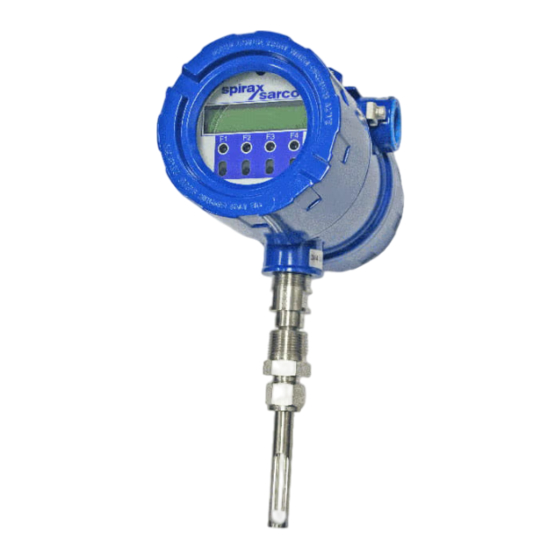
Spirax Sarco MTI10 Insertion Installation And Maintenance Instructions Manual
Thermal mass flowmeter and temperature transmitter
Hide thumbs
Also See for MTI10 Insertion:
- Installation and maintenance instructions manual (126 pages)
Table of Contents
Advertisement
Quick Links
Advertisement
Table of Contents
Troubleshooting

Related Manuals for Spirax Sarco MTI10 Insertion


Summary of Contents for Spirax Sarco MTI10 Insertion
- Page 1 IM-S65-01-US Issue 1 Thermal Mass Flowmeter and Temperature Transmitter MTI10 Insertion and MTL10 Inline Installation and Maintenance Instructions Thermal Mass Flowmeter and Temperature Transmitter MTI10 Insertion and MTL10 Inline © Copyright 2023 IM-S65-01-US Issue 1 Printed in US...
- Page 2 Please note that Spirax Sarco. reserves the right to change and/or improve the product design and specification without notice. All Spirax Sarco Manuals and software for the MTI10/MTL10 are available in English only.
-
Page 3: Table Of Contents
2. Installation General Insertion type Inline type 3. Wiring (Electrical) General Input power Signal Wiring NE-43 alarms Frequency/Alarm Output Wiring Remote switch Remote sensor option Remote switch Thermal Mass Flowmeter and Temperature Transmitter MTI10 Insertion and MTL10 Inline IM-S65-01-US Issue 1... - Page 4 5.13 Performing the Zero CAL-CHECK® Calibration Validation Test 5.14 Performing the Zero CAL-CHECK® - In the Pipe 5.15 Performing the Zero CAL-CHECK® - Out of Pipe 5.16 Troubleshooting CAL-V™ 5.17 Troubleshooting Zero CAL-CHECK® Thermal Mass Flowmeter and Temperature Transmitter MTI10 Insertion and MTL10 Inline IM-S65-01-US Issue 1...
- Page 5 9. Appendices Specifications Agency Approvals MTI10/MTL10 with 2 Gas Curves Dimensions Installation Variations (moisture) Installation Variations (limited space) Warranty Out of Warranty Conditions Returning your meter Thermal Mass Flowmeter and Temperature Transmitter MTI10 Insertion and MTL10 Inline IM-S65-01-US Issue 1...
-
Page 6: Introduction
(NM3/hr, NLPM) with no additional temperature or pressure measurements required. 1.3 Calibration validation Spirax Sarco has developed a method to validate the calibration of the flowmeter in the field. This method is called Calibration Validation and it is made up of two distinct tests: CAL-V™ and Zero CAL- CHECK®. - Page 7 1.4 Flow calibration Spirax Sarco maintains instrument calibration records on every flowmeter. This data can also be accessed via a computer using MTI10/MTL10 View software within the instrument. Computer-generated calibration documents describe specific instrument details that can be sorted by serial number, tag number or customer purchase order.
- Page 8 Optional Display and Configuration Panel Frequency or Alarm Contact Input Standard Digital Communications (Free meter View Software) Optional Digital Communications RS485 Modbus Fig. 2 - Functional Diagram Thermal Mass Flowmeter and Temperature Transmitter MTI10 Insertion and MTL10 Inline IM-S65-01-US Issue 1...
-
Page 9: Installation
2. Installation 2.1 General 2.1.1 Scope This section describes how to install the Spirax Sarco MTI10/MTL10 Flowmeter and how to get started. Installation methods will vary according to the flowmeter type (insertion or inline). For Insertion Types (MTI10): Determine lateral position on the pipe... -
Page 10: Insertion Type
2.2.1 Instructions for Insertion Flowmeter Lateral Placement Install the Model MTI10 Insertion style flowmeter so that it is far enough away from bends in the pipe, obstructions, or changes in line sizes to ensure a consistent flow profile. Fifteen diameters of straight pipe upstream and ten downstream are recommended. -
Page 11: Inline Type
(Supplied by Spirax Sarco) Half Coupling, ¾" NPT Female(Supplied byCustomer) Customer’s Pipe 22 mm (0.87") Fig. 4 - Cross Section of Insertion Sensor Depth in Pipe Thermal Mass Flowmeter and Temperature Transmitter MTI10 Insertion and MTL10 Inline IM-S65-01-US Issue 1... - Page 12 (see figure 7). The sensor type supplied was selected at the factory to be the best suited for your application. Follow the appropriate sensor orientation instructions. +2° -2° Thermal Mass Flowmeter and Temperature Transmitter MTI10 Insertion and MTL10 Inline IM-S65-01-US Issue 1...
- Page 13 2.2.4 Equal Length Sensor Elements Install flowmeter with both sensor elements facing the flow stream within ±3 mm (0.1"). +2° Flow -2° Flow Fig. 7 - Equal Length Sensor Elements Thermal Mass Flowmeter and Temperature Transmitter MTI10 Insertion and MTL10 Inline IM-S65-01-US Issue 1...
- Page 14 Fig. 8 - Proper Tightening of the Compression Fitting Nut While holding the fitting body steady, tighten the nut one and one-quarter turn to the 9 o'clock position. Thermal Mass Flowmeter and Temperature Transmitter MTI10 Insertion and MTL10 Inline IM-S65-01-US Issue 1...
- Page 15 See Figure 9 for a detailed look at upstream and downstream pipe diameters for inline meters. Proper Profile Flow 8 x Pipe ID 4 x Pipe ID Irregular Profile Fig. 9 - Upstream and Downstream Pipe IDs for Inline Meters Thermal Mass Flowmeter and Temperature Transmitter MTI10 Insertion and MTL10 Inline IM-S65-01-US Issue 1...
- Page 16 Fig. 10 - Orientation of an Inline Meter - Directional Arrows 2.3.3 Tightening Compression Fittings The compression fitting has been placed according to the proper depth in the flow body by Spirax Sarco factory technicians. After the flow body has been correctly fitted to the process pipe, the compression fitting may need to be tightened correctly (Figure 8 on p.
-
Page 17: Wiring (Electrical)
AC ground terminal or instrumentation AC ground. Do not route the power and signal wires in the same conduit. Power wires must enter left-hand conduit entry. Signal and remote sensor (where applicable) must enter right-hand conduit entry. Thermal Mass Flowmeter and Temperature Transmitter MTI10 Insertion and MTL10 Inline IM-S65-01-US Issue 1... - Page 18 Trim the wires to extend 2.5 inches out of the enclosure after the conduit and wires are routed to the MTI10/MTL10 (preferred method). Trim the wires to extend 6 inches from the end of the conduit before it is attached to the MTI10/ MTL10. Thermal Mass Flowmeter and Temperature Transmitter MTI10 Insertion and MTL10 Inline IM-S65-01-US Issue 1...
-
Page 19: Input Power
A power failure or resetting the total will cause the Contract Time to change. Data Logger with a Real Time Clock (RTC) option should be used to avoid this. Thermal Mass Flowmeter and Temperature Transmitter MTI10 Insertion and MTL10 Inline IM-S65-01-US Issue 1... - Page 20 Wh 5 4-20 PULSE 24V, 0.75A Fig. 13 - Connections for optional AC Power Supply connection wiring must be rated for at least 90°C (194° F). Caution Thermal Mass Flowmeter and Temperature Transmitter MTI10 Insertion and MTL10 Inline IM-S65-01-US Issue 1...
-
Page 21: Signal Wiring
PLC or DCS. Some PLC/DCS equipment has the load resistor built in to the unit; please refer to the PLC/DCS technical manual. Do not exceed a 600 ohm load on the MTI10/ MTL10 Flowmeter 4-20 mA signal. Thermal Mass Flowmeter and Temperature Transmitter MTI10 Insertion and MTL10 Inline IM-S65-01-US Issue 1... - Page 22 PLC or DCS. Some PLC/DCS equipment has the load resistor built in to the unit; please refer to the PLC/DCS technical manual. Do not exceed a 600 ohm load on the MTI10/ MTL10 Flowmeter 4-20 mA signal. Thermal Mass Flowmeter and Temperature Transmitter MTI10 Insertion and MTL10 Inline IM-S65-01-US Issue 1...
-
Page 23: Alarms
24 Vdc Return 24V , 0.75A NAMUR Alarm Range 0 mA Fig. 16 - 4-20 mA Failsafe Wiring and Range of 4-20 mA Output for NAMUR Alarm Thermal Mass Flowmeter and Temperature Transmitter MTI10 Insertion and MTL10 Inline IM-S65-01-US Issue 1... -
Page 24: Frequency/Alarm Output Wiring
The output of a solid state relay may, in turn, operate loads such as electromechanical relays or alarm indicators. Fig. 17 - Frequency/Alarm Output Isolated (Recommended) Red 1 Red2 Yel 3 REMOTE SENSOR 4-20 Wh 4 FLOW Wh 5 4-20 Thermal Mass Flowmeter and Temperature Transmitter MTI10 Insertion and MTL10 Inline IM-S65-01-US Issue 1 PULSE /ALM... - Page 25 Do not exceed 42 mA total load on the 24V Output TS4 (i.e. including 4-20 mA outputs). Caution Fig. 18 - Frequency/Alarm Output Local +24V Power Option Thermal Mass Flowmeter and Temperature Transmitter MTI10 Insertion and MTL10 Inline IM-S65-01-US Issue 1...
-
Page 26: Remote Switch
External switch 24V, 0.75A Fig. 19 - Remote Switch Wiring If you have purchased Modbus RTU (RS485) communications, please refer to the Modbus chapter in the manual. Thermal Mass Flowmeter and Temperature Transmitter MTI10 Insertion and MTL10 Inline IM-S65-01-US Issue 1... -
Page 27: Remote Sensor Option
3.7 Remote sensor option 3.7.1 Remote Wiring Remote wiring will be the same for both MTI10 insertion and MTL10 inline flowmeters. Signal Wiring 2 x ¾ " NPT, Female Remote Cable, 5 Conductor, Shielded, 100ft (30.48m) Max. Fig. 20 - Remote Wiring Signal Wiring includes: 4-20 mA, pulse, alarm output, contact input, remote switch, USB, and communications options. -
Page 28: Remote Switch
Electronics Enclosure Extension Cable Remote Enclosure Sensor Wire Color Terminal Numbers Wire Color Terminal Numbers Black Brown Yellow No Connection Shield Green White White Green White Thermal Mass Flowmeter and Temperature Transmitter MTI10 Insertion and MTL10 Inline IM-S65-01-US Issue 1... - Page 29 Shield WH T WH T Black Dot Denotes Pin #1 Sensor Wires Probe Sensor Wired at Factory Sensor Remote Enclosure Thermal Mass Flowmeter and Temperature Transmitter MTI10 Insertion and MTL10 Inline IM-S65-01-US Issue 1...
-
Page 30: Operation
The USB interface is a standard feature which allows communication to a PC in order to monitor readings and configure settings. MTI10/MTL10 View, is a free application program from Spirax Sarco that connects to the USB interface and allows data monitoring, configuration setting, data logging to Excel®, and an option to save and recall MTI10/MTL10 configuration data. -
Page 31: Display Screens
(Fixed screen) Elp = 14.6 HR Set Parameter? Display #4 (Fixed screen) Enter programming screen Requires password. Default is 1234. Fig. 23 - MTI10/MTL10 Display Screen Navigation Thermal Mass Flowmeter and Temperature Transmitter MTI10 Insertion and MTL10 Inline IM-S65-01-US Issue 1... -
Page 32: Engineering Displays
Pressing the F1 and F2 keys at the same time in the normal mode, brings up the engineering displays. csv=0.3432 Volt These displays show internal parameters of the MTI10/MTL10 which are used by Spirax Sarco service CsvAv=366809 technicians. Press F4 to exit. Use the F1 and F2 keys to navigate. -
Page 33: Programming
Press NXT (F1) key repeatedly until the correct selection is made and OK (F4) key to accept the entry. SET PARAMETERS ? SET PARAMETERS ? SET PARAMETERS ? Thermal Mass Flowmeter and Temperature Transmitter MTI10 Insertion and MTL10 Inline IM-S65-01-US Issue 1... - Page 34 Press EXIT (F4) repeatedly until “Normal Mode" is seen briefly to exit the programming mode. EXIT EXIT 4-20 4-20 EXIT EXIT 20 mA = 3751 SCFM 20 mA = 3751 SCFM Thermal Mass Flowmeter and Temperature Transmitter MTI10 Insertion and MTL10 Inline IM-S65-01-US Issue 1...
- Page 35 Pulse/Alarm Output to System alarm as shown in "Setting Up the NE-43 Alarms" . mA Fault = 3.6 mA Caution Thermal Mass Flowmeter and Temperature Transmitter MTI10 Insertion and MTL10 Inline IM-S65-01-US Issue 1...
- Page 36 When the flow rate exceeds the programmed value for the 20mA set point, the analog output will stay at 20mA and an alarm code will be generated. Thermal Mass Flowmeter and Temperature Transmitter MTI10 Insertion and MTL10 Inline IM-S65-01-US Issue 1...
- Page 37 When data is entered with any of the three described methods, the other values will be re-calculated according to the settings. PLS/UNT = 1.2 PLS/UNT = 1.2 Thermal Mass Flowmeter and Temperature Transmitter MTI10 Insertion and MTL10 Inline IM-S65-01-US Issue 1...
- Page 38 If the flow rate exceeds the maximum pulse rate (frequency), the output will stay at 100 Hz and the MTI10/MTL10 will issue an alarm code. EXIT Thermal Mass Flowmeter and Temperature Transmitter MTI10 Insertion and MTL10 Inline EXIT IM-S65-01-US Issue 1...
- Page 39 = High Flow Alarm LoFloAlm = Low Flow Alarm HiTempAlm = High Temperature Alarm LoTempAlm = Low Temperature Alarm System Alm = System Alarm Not used Frequency Thermal Mass Flowmeter and Temperature Transmitter MTI10 Insertion and MTL10 Inline IM-S65-01-US Issue 1...
- Page 40 Switch Crv = Switch between calibration curve 1 and 2 (only if 2 gas curve ordered) EXIT Press EXIT (F4) repeatedly until you exit programming mode. EXIT Comm=Modbus Comm=Modbus Thermal Mass Flowmeter and Temperature Transmitter MTI10 Insertion and MTL10 Inline IM-S65-01-US Issue 1...
- Page 41 Baud rate (for Modbus selection only) Baud=9600 Press NXT (F1) to select the baud rate and press OK (F4) Selections are: 19200 9600 4800 2400 1200 Parity=NONE Thermal Mass Flowmeter and Temperature Transmitter MTI10 Insertion and MTL10 Inline Address = 01 IM-S65-01-US Issue 1...
- Page 42 Address = 01 Press CHG (F1) to change the Modbus address and then press OK (F4). To avoid conflicts on the Modbus this must be a unique address Thermal Mass Flowmeter and Temperature Transmitter MTI10 Insertion and MTL10 Inline IM-S65-01-US Issue 1...
- Page 43 Display 1, Line 1 DSP1L2 Display 1, Line 2 DSP2L1 Display 2, Line 1 DSP2L2 Display 2, Line 2 SET PARAMETERS SET PARAMETERS EXIT EXIT EXIT EXIT Thermal Mass Flowmeter and Temperature Transmitter MTI10 Insertion and MTL10 Inline IM-S65-01-US Issue 1...
- Page 44 This menu allows you to alternate between menu display 1 and 2 every few seconds. Selections are: On Press OK (F4) to accept selection. Press EXIT (F4) repeatedly until “Normal Mode" is seen briefly to exit the programming mode. Thermal Mass Flowmeter and Temperature Transmitter MTI10 Insertion and MTL10 Inline IM-S65-01-US Issue 1...
- Page 45 The second password is used to allow access to calibration factors and should normally never be changed unless advised by the Spirax Sarco Technial Support, or to set a new password in the event that the user forgets the Level 1 password.
- Page 46 Lbs/time or Kg/time. These values will be set at Spirax Sarco, using the Application Data Sheet values. If the customer changes the application, these values can be changed to match the new application. Check with Spirax Sarco Technical Support before changing the application gas.
- Page 47 PresRef= 14.7 PresRef= 14.7 PresRef= 14.7 Press CHG (F1) to change it and OK (F4) to accept. Thermal Mass Flowmeter and Temperature Transmitter MTI10 Insertion and MTL10 Inline DNS = 0.988876 KG/m3 DNS = 0.988876 KG/m3 DNS = 0.988876 KG/m3...
- Page 48 The CAL and SPC function key will only appear and be accessible from a Level 2 password. Then press PRM (F3). CUTOFF = 2.0 SCFM CUTOFF = 2.0 SCFM CUTOFF = 2.0 SCFM Thermal Mass Flowmeter and Temperature Transmitter MTI10 Insertion and MTL10 Inline IM-S65-01-US Issue 1...
- Page 49 Enter the pipe area in square meters or square feet and then press OK (F4). Use square meter for metric flow unit selection and square feet for English flow unit selection. FILTER = 0.8 Thermal Mass Flowmeter and Temperature Transmitter MTI10 Insertion and MTL10 Inline IM-S65-01-US Issue 1...
- Page 50 Enter the filter value and then press OK (F4). Filter Response (Sec.) 65% of Target 0.09 0.10 0.15 0.20 0.25 0.30 0.35 0.40 0.60 1.00 0.05 2.00 0.03 3.00 0.01 10.3 Thermal Mass Flowmeter and Temperature Transmitter MTI10 Insertion and MTL10 Inline IM-S65-01-US Issue 1...
- Page 51 If the programming menu was entered with a Level 2 password, then more menus will be shown that deal with factory set parameters that should not be changed. Thermal Mass Flowmeter and Temperature Transmitter MTI10 Insertion and MTL10 Inline IM-S65-01-US Issue 1...
- Page 52 Calibration parameter values are set for temperature and pressure at 0 degree C and 760 mmHg. Note! These settings should normally never be changed except by Spirax Sarco personnel at the factory. This menu is entered from the base menu and pressing FLO, PRM and CAL.
- Page 53 All current user-entered settings will be overwritten. The green LP1 LED will flash at a faster pace until the recall is performed. The "RESET CRC" screen will follow "RESTORE DATABASE". Thermal Mass Flowmeter and Temperature Transmitter MTI10 Insertion and MTL10 Inline IM-S65-01-US Issue 1...
- Page 54 Reset CRC If the NVRAM CRC check fails (Error Code 36), the programmed settings values will need to be verified and corrected before clearing the error. Call Spirax Sarco Technial Support if you need assistance. RESET CRC? Press YES (F1) ONLY if you want to reset the CRC and generate a new CRC value.
- Page 55 Press YES (F1) to start the simulation mode, otherwise press NO (F4). Upon pressing either key, the program will return to the FLOW PARAMETER 1 menu. Note! Simulation Mode will be cleared if the power is cycled. Thermal Mass Flowmeter and Temperature Transmitter MTI10 Insertion and MTL10 Inline IM-S65-01-US Issue 1...
- Page 56 To select what the flow output will do during a CAL-V, choose from these options: Go To Zero: Flow output will be zero during the test (i.e. 4mA) Hold Value: Flow will hold last value during the test Thermal Mass Flowmeter and Temperature Transmitter MTI10 Insertion and MTL10 Inline IM-S65-01-US Issue 1...
- Page 57 For applications with temperature exceeding 250°F (121°C), CAL-V™ test results may vary. Caution Periodic inspection for damage and cleaning of the sensor elements is required. Thermal Mass Flowmeter and Temperature Transmitter MTI10 Insertion and MTL10 Inline IM-S65-01-US Issue 1...
- Page 58 See the Calibration Validation Chapter for details on performing all diagnostic tests. Please use the PVC sensor cover that was shipped with your meter perform Zero CAL-CHECK® tests out of pipe ("ZERO BTL TEST"). Thermal Mass Flowmeter and Temperature Transmitter MTI10 Insertion and MTL10 Inline IM-S65-01-US Issue 1...
- Page 59 Diff = xx.xx T=xx Sd = x.xe-xx T=xx Diff = xx.xx T=xx Sd = x.xe-xx T=xx Verifying ZRO Verifying ZRO Diff = xx.xx T=xx Sd = x.xe-xx T=xx Thermal Mass Flowmeter and Temperature Transmitter MTI10 Insertion and MTL10 Inline IM-S65-01-US Issue 1...
- Page 60 To return to the normal display mode, use mechanical buttons or wait for the programming mode timeout. Thermal Mass Flowmeter and Temperature Transmitter MTI10 Insertion and MTL10 Inline IM-S65-01-US Issue 1...
- Page 61 Use buttons (F1) (F2) and (F3) to enter "0000" then press OK (F4). Turn OFF power to the MTI10/MTL10. Turn ON power to the MTI10/MTL10 while placing your finger on the (F1) IR key. Thermal Mass Flowmeter and Temperature Transmitter MTI10 Insertion and MTL10 Inline IM-S65-01-US Issue 1...
-
Page 62: Menu Tree
2400 4800 9600 19200 Modbus NONE Parity=EVEN only EVEN Address=02 01-24 7 Digital Output Menu, p. 64 Fig. 25 - MTI10/MTL10 Menu Tree - Main Menu Thermal Mass Flowmeter and Temperature Transmitter MTI10 Insertion and MTL10 Inline IM-S65-01-US Issue 1... - Page 63 20 mA=2345.6 SCFM Level 2 4mACnt=274 4 mA=0 SCFM 20 mA=300 °F mA Fault=Not use No t us e 3.6 mA 21 mA 4 mA=0 °F Thermal Mass Flowmeter and Temperature Transmitter MTI10 Insertion and MTL10 Inline IM-S65-01-US Issue 1...
- Page 64 High Temp Alarm OUT= HiTmpAlm HiTmpAlm=300° F Low Temp Alarm OUT= LoTmpAlm System Alarm OUT= System Alm LoTmpAlm=10 F Fig. 26 - MTI10/MTL10 Menu Tree - Digital Output Thermal Mass Flowmeter and Temperature Transmitter MTI10 Insertion and MTL10 Inline IM-S65-01-US Issue 1...
- Page 65 Select 1 of 3 methods to scal e OUT= FREQUENCY th e frequenc y output FREQUENCYOUTPUT U/ P FEQ EXIT PLS/UNT=2 UNT/PLS=0.5 MaxFreq=100H z MaxFlo=5678. 5 SCFM Thermal Mass Flowmeter and Temperature Transmitter MTI10 Insertion and MTL10 Inline IM-S65-01-US Issue 1...
- Page 66 DIAGNOSTIC EXIT FloSim=0 SCFM TmpSim=0 ° F CsvSim=0 V ENABLE SIM? Diagnostic Test Menu, p. 72 Fig. 27 - MTI10/MTL10 Menu Tree - Parameter Menu 1 Thermal Mass Flowmeter and Temperature Transmitter MTI10 Insertion and MTL10 Inline IM-S65-01-US Issue 1...
- Page 67 Flow Parameter 2 Menu, p. 68 FLO UNT=SCFM TMP UNT=° F TmpRef= 0 °F PRES UNT=mmHG PresRef=76 0 Thermal Mass Flowmeter and Temperature Transmitter MTI10 Insertion and MTL10 Inline IM-S65-01-US Issue 1...
- Page 68 CHG PRV NXT EXIT Volt20 = 1.2479 CHG PRV NXT EXIT Flo20 = 7046.5 CHG PRV NXT EXIT Fig. 28 - MTI10/MTL10 Menu Tree - Parameter Menu 2 Thermal Mass Flowmeter and Temperature Transmitter MTI10 Insertion and MTL10 Inline IM-S65-01-US Issue 1...
- Page 69 High Flow Alarm in selected unit Low Flow Alarm in selected unit LoFloAlm= 0 SCFM HiTempAlm=0 °F High Temperature Alarm in selected unit Low Temperature Alarm in selected unit LoTempAlm=0 °F Thermal Mass Flowmeter and Temperature Transmitter MTI10 Insertion and MTL10 Inline IM-S65-01-US Issue 1...
- Page 70 When alternate FLo rate "ON", flashes DSP2L2=Elps Tota l between the 2 Elps displays Temp Alarm ALTERNATE=Off Fig. 29 - MTI10/MTL10 Menu Tree - Display Menu Thermal Mass Flowmeter and Temperature Transmitter MTI10 Insertion and MTL10 Inline IM-S65-01-US Issue 1...
- Page 71 Total = Total flow of process gas Elps = Elapsed time since reset of flow total Temp = Temperature of process gas Alarm = High/Low Flow Rate or Temperature Alarm Thermal Mass Flowmeter and Temperature Transmitter MTI10 Insertion and MTL10 Inline IM-S65-01-US Issue 1...
- Page 72 Verifying ZR O Diff=x.xx T=xx Sd=x.xe-xx T=xx Diff=x.xxx % Pass Flow Parameter 1 Menu, p. 66 Fig. 30 - MTI10/MTL10 Menu Tree - Diagnostic Tests Menu Thermal Mass Flowmeter and Temperature Transmitter MTI10 Insertion and MTL10 Inline IM-S65-01-US Issue 1...
- Page 73 ZR=x.xxxxx T=xx EXIT Ref=x.xxx x VERIFY ZRO? Process Zero and Stable? EXIT YES Verifying ZR O Verifying ZR O Diff=x.xx T=xx Sd=x.xe-xx T=xx Diff=x.xxx % Pass Thermal Mass Flowmeter and Temperature Transmitter MTI10 Insertion and MTL10 Inline IM-S65-01-US Issue 1...
-
Page 74: Calibration
5. Calibration The Spirax Sarco MTI10/MTL10 View software allows users to easily display data and configure the MTI10/ MTL10 to their specific application parameters. Then, log flow/temperature data to an Excel® file. The software can also activate the Spirax Sarco CAL-V™ and Zero CAL-CHECK® diagnostic functions. - Page 75 The figure above illustrates the Calibration Validation feature and a summary of the details for each of the two tests. Spirax Sarco has developed Calibration Validation, using the CAL-V™ and Zero CAL-CHECK® tests to help our customers avoid sending the meter back for annual or biennial re-calibrations.
-
Page 76: Cal-V™ Calibration Validation Test
Sensor Sensor Control Control SENSOR SIGNAL SENSOR SIGNAL Signal PROCESSING Signal PROCESSING ELECTRONICS ELECTRONICS PowerPro™ Sensor PowerPro™ Sensor Fig. 32 - Normal Mode vs. CAL-V™ Mode Thermal Mass Flowmeter and Temperature Transmitter MTI10 Insertion and MTL10 Inline IM-S65-01-US Issue 1... -
Page 77: Zero Cal-Check® Calibration Validation Test
VOLTAGE AT ZERO PROPORTIONAL TO FLOW RATE FLOW RATE PowerPro™ Sensor PowerPro™ Sensor Process Flow “No Flow" Condition Fig. 33 - Normal Mode vs. Zero CAL-CHECK® Mode Thermal Mass Flowmeter and Temperature Transmitter MTI10 Insertion and MTL10 Inline IM-S65-01-US Issue 1... -
Page 78: Starting Up Cal-V
Due to the high sensitivity of the PowerPro™ sensor, it is necessary to isolate the sensor once the meter has been removed from the pipe. Therefore, Spirax Sarco provides a sensor cover when the meter is shipped to the customer. An alternative to the sensor cover is to use a bottle or other closed container in order to isolate the sensor and achieve the "no flow"... -
Page 79: Setting Field Baseline For In-Situ Zero Cal-Check® Tests
"Starting the Field Baseline Set" on p. 83. Note! If you need information on the installation of the Packing Gland Assembly, refer to the Document 105440. Thermal Mass Flowmeter and Temperature Transmitter MTI10 Insertion and MTL10 Inline IM-S65-01-US Issue 1... - Page 80 Fig. 35 - MTI10/MTL10 and Parts of the Packing Gland Assembly Small Nut Adjacent Hex Fittings Large Nut End Fitting Fig. 36 - Close-Up: Fittings of the Packing Gland Assembly Thermal Mass Flowmeter and Temperature Transmitter MTI10 Insertion and MTL10 Inline IM-S65-01-US Issue 1...
- Page 81 Close the Valve Shut-off handle by turning the lever 90˚clockwise to isolate the sensor within the chamber of the Packing Gland Assembly. Then slightly tighten the compression fitting to keep a seal in the chamber. Thermal Mass Flowmeter and Temperature Transmitter MTI10 Insertion and MTL10 Inline IM-S65-01-US Issue 1...
- Page 82 Check to be sure the meter has returned to normal operation Thermal Mass Flowmeter and Temperature Transmitter MTI10 Insertion and MTL10 Inline IM-S65-01-US Issue 1...
-
Page 83: Starting The Field Baseline Set
ZERO CHK MENU ZERO CHK MENU ZERO CHK MENU ZERO CHK MENU ZERO CHK MENU EXIT EXIT EXIT EXIT EXIT Choose PIP (F1) for in-situ Zero CAL-CHECK®. Thermal Mass Flowmeter and Temperature Transmitter MTI10 Insertion and MTL10 Inline IM-S65-01-US Issue 1... - Page 84 Ref=x.xxxx Press OK (F4) to return to the Zero CAL-CHECK® menu. The meter may now perform Zero CAL-CHECK® tests at the Field Baseline at any time. Thermal Mass Flowmeter and Temperature Transmitter MTI10 Insertion and MTL10 Inline IM-S65-01-US Issue 1...
-
Page 85: Performing The Cal-V™ Calibration Validation Test
To select what the flow output will do during CAL-V™, choose from these options: Go To Zero: Flow output will be zero during the test (ie 4mA) Hold Value: Flow will hold last value during the test Thermal Mass Flowmeter and Temperature Transmitter MTI10 Insertion and MTL10 Inline IM-S65-01-US Issue 1... - Page 86 2 during this test. Passed Passed CAL-V = 0.51 Passed CAL-V = 0.51 Passed Upon test completion, the final CAL-V™ value will be displayed along with a Pass/Fail message. Thermal Mass Flowmeter and Temperature Transmitter MTI10 Insertion and MTL10 Inline IM-S65-01-US Issue 1...
-
Page 87: Performing The Zero Cal-Check® Calibration Validation Test
"no flow" condition must be created. If performing out of the pipe, the meter must be removed and the sensor protected by a bottle ZERO CHK MENU ZERO CHK MENU ZERO CHK MENU ZERO CHK MENU EXIT EXIT EXIT EXIT Thermal Mass Flowmeter and Temperature Transmitter MTI10 Insertion and MTL10 Inline IM-S65-01-US Issue 1... -
Page 88: Performing The Zero Cal-Check® - In The Pipe
This test will take less than 5 minutes. The T=xx is a count down timer indicating how much time is left to finish the test. Passed Passed Passed Passed Passed Upon test completion, the final percentage value will be displayed along with a Pass/Fail message. Thermal Mass Flowmeter and Temperature Transmitter MTI10 Insertion and MTL10 Inline IM-S65-01-US Issue 1... -
Page 89: Performing The Zero Cal-Check® - Out Of Pipe
ZERO CHK MENU EXIT EXIT EXIT EXIT Press BTL (F2) to choose to perform the test out of the pipe. The display will show: ZERO BTL TEST EXIT Thermal Mass Flowmeter and Temperature Transmitter MTI10 Insertion and MTL10 Inline IM-S65-01-US Issue 1... - Page 90 The T=xx is a count down timer indicating how much time is left to finish the test. Passed Passed Passed Passed Upon test completion, the final value will be displayed along with a Pass/Fail message. Thermal Mass Flowmeter and Temperature Transmitter MTI10 Insertion and MTL10 Inline IM-S65-01-US Issue 1...
-
Page 91: Troubleshooting Cal-V
If the MTI10/MTL10 Flowmeter fails a CAL-V™ Calibration Validation test, the meter must be returned to the factory for evaluation. See the "Returning Your Meter" section in the Appedix of this Installation and Instruction Guide or contact Spirax Sarco Applications at 1-800-883-4411 for information on how to return the meter. -
Page 92: Modbus Rtu (Rs485)
6. MODBUS 6.1 Scope This section describes the Modbus RTU (RS485) implementation for the Spirax Sarco MTI10/MTL10 Mass Flow Meter based on the Modicon Modbus Protocol (PI-MBUS-300 Rev. J). Modbus RTU (RS485) is an application layer messaging protocol that provides client/server communications between devices. - Page 93 Temperature in selected units 0x19 40026 Temperature in selected unit (float, upper 16 bits) Temperature in selected units 0x1A 40027 Temperature in selected unit (float, lower 16 bits) Thermal Mass Flowmeter and Temperature Transmitter MTI10 Insertion and MTL10 Inline IM-S65-01-US Issue 1...
- Page 94 Total 24 hrs, Record day 7 , low register Tot24hrs :Record day 7 0x35 40054 Total 24 hrs, Record day 7 , high register Tot24hrs: Record day 7 Thermal Mass Flowmeter and Temperature Transmitter MTI10 Insertion and MTL10 Inline IM-S65-01-US Issue 1...
- Page 95 <0x01> <0x03> <0x00> <0x00> <0x00> <0x01> <0x0a> <0x84> 6.2.2 Command Response: <0x01> <0x03> <0x02> <xx> <xx> <CRC high> <CRC low> Where xx xx is the data register value. Thermal Mass Flowmeter and Temperature Transmitter MTI10 Insertion and MTL10 Inline IM-S65-01-US Issue 1...
-
Page 96: Read Input Register (Mti10/Mtl10 Status And Status 2 Command 04)
Check analog output settings Busy Check wiring from RS485 to Anybus IC Bridge Shutdown Check RTC CRC error Check parameters and reset CRC Tot Error Reset total Thermal Mass Flowmeter and Temperature Transmitter MTI10 Insertion and MTL10 Inline IM-S65-01-US Issue 1... -
Page 97: Preset Single Register (Command 06)
This command initiates a “CAL_V Verify. This operation may take 4 minutes to complete and will stop the meter from calculation flow. The Status2 bit D0 may be monitored to check for completion. Thermal Mass Flowmeter and Temperature Transmitter MTI10 Insertion and MTL10 Inline IM-S65-01-US Issue 1... - Page 98 MTI10/MTL10 RS-485 board. The Tx/Rx+ signal must connect to pin 1, Tx/Rx- must connect to pin 2, communication common to pin 3, and the cable shield to pin 4 as show in Figure 39. Thermal Mass Flowmeter and Temperature Transmitter MTI10 Insertion and MTL10 Inline IM-S65-01-US Issue 1...
-
Page 99: Termination Resistor
MTI10/MTL10 is disconnected by setting jumper JP1 to the NC (Not Connected) position. See Figure 39. Tx/Rx(+) Tx/Rx(-) Communication Common Cable Shield Termination Resistor Jumper JPI Fig. 39 - RS- 485 Wiring and Termination Resistor Configuration Thermal Mass Flowmeter and Temperature Transmitter MTI10 Insertion and MTL10 Inline IM-S65-01-US Issue 1... -
Page 100: Entering The Programming Mode
This is the base screen of the programming mode. Note! If the programming mode must be exited, press EXIT (F4) repeatedly until the “Normal Mode" screen is displayed. Thermal Mass Flowmeter and Temperature Transmitter MTI10 Insertion and MTL10 Inline IM-S65-01-US Issue 1... - Page 101 Press NXT (F1) repeatedly until the correct Baud Rate is shown and then press OK (F4) to accept the setting. Selections are: “19200" “9600" “4800" “2400" “1200" Thermal Mass Flowmeter and Temperature Transmitter MTI10 Insertion and MTL10 Inline IM-S65-01-US Issue 1...
- Page 102 Modbus slave must have a unique address. Range is from 1 to 247. Note! Power to the MTI10/MTL10 must be cycled off and on for new Modbus settings to take effect. Thermal Mass Flowmeter and Temperature Transmitter MTI10 Insertion and MTL10 Inline IM-S65-01-US Issue 1...
-
Page 103: Maintenance
Servicio al Cliente de Spirax para asistencia técnica al número (800) 356-9362. Thermal Mass Flowmeter and Temperature Transmitter MTI10 Insertion and MTL10 Inline IM-S65-01-US Issue 1... - Page 104 ZUZUGREIFEN. Falls Probleme auftreten und keine lose Verbindung gefunden werden kann, wenden Sie sich bitte zwecks technischer Unterstützung an den Spirax-Kundendienst unter der Nummer (800) 356-9362. Thermal Mass Flowmeter and Temperature Transmitter MTI10 Insertion and MTL10 Inline IM-S65-01-US Issue 1...
-
Page 105: Broken Or Damaged Probe
(ethanol) using an appropriate brush until they appear clean again. Even though the sensor elements are rugged and breakage resistant, avoid touching them with any solid object and use a light touch while cleaning them. Thermal Mass Flowmeter and Temperature Transmitter MTI10 Insertion and MTL10 Inline IM-S65-01-US Issue 1... -
Page 106: Troubleshooting
8. Troubleshooting 8.1 General The electronics, sensor and sensor interconnect wires supplied by Spirax Sarco are calibrated as a single precision mass flowmeter. Interchanging sensors or sensor wiring will impair the accuracy of the flowmeter. If you experience any problem with your MTI10/MTL10, call Spirax Sarco Technical Support at 800-883-4411. - Page 107 5. Return flowmeter to Spirax Sarco for repair (Refer to p. 131 for shipping instructions) 6. Meter installed incorrectly 6. Re-install meter according to instructions (Refer to installation section, p. 11 and p. 15) Thermal Mass Flowmeter and Temperature Transmitter MTI10 Insertion and MTL10 Inline IM-S65-01-US Issue 1...
-
Page 108: Installation Problems
Refer to Figure 10 (p. 16). If not, change orientation of meter. If you have a MTI10 insertion type flowmeter, check that the insertion depth of the sensor/ probe is correct. The end of the probe should be adjusted as per Figure (p. 11). - Page 109 It does not mean that the zero of the instrument is improperly set. The Spirax Sarco, sensor is extremely sensitive to gas flow and can even read the small flow caused by convection. If this is an unacceptable condition, please contact Spirax Sarco Technical Support for alternatives.
-
Page 110: Alarm Codes
FLO Set 4-20 mA. range Channel #2 can be set for flow or temperature. Busy Meter is recalculating new parameters. Thermal Mass Flowmeter and Temperature Transmitter MTI10 Insertion and MTL10 Inline IM-S65-01-US Issue 1... - Page 111 Call Tech Support. Zero CAL-CHECK® Allow meter to stabilize for 15 minutes and perform Fail the test again. If another "Fail" test results, call Tech Support. Thermal Mass Flowmeter and Temperature Transmitter MTI10 Insertion and MTL10 Inline IM-S65-01-US Issue 1...
-
Page 112: Appendices
SMPS, SM3/H, SM3/D, SM3/M, LB/S, LB/M, LB/H, LB/D, KG/S, KG/M, KG/H, SLPM, SFPM, MT/H, MCFD Flow Rates for MTI10 Insertion Flowmeter: 15 to 60,000 SFPM (0.07 to 280 NMPS) - Air at 70°F (20°C) and 1 ATM Turndown: up to 1000:1; 100:1 typical... - Page 113 Inline (1/4" through 6"): NPT 500 psig (34.5 barg); 150lb flange 230 psig (16 barg) Check with factory for higher pressure options. Note! Pressure ratings stated for temperature of 100°F (38°C). Relative Humidity: 90% RH maximum; non-condensing Thermal Mass Flowmeter and Temperature Transmitter MTI10 Insertion and MTL10 Inline IM-S65-01-US Issue 1...
- Page 114 High pressure (crank) retractor: NPT 600 psig (41.4 barg), ANSI 150 flange and ANSI 300 flange, no valve supplied. Insertion Flowmeter Spirax Sarco-supplied compression fitting connects to customer- Installation: supplied ¾" female coupling welded to pipe. Thermal Mass Flowmeter and Temperature Transmitter MTI10 Insertion and MTL10 Inline IM-S65-01-US Issue 1...
-
Page 115: Agency Approvals
**The IECEx dust rating does not apply to the Remote Enclosure. Note! The EU Pressure Equipment Directive (PED) requires that the minimum ambient and fluid temperature rating for carbon steel flow bodies not be below -29C. Thermal Mass Flowmeter and Temperature Transmitter MTI10 Insertion and MTL10 Inline IM-S65-01-US Issue 1... -
Page 116: Mti10/Mtl10 With 2 Gas Curves
After entering a valid password, a brief confirmation message will be displayed for 1 second: SWITCH TO CRV 1 SWITCH TO CRV 1 SWITCH TO CRV 1 Thermal Mass Flowmeter and Temperature Transmitter MTI10 Insertion and MTL10 Inline IM-S65-01-US Issue 1... - Page 117 Enter the menu using steps outlined in "Switch Input Settings" section (p. 40) and select "Switch CRV". Please note that the flowmeter needs to be programmed for 2 gas curves at the Spirax Sarco factory before you can select this function. Flowmeters are shipped with pre-programmed user requested INP=SWITCH CRV settings.
- Page 118 Change it as needed and press OK. 4 maCv2=0 4 maCv2=0 4 maCv2 is the lower limit associated with curve 2. Change it as needed and press OK. Thermal Mass Flowmeter and Temperature Transmitter MTI10 Insertion and MTL10 Inline IM-S65-01-US Issue 1...
- Page 119 The calibration certificates for order with 2 gas curves will identify which gas is Gas 1 and Gas 2. When measuring in mass units, a density value must be entered for each gas curve. Thermal Mass Flowmeter and Temperature Transmitter MTI10 Insertion and MTL10 Inline IM-S65-01-US Issue 1...
-
Page 120: Dimensions
914.4 (36) 900R 900 (36) 0.87 (22.1) (205.7) (205.7) (99.1) (99.1) (132.1) 2 x ¾" NPT, FEMALE Fig. 40 - Local Insertion Meter with Retractor Dimensions Thermal Mass Flowmeter and Temperature Transmitter MTI10 Insertion and MTL10 Inline IM-S65-01-US Issue 1... - Page 121 SHIELDED, 100ft (30.48m) MAX (50.8) (116.8) (132. (149.9) FLOW 10.3±0.3 (261.6±7.6) "LL" 0.87 (22.1) (205.7) (99.1) (132.1) 2 x ¾" NPT, FEMALE 2 x ¾" NPT, FEMALE Thermal Mass Flowmeter and Temperature Transmitter MTI10 Insertion and MTL10 Inline IM-S65-01-US Issue 1...
- Page 122 457.2 (18) 622.3 (24.5) 600I 600 (24) 609.6 (24) 774.7 (30.5) FLOW 750I 750 (30) 762 (30) 927.1 (36.5) 900I 900 (36) 914.4 (36) 1080 (42.5) Thermal Mass Flowmeter and Temperature Transmitter MTI10 Insertion and MTL10 Inline IM-S65-01-US Issue 1...
- Page 123 610 (24) 760 (29.9) 750I 750 (30) 762 (30) 912 (35.9) 900I 900 (36) 914.4 (36) 1064 (41.9) (205.7) (109.2) (116.8) F1 F2 F3 F4 (132.1) Thermal Mass Flowmeter and Temperature Transmitter MTI10 Insertion and MTL10 Inline IM-S65-01-US Issue 1...
- Page 124 267 (10.5) "L 40 (1.50) 305 (12) 267 (10.5) 50 (2.00) 305 (12) 267 (10.5) 65 (2.50) 457 (18) 269.2 (10.6) 80 (3.00) 457 (18) 317.5 (12.5) Thermal Mass Flowmeter and Temperature Transmitter MTI10 Insertion and MTL10 Inline IM-S65-01-US Issue 1...
- Page 125 457 (18) 270 (10.6) 80 (3.00) 457 (18) 317.5 (12.5) * Also available in A106 Grade B carbon steel pipe (20PC, 25PC, 30PC, and 40PC model codes) Thermal Mass Flowmeter and Temperature Transmitter MTI10 Insertion and MTL10 Inline IM-S65-01-US Issue 1...
- Page 126 150 (6.00) 610 (24) 317.5 (12.5) * Also available in A106 Grade B carbon steel pipe with A105 flanges (20FC, 25FC, 30FC, and 40FC model codes) Thermal Mass Flowmeter and Temperature Transmitter MTI10 Insertion and MTL10 Inline IM-S65-01-US Issue 1...
- Page 127 150 (6.00) 610 (24) 317.5 (12.5) * Also available in A106 Grade B carbon steel pipe with A105 flanges (20FC, 25FC, 30FC, and 40FC model codes) Thermal Mass Flowmeter and Temperature Transmitter MTI10 Insertion and MTL10 Inline IM-S65-01-US Issue 1...
-
Page 128: Installation Variations (Moisture)
9.5 Installation Variations (moisture) These variations on installations help prevent moisture and condensation from forming on the sensor and disrupting accurate flow measurement. Spirax Sarco recommends 180° installation, if possible. Tilt Installation at 90°, CW Tilt Installation at 90°, CCW Tilt Installation at 180°... -
Page 129: Installation Variations (Limited Space)
Please note that the display's orientation will remain aligned with the top of the meter. NOTE! Displays are rotatable only in 90° angle increments. For more information about display configurations, visit w w w.spiraxsarco.com/us/products-ser vices/products/flowmeters.asp to view other display configurations. Thermal Mass Flowmeter and Temperature Transmitter MTI10 Insertion and MTL10 Inline IM-S65-01-US Issue 1... -
Page 130: Warranty
The obligation of Spirax Sarco and Purchaser's sole and exclusive remedy pursuant to this warranty shall be, at Spirax Sarco's option, to repair or replace any product or part thereof which is returned to Spirax Sarco, Inc., 1150 Northpoint Boulevard, Blythewood, SC 29016, with transportation charges prepaid that is determined by Spirax Sarco to be defective. -
Page 131: Returning Your Meter
10 - 14 days (not including shipping or peak production times). If you have already shipped your meter to Spirax Sarco for servicing and would like to check the status of your meter, please contact the Applications Department. - Page 132 Spirax Sarco Technical Support Department Toll Free at: 1-800-883-4411 Spirax Sarco US 1150 Northpoint Boulevard Blythewood, SC 29016 Phone: 800.883.4411 www.spiraxsarco.com/us Thermal Mass Flowmeter and Temperature Transmitter MTI10 Insertion and MTL10 Inline IM-S65-01-US Issue 1...
Need help?
Do you have a question about the MTI10 Insertion and is the answer not in the manual?
Questions and answers