Advertisement
3374450/2
This guide must be read in conjunction with the Installation and Maintenance
This guide highlights the minimum installation requirements to ensure that the
Ensure the correct MVT10 is fitted to the correct ILVA20.
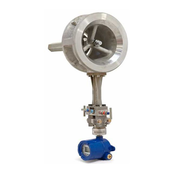
1. Rotating the electronics enclosure
Rotating the display
The electronics housing can be rotated through 360 degrees by releasing the 3 grub screws and turning the
white housing. The display can be rotated through +/-180 degrees. Do not rotate more then 360 degrees.
To rotate the electronics display, first disconnect the power supply to the MVT10. Unscrew the front
housing screw cap (with glass). Unscrew the three display retaining screws and rotate the complete display
cassette to the required position. Refit the retaining screws and front housing screw cap.
Fig. 1
IM-P337-73 EMM Issue 2
ILVA20 and MVT10 System
Essential Installation Guide
Instructions (IM-P337-69) supplied with product.
product performs to user expectations.
The ILVA20 and MVT10 are a calibrated pair.
Fixing screws
ILVA20 and MVT10 system
Caution:
Do not unplug the cables from the display
cassette and ensure that the cables are not
strained or trapped whilst carrying out this
procedure.
Caution:
Electrostatic
discharge
should be followed whilst rotating the display.
IM-P337-73
EMM Issue 2
(ESD)
procedures
© Copyright 2021
© Copyright 2019
1
Printed in GB
Printed in GB
Advertisement
Table of Contents

Subscribe to Our Youtube Channel
Related Manuals for Spirax Sarco ILVA20


Summary of Contents for Spirax Sarco ILVA20
- Page 1 This guide highlights the minimum installation requirements to ensure that the product performs to user expectations. The ILVA20 and MVT10 are a calibrated pair. Ensure the correct MVT10 is fitted to the correct ILVA20. 1. Rotating the electronics enclosure Rotating the display The electronics housing can be rotated through 360 degrees by releasing the 3 grub screws and turning the white housing.
- Page 2 Maximum 45º Fig. 2 The ILVA20 can be rotated in a horizontal line by up to 45° (downwards only), see above. The filling and hose connector plugs are supplied loose and thus need to be fitted to suit the orientation of the 2 way manifold.
- Page 3 Power (max 28 Vdc) R≥ 10K Ohm Loop powered 4-20 mA active display unit, 0 Volts chart recorder or current measuring DAQ device Fuse Power (+) In (-) +24 Vdc =/-10% Fig. 4 ILVA20 and MVT10 system IM-P337-73 EMM Issue 2...
- Page 4 3.2 EIA/TIA-485 communication wiring SLAVE 20FF WIRE LINKS TEMPERATURE PRESSURE DO NOT USE DO NOT USE +24Vdc +/-10% 250mA (min) EARTH* COMMON EARTH* EARTH* MASTER SLAVE SLAVE SLAVE Fig. 5 ILVA20 and MVT10 system IM-P337-73 EMM Issue 2...
Need help?
Do you have a question about the ILVA20 and is the answer not in the manual?
Questions and answers