Table of Contents
Advertisement
Quick Links
IM-P198-05
1987050/2
MI Issue 2
RIM20
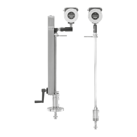
Rotor Insertion Flowmeter
Installation and Maintenance Instructions
1. Safety information
2. Introduction
3. Installation
4. Operating instructions
5. Serial communications
6. Troubleshooting and
repair
7. Appendixes
© Copyright 2016
IM-P198-05 MI Issue 2
1
Printed in GB
Advertisement
Table of Contents
Troubleshooting

Subscribe to Our Youtube Channel
Related Manuals for Spirax Sarco RIM20


Summary of Contents for Spirax Sarco RIM20
- Page 1 IM-P198-05 1987050/2 MI Issue 2 RIM20 Rotor Insertion Flowmeter Installation and Maintenance Instructions 1. Safety information 2. Introduction 3. Installation 4. Operating instructions 5. Serial communications 6. Troubleshooting and repair 7. Appendixes © Copyright 2016 IM-P198-05 MI Issue 2 Printed in GB...
- Page 2 Customer Notice for Oxygen Service This flowmeter is not intended for oxygen service. Spirax Sarco Limited is not liable for any damage or personal injury, whatsoever, resulting from the use of Spirax Sarco Rotor Insertion Flowmeters for oxygen gas. If oxygen service is required please consult factory.
- Page 3 3. Installation Installation overview Flowmeter installation requirements Unobstructed flow requirements Insertion flowmeter installation Cold tap guidelines Hot tap guidelines Flowmeter insertion Installing flowmeters with a compression connection Installing flowmeters with a packing gland connection 3.10 Installing flowmeters (Packing gland), no insertion tool 3.11 Display/Keypad adjustment 3.12...
- Page 4 4. Operating instructions Flowmeter display/keypad Start-up Using the setup menus Programming the flowmeter Output menu Display menu Alarms menu Totalizer #1 menu Totalizer #2 menu 4.10 Energy menu 4.11 Fluid menu 4.12 Units menu 4.13 Time and date menu 4.14 Diagnostics menu 4.15 Calibration menu...
- Page 5 6. Troubleshooting and repair Hidden diagnostics menus Level one hidden diagnostics values Level two hidden diagnostics values Analogue output calibration Troubleshooting the flowmeter First check items Record values Determine the fault Electronics assembly replacement 6.10 Returning equipment to the factory 7.
-
Page 6: Safety Information
Contact Spirax Sarco Customer Support between 8:00 a.m. and 5:00 p.m. When calling Technical Support, have the following information on hand: • the serial number and Spirax Sarco order number (all marked on the meter nameplate) • the problem you are encountering and any corrective action taken •... - Page 7 All flowmeter connections, isolation valves and fittings for cold/hot tapping must have the same or higher pressure rating as the main pipeline. For RIM20 rotor Insertion flowmeter installations, an Insertion tool must be used for any installation where a flowmeter is inserted under pressure greater than 3.45 bar g (50 psi g).
-
Page 8: Volumetric Flowmeters
2.1 RIM20 rotor insertion flowmeters The Spirax Sarco RIM20 rotor insertion flowmeters provide a reliable solution for process flow measurement. From a single entry point in the pipeline, RIM20 flowmeters offer precise measurements of mass or volumetric flowrates. 2.2 Multi-variable mass flowmeters... -
Page 9: Velocity Measurement
2.4 How the RIM20 rotor insertion flowmeter operates The RIM20 rotor insertion flowmeters are designed to monitor mass flowrate by directly measuring three variables-fluid velocity, temperature and pressure. The built-in flow computer calculates the mass flowrate and volumetric flowrate based on these three direct measurements. -
Page 10: Pressure Measurement
2.11 Line size / process connections The RIM20 rotor insertion flowmeter can be used in line sizes DN50 (2") and greater and is built with a compression fitting or packing gland design using 50 mm (2") NPT, or DN50 (2") flanged connections (ANSI 150, 300, 600, PN16, 40, or 63 class flanges). -
Page 11: Flowmeter Electronics
A pulse output signal for remote totalization and MODBUS, BACnet or HART communications are also available. RIM20 flowmeters include a local 2 x 16 character LCD display housed within the enclosure. Local operation and reconfiguration is accomplished using six pushbuttons operated via finger touch. -
Page 12: Installation Overview
3. Installation 3.1 Installation overview The RIM20 rotor insertion flowmeter installations are simple and straightforward. After reviewing the installation requirements given below, see Section 3.4 for RIM20 installation instructions. Warning! Consult the flowmeter nameplate for specific flowmeter approvals before any hazardous location installation. - Page 13 Example 6 : If the regulator or valve Example 3 : Two 90º elbow before is partially closed before the RIM20 the RIM20 flowmeter out of plane (if flowmeter (If the valve is always there are three 90º bends present,...
- Page 14 3.4.2 Isolation valve selection An isolation valve is available as an option with RIM20 flowmeters. If you supply the isolation valve, it must meet the following requirements: 1. A minimum valve bore diameter of 47.625 mm (1.875") is required, and the valve's body size should be DN50 (2").
-
Page 15: Cold Tap Guidelines
3.5 Cold tap guidelines Refer to a standard code for all pipe tapping operations. The following tapping instructions are general in nature and intended for guideline purposes only. Caution! When using toxic or corrosive gases, purge the line with inert gas for a minimum of four hours at full gas flow before installing the flowmeter. -
Page 16: Hot Tap Guidelines
3.6 Hot tap guidelines Refer to a standard code for all pipe tapping operations. The following tapping instructions are general in nature and intended for guideline purposes only. Warning! Hot tapping must be performed by a trained professional. US. regulations often require a hot tap permit. - Page 17 Check upstream and downstream requirements Weld mounting adapter Connect process connection (flange or NPT) Connect isolation valve and test for leaks Hot tap pipe Purge pipe Connect meter to valve, calculate insertion depth, install flowmeter Fig. 5 Hot tap sequence IM-P198-05 MI Issue 2...
-
Page 18: Flowmeter Insertion
3.7 Flowmeter Insertion The sensor head must be properly positioned in the pipe. For this reason, it is important that insertion length calculations are carefully followed. A sensor probe inserted at the wrong depth in the pipe will result in inaccurate readings. insertion flowmeters are applicable to pipes DN50 (2") and larger. -
Page 19: Installing Flowmeters With A Compression Connection
Fig. 6 Insertion calculation (compression type) Example: To install a RIM20 meter with a standard probe (S = 728.218 mm (28.67")) into a DN350 (14") schedule 40 pipe, the following measurements are taken: F = 76.2 mm (3") R = 127 mm (5") t = 11.125 mm (0.438") The insertion length for this example is 513.842 mm (20.23"). - Page 20 3.8.1 Insertion procedure for meters with a compression connection Sensor alignment pointer Enclosure adapter Stem Compression nut Stem housing Compression nut Stem housing Sensor head 2" NPT connection Flange connection Fig. 7 Flowmeter with compression type fitting Caution! The sensor alignment pointer must point downstream, in the direction of flow. Warning! To avoid serious injury, DO NOT loosen the compression fitting under pressure.
-
Page 21: Installing Flowmeters With A Packing Gland Connection
Fig. 8 Insertion calculation (Meters with insertion tool) Example 1: Flange Style Meters: To install a RIM20 flowmeter into a DN350 (14") schedule 40 pipe, the following measurements are taken: F = 304.8 mm (12") R = 127 mm (5") t = 11.125 mm (0.438") The example insertion length is 408.686 mm (16.09"). -
Page 22: Insertion Procedure For Flowmeters With Permanent Insertion Tool
3.9.1 Insertion procedure for flowmeters with permanent Insertion tool Upper retractor bracket Depth marker arrow EX IT ENTER Stanchion Stem lock bolt (center) Scribe mark Sensor alignment pointer Stem Packing gland nuts Stem housing Permanent insertion tool Fig. 9 Flowmeter with permanent insertion tool Sensor head Flow... - Page 23 Caution! The sensor alignment pointer must point downstream, in the direction of flow. Note If line pressure is above 34.47 bar g (500 psi g), it could require up to 33.895 N-m (25 ft lb) of torque to insert the flowmeter. Do not confuse this with possible interference in the pipe.
-
Page 24: Insertion Procedure For Flowmeters With Removable Insertion Tool
3.9.2 Insertion procedure for flowmeters with removable insertion tool Upper retractor bracket Depth marker arrow Stanchion Stem lock bolt (center) Scribe mark Sensor alignment pointer Stem Stem clamp nuts Stem clamp bolts Packing gland nuts (covered by stem clamp) Lower retractor bracket Removable insertion tool Stem housing Fig. - Page 25 Caution! The sensor alignment pointer must point downstream, in the direction of flow. Note If line pressure is above 34.473 bar g (500 psi g), it could require up to 33.895 N-m (25 ft lb) of torque to insert the flowmeter. Do not confuse this with possible interference in the pipe.
- Page 26 Fig. 11 Insertion calculation (Meters without insertion tool) Example: To install a RIM20 flowmeter with a standard probe (S = 728.218 mm (28.67")) into a DN350 (14") schedule 40 pipe, the following measurements are taken: F = 76.2 mm (3") R = 127 mm (5") t = 11.125 mm (0.438") The example insertion length is 513.842 mm (20.23").
- Page 27 3.10.1 Insertion procedure for flowmeters with no insertion tool (Packing gland connection) Warning! The line pressure must be less than 3.48 bar g (50 psi g) for installation. Caution! The sensor alignment pointer must point downstream, in the direction of flow. 1.
-
Page 28: Display / Keypad Adjustment (All Meters)
3.11 Display / Keypad adjustment (All meters) The orientation of the display / keypad may be changed in 90 degree increments for easier viewing. Rotate display / keypad in 90 degrees increments (maximum 180 degrees from original position) Fig. 12 Display / keypad viewing adjustment The electronics boards are electro-statically sensitive. -
Page 29: Loop Power Flowmeter Wiring Connections
3.12 Loop power flowmeter wiring connections Warning! To avoid potential electric shock, follow National Electric Code safety practices or your local code when wiring this unit to a power source and to peripheral devices. Failure to do so could result in injury or death. All wiring procedures must be performed with the power off. -
Page 30: Input Power Connections
Fig. 14 dc power connections 3.14 4-20 mA output connections The RIM20 flowmeter has a single 4-20 mA loop. The 4-20 mA loop current is controlled by the meter electronics. The electronics must be wired in series with the sense resistor or current meter. -
Page 31: Pulse Output Connections
3.15 Pulse output connections The pulse output is used for a remote counter. When the preset volume or mass (defined in the totalizer settings, see Section 4) has passed the meter, the output provides a 50 millisecond square pulse. The pulse output requires a separate 5 to 36 Vdc power supply. The pulse output optical relay is a normally-open single-pole relay. -
Page 32: Frequency Output Connections
3.16 Frequency output connections The frequency output is used for a remote counter. It can be scaled to output a 1 to 10 kHz signal proportional to mass or volume flow, temperature, pressure or density. The frequency output requires a separate 5 to 36 Vdc power supply; however, there are current and power specifications that must be observed. -
Page 33: Remote Electronics Wiring
3.18 Remote electronics wiring The remote electronics enclosure should be mounted in a convenient, easy to reach location. For hazardous location installations, make sure to observe agency requirements for installation. Allow some slack in the interface cable between the junction box and the remote electronics enclosure. -
Page 34: High Power Flowmeter Wiring Connections
3.19 High power flowmeter wiring connections Warning! To avoid potential electric shock, follow National Electric Code safety practices or your local code when wiring this unit to a power source and to peripheral devices. Failure to do so could result in injury or death. All ac power connections must be in accordance with published CE directives. -
Page 35: Ac Power Wiring
3.20 Input power connections Caution! The ac wire insulation temperature rating must meet or exceed 85 °C (185 °F). To access the wiring terminal blocks, locate and loosen the small set screw which locks the small enclosure cover in place. Unscrew the cover to expose the terminal block. 3.20.1 ac power wiring The ac power wire size must be 20 to 10 AWG with the wire stripped 7 mm (¼"). -
Page 36: Dc Power Wiring
3.20.2 dc power wiring Caution! The dc wire insulation temperature rating must meet or exceed 85 °C (185 °F). The dc power wire size must be 20 to 10 AWG with the wire stripped 7 mm (¼"). Connect 18 to 36 Vdc (300 mA, 9 W maximum) to the +dc Pwr and -dc Pwr terminals on the terminal block. - Page 37 3.21 4-20 mA output connections The standard RIM20 flowmeter has a single 4-20 mA loop. Two additional loops are available on the optional communication board. The 4-20 mA loop current is controlled by the meter electronics. The electronics must be wired in series with the sense resistor or current meter.
- Page 38 dc powered flowmeters only mA meter For HART For HART ® communications communications the signal loop + 24 Vdc 4-20 mA + the signal loop must have a must have a - 24 Vdc 4-20 mA - minimum of minimum of 250 ohms load 250 ohms load resistance.
- Page 39 R current limit - 10 k R current limit - 10 k Pulse voltage = +V Pulse voltage = +V Freq. Out + Freq. Out + Select resistor so that current Select resistor so that current Freq. Out - Freq. Out - through pulse ...
- Page 40 3.23 Pulse output connections The pulse output is used for a remote counter. When the preset volume or mass (defined in the totalizer settings, see Section 4) has passed the meter, the output provides a 50 millisecond square pulse. The pulse output optical relay is a normally-open single-pole relay. The relay has a nominal 200 volt/160 ohm rating.
- Page 41 R current limit - 10 k R current limit - 10K Pulse voltage = +V Pulse voltage = +V Pulse + Pulse + Select resistor so that current Select resistor so that current Pulse - Pulse - through pulse 40 mA through pulse ...
-
Page 42: Alarm Output Connections
3.24 Alarm output connections One alarm output (Alarm 1) is included on the standard RIM20 flowmeter. Two or more alarms (Alarm 2 and Alarm 3) are included on the optional communication board. The alarm output optical relays are normally- open single-pole relays. The relays have a nominal 200 volt/160 ohm rating. - Page 43 R current limit - 10 k R current limit - 10K Pulse voltage = +V Pulse voltage = +V Alarm + Alarm + Select resistor so that current Select resistor so that current Alarm - Alarm - through pulse 40 mA through pulse ...
-
Page 44: Optional Input Electronics Wiring
3.25 Remote electronics wiring The remote electronics enclosure should be mounted in a convenient, easy to reach location. For hazardous location installations, make sure to observe agency requirements for installation. Allow some slack in the interface cable between the junction box and the remote electronics enclosure. -
Page 45: Optional Energy Ems Rtd Input Wiring
3.27 Optional Energy EMS RTD Input Wiring Option 1 Option 2 1 2 3 4 5 1 2 3 4 5 Red Red Black Black R = 1000 Ohm Fig. 42 Optional energy EMS RTD input wiring The recommended customer supplied second RTD is a Class A 1000 ohm 4-wire platinum RTD. -
Page 46: Optional External Contact Closure Input Wiring
Option 1 Option 2 Option 1 Option 2 " " 1 2 3 4 5 1 2 3 4 5 d c powered meter only. dc powered meter only Fig. 44 dc power + d c PWR + dc Pwr dc power External 4-20 mA dc common... -
Page 47: Flowmeter Display/Keypad
4. Operating instructions After installing the RIM20 rotor insertion flowmeter, you are ready to begin operation. The sections in this Section explain the display/keypad commands, meter start-up and programming. The meter is ready to operate at start up without any special programming. - Page 48 4.2 Start-up Note Starting the flowmeter or pressing EXIT will always display the Run mode screens. To begin flowmeter operation: 1. Verify the flowmeter is installed and wired as described in Section 3. 2. Apply power to the meter. At start up, the unit runs a series of selftests that check the RAM, ROM, EPROM and all flow sensing components.
-
Page 49: Run Mode Screens
Run mode screens Press Exit to return to Run mode Use keys to access each item IM-P198-05 MI Issue 2... - Page 50 4.3 Using the set-up menus Run mode screens IM-P198-05 MI Issue 2...
-
Page 51: Setup Menus
3. Use the Setup Menus described on the following pages to customize the multiparameter features of your RIM20 flowmeter. (The entire lower display line is available for entering parameters.) Some items depicted in the graphic on the preceding page may not be displayed based on flowmeter configuration settings 4. -
Page 52: Output Menu
4.5 Output menu IM-P198-05 MI Issue 2... - Page 53 Example for setting an output The following shows how to set Output 1 to measure mass flow with 4 mA = 0 lb/hr and 20 mA = 100 lb/hr with a time constant of 5 seconds. (All outputs are disabled while using the Setup Menus.) First, set the desired units of measurement: 1.
-
Page 54: Display Menu
4.6 Display menu Run Mode ENTER Password ENTER Display Menu keys to access menus Cycle Time (sec) If Cycle Time is set to zero, manual advance is required Number of Digits Used to set the number of digits displayed after the decimal point Display TC (sec) TC = Display Time constant, used to smooth display MF Vf Te Pr De T... - Page 55 Example for changing a run mode display item The following shows how to remove the temperature screen from the Run mode screens. Note: all outputs are disabled while using the Setup Menus. 1. Use ïð keys to move to the Display Menu. 2.
-
Page 56: Alarms Menu
4.7 Alarms menu Energy EM meters only IM-P198-05 MI Issue 2... - Page 57 Example for setting an alarm The following shows how to set Relay Alarm 1 to activate if the mass flowrate is greater than 100 lb/hr. You can check the alarm configuration in the Run mode by pressing the keys until Alarm [1] appears.
- Page 58 4.8 Totalizer #1 menu Use the Totalizer Menu to configure and monitor the totalizer. The totalizer output is a 50 millisecond (.05 second) positive pulse (relay closed for 50 milliseconds). The totalizer cannot operate faster than one pulse every 100 millisecond (0.1 second). A good rule to follow is to set the unit per pulse value equal to the maximum flow in the same units per second.
- Page 59 Example for setting an alarm The following shows how to set the totalizer to track mass flow in kg/sec. (All outputs are disabled while using the Setup Menus.) First, set the desired units of measurement: 1. Use ïð keys to move to the Units Menu. 2.
- Page 60 4.9 Totalizer #2 menu Use the Totalizer #2 to Monitor Flow or Energy. Note that Totalizer #2 does not operate a relay, it is Use the Totalizer #2 to Monitor Flow or Energy.
- Page 61 4.10 Energy menu - For EM energy meters only Configuration: There are several possibilities regarding the measurement of water or steam energy given the location of the meter and the use of a second RTD. The table below summarizes the possibilities: Fluid Meter location...
-
Page 62: Fluid Menu
4.11 Fluid menu ENTER Run Mode Password ENTER Fluid Menu keys to access menus < Liquid Water Ammonia Chlorine Flowing Fluid Liquids > < Density > Other Liquids > xxxx Goyal-Dorais > API 2540 > < Mole Weight > Nat Gas AGA8 > xxxx Real Gas >... - Page 63 Use the Fluid Menu to configure the flowmeter for use with common gases, liquids and steam. Your flowmeter is pre-programmed at the factory for your application’s process fluid. Reference Richard W. Miller, Flow Measurement Engineering Handbook (Third Edition, 1996), for definition and use of the Goyal-Doraiswamy equation and for the definition and use of the API 2540 equation.
-
Page 64: Units Menu
4.12 Units menu Use the Units Menu to configure the flowmeter with the desired units of measurement. (These are global settings and determine what appears on all screens. IM-P198-05 MI Issue 2... -
Page 65: Time And Date Menu
4.13 Time and date menu Use the Time and Date Menu to enter the correct time and date into the flowmeter’s memory. The parameters are used in the Run mode and the alarm and system log files. Note: Time is displayed in AM/PM format, but military format is used to set the time. For example, 1:00 PM is entered as 13:00:00 in the Set Time menu. -
Page 66: Diagnostics Menu
4.14 Diagnostics menu IM-P198-05 MI Issue 2... - Page 67 Use the Diagnostics Menu to simulate operation and review the system files. The system log files contain time/date stamped messages including: power on, power off, programming time outs, parameter faults, incorrect password entry and other various information relative to system operation and programming. The simulated inputs are for testing the meter to verify that the programming is correct.
-
Page 68: Calibration Menu
4.15 Calibration menu ENTER Run Mode Password ENTER Calibration Menu keys to access menus Pipe ID xx.xxxx Meter Factor xxxx < Vol (xxx/xxx) > < Mass (xxx/xxx) > Low Flow Cutoff Low Flow Cutoff Low Flow Cutoff setting displayed setting displayed in volumetric flow in mass flow Serial Number... -
Page 69: Password Menu
4.16 Password menu Use the Password Menu to set or change the system password. The factory-set password is 1234. IM-P198-05 MI Issue 2... -
Page 70: Serial Communications
5. Serial communications 5.1 HART communications The HART Communications Protocol (Highway Addressable Remote Transducer Protocol) is a bidirectional digital serial communications protocol. The HART signal is based on the Bell 202 standard and is superimposed on 4-20 mA Output 1. Peer-to-peer (Analogue / digital) and multi-drop (digital only) modes are supported. -
Page 71: Dc Powered Meter Wiring
Turbine Meter 5.2.2 dc Powered Meter Wiring R S 485 R S 485 R S 485 G ND Turbine R load, Current Turbine Meter Power 250 ohm meter Fig. 49 dc powered meter wiring (HART) Meter Supply minimum R S 485 R S 485 R load, R S 485 G ND... -
Page 72: Hart Commands With The Dd Menu
5.3 HART Commands with the DD menu 5.3.1 Online Menu 1 Device Setup 1 K Factor 2 Ck Value 3 Lo Flo Cutoff 4 RTD1 Ro 5 RTD1 alpha 6 RTD1 beta 7 RTD2 Ro 8 RTD2 alpha 9 RTD2 beta Pcal B00, Pcal B01 Pcal B02, Pcal B10 Pcal B11, Pcal B12... - Page 73 1 Display Unit 1 Mass flo unit 2 Vol unit 3 Temp unit 4 Energy flo unit 5 Line press unit 1 Norm Temp 6 Dens unit 2 Norm Press 7 Totalizer units 3 Std Temp 8 Std & Norm Cond 4 Std Press 2 Analog Output To Analog Output Menu...
- Page 74 5.3.2 Analogue output menu 1 Fix Analog Output 2 Trim Analog Output From Online Menu 1 PV is 3 Configure AO1 2 PV AO1 Out 4 PV is 3 PV 5 PV AO1 Out 4 PV % rnge 6 PV % rnge 5 Apply values 7 Configure AO2 6 PV Rnge unit...
- Page 75 5.3.3 Fluid menu From Online Menu 1 Fluid Liquid Water 2 Fluid Type Other Liquid Ammonia Goyal-Dorais Chlorine API-2540 Nat Gas AGA8 Real Gas Other Liquid Density Other Gas Viscosity Coef AL Liquified Gas Viscosity Coef BL Mol Weight Crit Press Crit Temp Compressibility Density @ 60F...
- Page 76 1 Turbine Diag 1 Tbn Freq From Online Menu 2 Press Diag 2 Sim Tbn Freq 5.3.4 Diagnostics menu 3 Temp Diag 3 Tbn AtoD 4 Vel 4 Filter Set 5 Temp 5 Gain Set 1 Turbine Diag 1 Tbn Freq From Online Menu 6 Temp 2 6 Re...
-
Page 77: Sensor Cal Menu
5.3.6 Sensor cal menu To Calibration Review Menu 1 Calibration Review From Online Menu 1 Vol snsr unit 1 Tbn Freq 2 Turbine Sensor 2 USL 2 Sim Tbn Freq 3 Turbine Cal 3 LSL 3 Tbn AtoD 4 Press Sensor 4 Min Span 4 Filter Set 5 Press Cal... -
Page 78: Hart Commands With Generic Dd Menu
5.4 HART commands with generic DD menu Online Menu 1 Device Setup 1 Process Variables 1 Snsr 1 4 mA 2 PV 2 AI % Rnge 2 20 mA 3 PV AO 3 AO1 3 Other 1 4 mA 4 End 2 20 mA 1 Test Device 3 Exit... - Page 79 1 PV 1 Sensors PV LSL, PV USL, PV Min span 2 PV Sensor Unit 3 Sensor information 1 Snsr Damp 2 URV 1 PV LRV 2 Signal Condition 3 AI LRV 2 PV URV 4 Xfer Fnctn 5 AI % rnge 1 AO1 1 4 mA 2 AO alarm typ...
-
Page 80: Fast Key Sequence
5.4.1 Fast key sequence Use password 16363. Sequence Description Access Notes 1,1,1 Snsr View Primary variable value 1,1,2 AI % Rnge View Analogue output % range 1,1,3 View Analogue output, mA 1,2,1 Test Device Not used 1,2,2,1 4 mA View Loop test, fix Analogue output at 4 mA 1,2,2,2 20 mA... - Page 81 Sequence Description Access Notes 1,4,1,1 View Primary variable value 1,4,1,2 PV Sensor Unit Edit Primary variable units 1,4,1,3 Sensor Information View PV LSL, PV USL, PV Min span Primary variable damping (time constant) 1,4,2,1 Snsr Damp Edit in seconds 1,4,2,2,1 PV LRV Edit Primary variable low range value...
-
Page 82: Modbus Communications
5.5.2 Overview This document describes the preliminary implementation of the Modbus communication protocol for use in monitoring common process variables in the Spirax Sarco RIM20 rotor insertion flowmeter. The physical layer utilizes the half-duplex RS-485 port, and the Modbus protocol. - Page 83 5.5.6 Menu Items The following menu items are in the Output Menu and allow selection and control of the Modbus communication protocol. 5.5.7 Address When the Modbus protocol is selected, the Modbus address is equal to the user programmable device address if it is in the range 1…247, in accordance with the Modbus specification. If the device address is zero or is greater than 247, then the Modbus address is internally set to 1.
-
Page 84: Modbus Protocol
5.5.12 Modbus protocol The Modbus RTU protocol is supported in this implementation. Supported baud rates are 1200, 2400, 4800, 9600, 19200, 38400, 57600, and 115200. The default baud rate is 19200 baud. Depending upon the Modbus protocol selected, data are transmitted in 8-bit data frames with even or odd parity and 1 stop bit, or no parity and 2 or 1 (non-standard) stop bits. -
Page 85: Register Definitions
5.6 Register definitions The meter serial number and those variables that are commonly monitored (mass, volume and energy flowrates, total, pressure, temperature, density, viscosity, Reynolds number, and diagnostic variables such as frequency, velocity, gain, amplitude and filter setting) are accessible via the Modbus protocol. Long integer and floating point numbers are accessed as pairs of 16-bit registers in the register order selected in the Modbus Order menu. - Page 86 Table 3 Register Definitions The following registers are available with the energy meter firmware: Function Registers Variable Data type Units Addresses code display 30527-30528 Totalizer #2 unsigned long 03, 04 526-527 units* 32043-32048 Totalizer #2 units string — 03, 04 2042-2047 display 30003-30004...
-
Page 87: Exception Status Definitions
5.6.1 Exception status definitions The Read Exception Status command (function code 07) returns the exception status byte, which is defined as follows. This byte may be cleared by setting"coil" register #00003 (function code 5, address 2, data = 0xff00). Bit(s) Definition Byte order (see Modbus Order on page 2) 0 = 3-2:1-0 1 = 2-3:0-1... - Page 88 5.6.4 Error responses If an error is detected in the message received by the unit, the function code in the response is the received function code with the most significant bit set, and the data field will contain the exception code byte, as follows: Exception Code Description Invalid function code —...
- Page 89 5.6.8 Examples Read the exception status byte from the device with address 1: 01 07 41 E2 01 Device address 07 Function code, 04 = read exception status A typical response from the device is as follows: 01 07 03 62 31 01 Device address 07 Function code 03 Exception status byte...
- Page 90 results in an error response as follows: 01 84 02 C2 C1 01 Device address 84 Function code with most significant bit set indicates error response 02 Exception code 2 = invalid data address C2 C1 CRC Request the state all three alarms: 01 02 00 00 00 03 38 0B 01 Device address 02 Function code 2 = read discrete inputs...
-
Page 91: Bacnet Ms/Tp Communications
The baud rate setting determines the rate at which devices communicate data over the bus. The baud rate settings available on RIM20 Vortex Mass flowmeters are 9600, 19200, 38400, 57600 and 115200 5.8.1 Baud Rate and MAC address configuration... -
Page 92: Supported Bacnet Objects
5.9 Supported BACnet objects A BACnet object represents physical or virtual equipment information, as a digital input or parameters. The RIM20 Vortex Mass flowmeters presents the following object types: a. Device Object b. Analogue Input c. Binary Input d. Binary Value Each object type defines a data structure composed by properties that allow the access to the object information. - Page 93 Properties Object Types Device Analogue Binary Binary input input value Max_Masters Max_Info_Frames Device_Address_Binding Database_Revision Status_Flags Event_State Reliability Out_Of_Service (W) (W) (W) Units Polarity (W) Priority_Array Relinquish_Default Status_Flag ...
-
Page 94: Device Object
(Analogue-input,5), (Analogue-input,14), (binaryinput, 3), (Analogue-input,6), (Analogueinput, 15), (binary-input,4), (Analogue-input,7), (Analogue-input,16), (binary-value,1), (Analogue-input,8) (Analogue-input,17), (device,7) } (Analogue-input,9), max-apdu-length-accepted 300 segmentation-supported no-segmentation apdu-timeout 3000 number-of-APDU-retries max-master max-info-frames device-address-binding database-revision Note - Device Communication Control: Password -"Spirax Sarco" IM-P198-05 MI Issue 2... - Page 95 5.9.2 Analogue input object: Vortex Mass flowmeters Analogue Input type objects are described in the below Table - Object Object name Unit Description instance cubic-feet-per-second, cubic-feet-per-minute, us-gallons-per-minute, imperial-gallons-per- minute, This AI object is used litres-per-minute, Volume flow to measure volume litres-per-second, flow.
- Page 96 Object Object name Unit Description instance If Totalizer selection for Mass measure - pounds-mass-per-second, grams-per-second, kilograms-per-second , kilograms-per-minute , kilograms-per-hour, pounds-mass-per-minute , pounds-mass-per-hour, tons-per-hour, grams-per-second , grams-per-minute An electronic counter If Totalizer selection for Volume Totalizer 1 which records the total measure - cubic-feet-per-second, &...
-
Page 97: Binary Input Object
5.9.3 Binary input object: Vortex Mass flowmeters Binary Input type objects are described in the below Table. Object instance Object name Description Alarm1 The status of the three alarms may be monitored via the Modbus command. The value returned indicates Alarm2 the state of the alarm, and will be 1 only if the alarm is enabled and active. -
Page 98: Annex - Bacnet Protocol Implementation Conformance Statement
5.10 ANNEX - BACnet protocol implementation conformance statement Date: 19-April-2012 Applications Software Version: 1.07 Firmware Revision: N/A BACnet Protocol Revision: 4 BACnet Standardized Device Profile (Annex L): BACnet Operator Workstation (B-OWS) BACnet Advanced Operator Workstation (B-AWS) BACnet Operator Display (B-OD) ... -
Page 99: Segmentation Capability
5.10.2 Segmentation capability: Able to transmit segmented messages - Window Size Able to receive segmented messages - Window Size 5.10.3 Standard object types supported Standard object types supported Object type Dynamically Dynamically Additional Range creatable deleteable writable restrictions properties Analogue Input (AI) None... -
Page 100: Object List
5.10.4 Object list Properties of Analogue Input/Value Objects Type Present Status Event Out of Name Units value flags state service Volume Flow F,F,F,F Normal False Mass Flow F,F,F,F Normal False Temperature 1 F,F,F,F Normal False Temperature 2 F,F,F,F Normal False Pressure F,F,F,F Normal... - Page 101 Properties of Analogue Input/Value Objects Type Name Present Status Event Out of out-of-service value flags ftate fervice Reset F,F,F,F Normal False False 5.10.5 Data link layer options: BACnet IP, (Annex J) BACnet IP, (Annex J), Foreign Device ISO 8802-3, Ethernet (Clause 7) ...
-
Page 102: Troubleshooting And Repair
5.11 Acronyms and definitions Item Description APDU Application Protocol Data Unit BACnet Building Automation and Control Network- Data communication protocol MS/TP Master-Slave Token passing(a twisted pair RS485 network created by BACnet) BACnet Interoperability Building Block (Specific individual function blocks for BIBB data exchange between interoperable devices). - Page 103 Level one values Level two values 4-20(1), Zero Output Type Alarm(1) Test xxxx None 4-20(1), Fscale Alarm(2) Test Pulse Out Queue Calibration Mode xxxx xxxxxxxxxx 4-20(2), Zero Alarm(3) Test A2D Ref. Resistor xxxx 2700 Sig. Rev. Profile Factor 4-20(2), Fscale Pres Cal Current Reynolds Corr.
-
Page 104: Level One Hidden Diagnostics Values
6.2 Level one hidden diagnostics values Turbine frequency (Hz). Adaptive filter - should be approximately 25% higher than the turbine frequency, this is a low-pass filter. If the meter is using the Filter Control (see below) in the manual mode, fi will be displayed as fm. - Page 105 Threshold level. If the Low Flow Cutoff in the calibration menu is set above this value, the meter will read zero flow. The Lvl level can be checked at no flow. At no flow, the Lvl must be below the Low Flow Cutoff setting or the meter will have an output at no flow.
-
Page 106: Level Two Hidden Diagnostics Values
6.3 Level two hidden diagnostics values 4-20(1) Zero Analogue counts to calibrate zero on Analogue output 1. 4-20(1) FScale Analogue counts to cal. full scale on Analogue output 1. 4-20(2) Zero Analogue counts to calibrate zero on Analogue output 2. 4-20(2) FScale Analogue counts to cal. - Page 107 Reset factory defaults. If you change this to Yes and press Enter, all the factory configuration is lost and you must reconfigure the Factory Defaults entire program. Consult the factory before performing this process, it is required only in very rare cases. Config Code Factory use only.
-
Page 108: Troubleshooting The Flowmeter
6.4 Analogue output calibration To check the 4-20 mA circuit, connect a DVM in series with the output loop. Select zero or full scale (from the second column of the hidden diagnostics) and then actuate the enter key twice. This action will cause the meter to output its 4 mA or 20 mA conditions. If the DVM indicates a current greater than ±0.006 mA from 4 or 20, adjust the setting up or down until the output is calibrated. - Page 109 Record the following values from the Hidden Diagnostics Menu with the meter installed: (Use password 16363 to access.) With Flow With No Flow (if possible) fi = A1 = A2 = A3 = A4 = RTD1 = RTD2 = Pe(V) = Pv(V) = Ck = Lvl =...
-
Page 110: Determine The Fault
6.8 Determine the fault 6.8.1 Symptom: output at no flow 1. The low flow cutoff is set too low. At no flow, go to the first column of the hidden diagnostics menu and record the Lvl value. The low flow cutoff must be set above this value. 2. -
Page 111: Symptom: No Output
Turbine Pressure Turbine Temperature Pressure Temperature Fig. 53 Remote feed through board sensor connections 6.8.3 Symptom: no output 1. For remote mounted electronics, carefully check all the wiring connections in the remote mount junction box. There are 18 connections that must be correct, verify each color (black and red), shield, and wire number. -
Page 112: Symptom: Meter Displays Temperature Fault
6.8.4 Symptom: meter displays temperature fault 1. For remote mounted electronics, carefully check all the wiring connections in the remote mount junction box. There are 18 connections that must be correct, verify each color (black and red), shield, and wire number. 2. -
Page 113: Symptom: Meter Displays Pressure Fault
6.8.5 Symptom: meter displays pressure fault 1. For remote mounted electronics, carefully check all the wiring connections in the remote mount junction box. There are 18 connections that must be correct, verify each color (black and red), shield, and wire number. 2. -
Page 114: Electronics Assembly Replacement (All Meters)
8. Repeat steps 1 through 6 in reverse order to install the new electronics stack. 6.10 Returning equipment to the factory Before returning any RIM20 flowmeter to the factory, you must request a Return material Authorization (RMA) number. To obtain an RMA number and the correct shipping address, contact Customer Service at: When contacting Customer Service, be sure to have the meter serial number and model code. -
Page 115: Appendix A - Product Specifications
7. Appendixes 7.1 Appendix A - Product specifications Accuracy Process variables RIM20 rotor insertion flowmeters (1) Liquid, Gas & Steam Mass flowrate ±2% of rate(2) over a 30:1 range(3) Volumetric flowrate ±1.5% of rate over a 30:1 range(3) Temperature ±2 °F (±1 °C) Pressure 0.3% of transducer full scale... - Page 116 Typical Metric flowrates Saturated steam (kg / h) Nominal pipe size Rotor Pressure 80 mm 150 mm 200 mm 300 mm 400 mm 600 mm Minimum 1 219 1.4 bar g Maximum 1 642 3 817 6 270 15 367 Minimum 1 176 2 907...
- Page 117 Typical Metric flowrates Air (nm3 / h) at 20 °C Nominal pipe size Rotor Pressure 80 mm 150 mm 200 mm 300 mm 400 mm 600 mm Minimum 1.4 bar g Maximum 1 130 2 628 4 320 10 607 Minimum 1 259 2 072...
- Page 118 Typical Imperial flowrates Saturated steam (lb / h) Nominal pipe size Rotor Pressure 1DN50 3" 6" 8" 16" 24" (2") Minimum 1 555 5 psi g Maximum 1 187 2 098 4 883 8 029 19 727 Minimum 2 046 3 371 8 328 100 psi g...
- Page 119 Typical Imperial flowrates Air (SCFM) at 70 °F Nominal pipe size Rotor Pressure 1DN50 3" 6" 8" 16" 24" (2") Minimum 5 psi g Maximum 1 660 2 729 6 702 Minimum 1 051 1 730 4 257 100 psi g Maximum 3 252 5 741...
- Page 120 Linear range Fluid: Gas or steam Rotor Minimum velocity Maximum velocity m/sec ft/sec m/sec ft/sec 1.07 13.11 43.0 1.22 19.05 62.5 1.52 24.38 80.0 2.13 30.48 100.0 2.59 41.03 134.6 3.66 12.0 62.48 205.0 IM-P198-05 MI Issue 2...
- Page 121 Process fluid pressure RIM20 Pressure ratings Probe seal Process connection Material Rating 2" MNPT 316L SS ANSI 600 lb 2" 150 lb flange, DN50 PN16 316L SS ANSI 150 lb, PN16 Compression fitting 2" 300 lb flange, DN50 PN40 316L SS ANSI 300 lb, PN40 2"...
- Page 122 Pressure transducer ranges Pressure sensor ranges(1), bar a (psi a) Full scale operating pressure Maximum over-range pressure bar a psi a bar a psi a 1000 1500 2500 Note: (1) To maximize accuracy, specify the lowest full scale operating pressure range for the application.
- Page 123 Analogue: Volumetric Meter: field rangeable linear 4-20 mA output signal (1200 Ohms maximum loop resistance) selected by user for mass flowrate or volumetric flowrate. Communications: HART, MODBUS RTU, BACnet MS/TP Multiparameter Meter: up to three field rangeable linear 4-20 mA output Output signals (1200 Ohms maximum loop resistance) selected from the five signals (1)
-
Page 124: Low Voltage Directive
7.2 Appendix B Approvals Low Voltage Directive Directive 2014/35/EU EN 61010-1:2010 Electromagnetic Compatibility Directive Directive 2014/30/EU EN 61000-6-2:2005 EN 55011:2009 + A1:2010 Group 1 Class A IM-P198-05 MI Issue 2... - Page 125 7.3 Appendix C flowmeter calculations Flowing velocity Volume flowrate Mass flowrate A Where: = Cross sectional area of the pipe (ft = Turbine meter frequency (pulses / sec) = Meter factor corrected for Reynolds Number (pulses / ft) = Volume flowrate (ft / sec) = Mass flowrate (lbm / sec) = Flowing velocity (ft / sec)
-
Page 126: Fluid Calculations
Fluid calculations Calculations for Steam T & P When"Steam T & P" is selected in the"Real Gas" selection of the Fluid Menu, the calculations are based on the equations below. Density The density of steam is calculated from the formula given by Keenan and Keys. The given equation is for the volume of the steam. -
Page 127: Calculations For Gas ("Real Gas" And"Other Gas")
Calculations for Gas ("Real Gas" and"Other Gas") Use this formula to determine the settings for"Real Gas; Gas" selections and"Other Gas" selections entered in the Fluid Menu. The calculations for gas were taken from Richard W. Miller, Flow Measurement Engineering Handbook (Third Edition, 1996). Density The density for real gases is calculated from the equation: ... -
Page 128: Calculations For Liquid
Calculations for liquid Use this formula to determine the settings for"Goyal-Dorais" selections and"Other Liquid" selections entered in the Fluid Menu. The liquid calculations were taken from Richard W. Miller, Flow Measurement Engineering Handbook (Third Edition, 1996). Density The liquid density is found using the Goyal-Doraiswamy Equation. Goyal-Doraiswamy uses the critical compressibility, critical pressure and critical temperature, along with the molecular weight to find the density. -
Page 129: Appendix D Glossary
7.4 Appendix D Glossary Cross sectional area. ACFM Actual Cubic Feet Per Minute (volumetric flowrate). ASME American Society of Mechanical Engineers. British Thermal Unit, an energy measurement. Cenelec European Electrical Code. Compressibility A factor used to correct for the non-ideal changes in a fluid ís factor density due to changes in temperature and/or pressure. - Page 130 Insertion A flowmeter which is inserted into a hole in the us- erís pipeline. flowmeter A unit of energy equal to one watt for one second. Al- so equal Joule to a Newton-meter. Liquid crystal display. Mass flowrate. Milli-amp, one thousandth of an ampere of current. Viscosity, a measure of a fluidís resistance to shear stress.
- Page 131 Flowrate, usually volumetric. Highest measurable flowrate divided by the lowest measurable Rangeability flowrate. A dimensionless number equal to the density of a fluid or Retimes the velocity of the fluid times the diameter of the fluid channel, divided by the fluid viscosity (i.e., Re = rVD/m). The Reynolds Reynolds number number is an important num- ber for turbine flowmeters because it is used to determine the minimum measurable flowrate.
- Page 132 IM-P198-05 MI Issue 2...
Need help?
Do you have a question about the RIM20 and is the answer not in the manual?
Questions and answers