
Subscribe to Our Youtube Channel
Related Manuals for Spirax Sarco VLM30


Summary of Contents for Spirax Sarco VLM30
- Page 1 IM-P736-02 EMM Issue 3 VLM30 In-Line Vortex Flowmeter Installation and Maintenance Instructions VLM30 In-Line Vortex Flowmeter © Copyright 2023 IM-P736-02 EMM Issue 3...
- Page 2 VLM30 In-Line Vortex Flowmeter IM-P736-02 EMM Issue 3...
- Page 3 Customer Notice for Oxygen Service This flowmeter is not intended for oxygen service. Spirax Sarco Limited is not liable for any damage or personal injury, whatsoever, resulting from the use of Spirax Sarco Vortex Insertion and In-line flowmeters for oxygen gas.
-
Page 4: Table Of Contents
1.11 Permits to work 1.12 Handling 1.13 Residual hazards 1.14 Freezing 1.15 Returning products 1.16 Replacement parts 1.17 Disposal 1.18 Transport and Storage 2. General product information 2.1 How the Vortex Flowmeter Operates 2.2 Nameplate VLM30 In-Line Vortex Flowmeter IM-P736-02 EMM Issue 3... - Page 5 4.6 Checks after switching on the power supply 4.7 Checking and configuring the basic settings 4.8 Parameterisation via the menu function Easy Setup 4.9 Devices with HART and Modbus communication ® ® VLM30 In-Line Vortex Flowmeter IM-P736-02 EMM Issue 3...
- Page 6 7.7 Calling up the error description 7.8 Possible error messages 8. Repair 8.1 Replacing the transmitter, downloading system data 8.2 Removal from the line 9. Spares 10. Appendix 10.1 Measuring range tables 11. Approvals VLM30 In-Line Vortex Flowmeter IM-P736-02 EMM Issue 3...
-
Page 7: Safety Information
Caution! Calibration must be performed by qualified personnel. Spirax Sarco strongly recommends that you return your flowmeter to the factory for calibration. In order to achieve accurate and repeatable performance, the flowmeter must be installed with the specified minimum length of straight pipe upstream and downstream of the flowmeter’s sensor head. -
Page 8: Intended Use
Determine the correct installation situation and direction of fluid flow. iv) Spirax Sarco products are not intended to withstand external stresses that may be induced by any system to which they are fitted. It is the responsibility of the installer to consider these stresses and take adequate precautions to minimise them. -
Page 9: Hazardous Liquids Or Gases In The Pipeline
1.9 Tools and consumables Before starting work ensure that you have suitable tools and/or consumables available. Use only genuine Spirax Sarco replacement parts. 1.10 Protective clothing Consider whether you and/or others in the vicinity require any protective clothing to protect against the hazards of, for example, chemicals, high/low temperature, radiation, noise, falling objects, and dangers to eyes and face. -
Page 10: Residual Hazards
Customers and stockists are reminded that under EC Health, Safety and Environment Law, when returning products to Spirax Sarco they must provide information on any hazards and the precautions to be taken due to contamination residues or mechanical damage which may present a health, safety or environmental risk. -
Page 11: Transport And Storage
1.19 Food Contact This product is not to be used on steam, liquid or gas that either forms an ingredient of, or comes into direct contact with food products in the EU. VLM30 In-Line Vortex Flowmeter IM-P736-02 EMM Issue 3... - Page 12 Refer to Ambient conditions in Section 3.7. Returning devices For the return of devices, follow the instructions in Section 8.1 Replacing the transmitter, Section 8.2 Removal from the line, and Section 1.15 Returning products. VLM30 In-Line Vortex Flowmeter IM-P736-02 EMM Issue 3...
-
Page 13: General Product Information
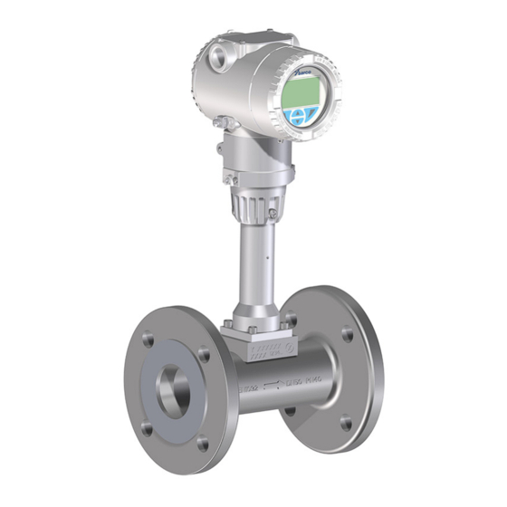
Integral mount design in Integral mount design flange design in wafer type design Fig. 1 VLM30 Variants VLM30 for steam, liquid and gas, with optional graphical display, optional binary output, and optional integrated temperature measurement. Remote mount design with transmitter... - Page 14 Unobstructed straight inlet section 15 × DN Outlet section 5 × DN Pressure measurement 3 × DN to 5 × DN behind the flowmeter High Temperature Version 'B2' expected Q4 2023. VLM30 In-Line Vortex Flowmeter IM-P736-02 EMM Issue 3...
- Page 15 (HART 7), Modbus RTU ® ® Power supply 12 to 42 Vdc Version dependent. VLM30-S can accept external HART inputs only. VLM30-E can accept external HART and external 4-20mA inputs. Please refer to section 3.18. VLM30 In-Line Vortex Flowmeter IM-P736-02 EMM Issue 3...
-
Page 16: How The Vortex Flowmeter Operates
If the bluff body is dimensioned appropriately, the Strouhal number (St) remains constant across a very wide range of the Reynolds number (Re). v x D Kinematic viscosity D Nominal diameter of meter tube VLM30 In-Line Vortex Flowmeter IM-P736-02 EMM Issue 3... - Page 17 The frequency signal from the flowmeter sensor, which is proportional to the flow, undergoes downstream processing in the transmitter. VLM30 In-Line Vortex Flowmeter IM-P736-02 EMM Issue 3...
-
Page 18: Nameplate
2.2 Nameplate Fig. 4(a) Name Plate Fig. 4(b) Additional Plate with Approvals (example shown) Fig. 4(c) Plate with measuring point tagging (Tag number) VLM30 In-Line Vortex Flowmeter IM-P736-02 EMM Issue 3... -
Page 19: Installation
The electronic components of the printed circuit board can be damaged by static electricity (observe ESD guidelines). Make sure that the static electricity in your body is discharged before touching electronic components. VLM30 In-Line Vortex Flowmeter IM-P736-02 EMM Issue 3... -
Page 20: Installation Conditions
The relationship between the measuring medium and the ambient temperature must be taken into consideration. At high measuring medium temperatures > 150 °C (> 302 °F), the sensor must be installed so that the transmitter or terminal box is pointing to the side or downward. VLM30 In-Line Vortex Flowmeter IM-P736-02 EMM Issue 3... -
Page 21: Inlet And Outlet Recommendations
Valve upstream of the meter tube minimum 50 x DN minimum 5 x DN Pipe reduction minimum 15 x DN minimum 5 x DN Pipe extension minimum 18 x DN minimum 5 x DN VLM30 In-Line Vortex Flowmeter IM-P736-02 EMM Issue 3... -
Page 22: Installation At High Measuring Medium Temperatures
At high measuring medium temperatures > 150 °C (> 302 °F), the sensor must be installed so that the transmitter is pointing to the side or downward. Fig. 7 Installation at high measuring medium temperatures VLM30 In-Line Vortex Flowmeter IM-P736-02 EMM Issue 3... -
Page 23: Installation For External Pressure And Temperature Measurement
If this is the case, it is essential that the valve be installed in the forward flow direction upstream from the flowmeter. Suitable dampers (for example, air vessels in the case of pumping using a compressor) might need to be used. VLM30 In-Line Vortex Flowmeter IM-P736-02 EMM Issue 3... -
Page 24: Sensor Insulation
If the maximum temperature the trace heating is able to produce is less than or equal to the maximum medium temperature. Note: Installation requirements in accordance with EN 60079-14 must be observed. Please note that the use of trace heaters will not impair EMC protection or generate additional vibrations. VLM30 In-Line Vortex Flowmeter IM-P736-02 EMM Issue 3... -
Page 25: Ambient Conditions
Temperature range high temperature version (option) -4/-40 (-40) 150 160 200 350 °C 302 320 392 662 °F medium Fig. 11 Measuring medium temperature T dependent on the ambient temperature T medium VLM30 In-Line Vortex Flowmeter IM-P736-02 EMM Issue 3... -
Page 26: Material Load
3.8 Material Load Flanged Devices 1740 PN100 1450 1160 PN63 PN40 PN25 PN16 PN10 350 (°C) 662 (°F) TS (°C/°F) Fig. 12(a) DIN Flange process connection VLM30 In-Line Vortex Flowmeter IM-P736-02 EMM Issue 3... - Page 27 3.8 Material Load (continued) Flanged Devices 1740 CL600 1450 1160 CL300 CL150 350 (°C) 662 (°F) TS (°C/°F) Fig. 12(b) ASME Flange process connection VLM30 In-Line Vortex Flowmeter IM-P736-02 EMM Issue 3...
- Page 28 120 150 180 210 240 270 300 330 (°C) 140 194 248 302 356 410 464 518 572 626 (°F) 350 (°C) 662 (°F) TS (°C/°F) Fig. 13(a) DIN Wafer type process connection VLM30 In-Line Vortex Flowmeter IM-P736-02 EMM Issue 3...
- Page 29 120 150 180 210 240 270 300 330 (°C) 140 194 248 302 356 410 464 518 572 626 (°F) 350 (°C) 662 (°F) TS (°C/°F) Fig. 13 (b) ASME Wafer type process connection VLM30 In-Line Vortex Flowmeter IM-P736-02 EMM Issue 3...
-
Page 30: Installing The Sensor
First tighten the nuts to approximately 50% of the maximum torque, then to approximately 80%, and finally a third time to the maximum torque. Note: Torques for screws depend on temperature, pressure, screw and gasket materials. The relevant applicable regulations must be taken into consideration. VLM30 In-Line Vortex Flowmeter IM-P736-02 EMM Issue 3... -
Page 31: Centering The Wafer Type Design
3.10 Centering the wafer type design Bolt Centering ring Meter tube (wafer type) Bolt Centering segment Meter tube (wafer type) Fig. 15 Centering the wafer type design with the ring or segment VLM30 In-Line Vortex Flowmeter IM-P736-02 EMM Issue 3... -
Page 32: Adjusting The Transmitter Position
Loosen the locking screw on the transmitter housing using a 4 mm Allen key. Rotate the transmitter housing in the direction required. Tighten the locking screw. Fig. 16 Rotating the transmitter housing VLM30 In-Line Vortex Flowmeter IM-P736-02 EMM Issue 3... -
Page 33: Rotating The Lcd Indicator
If the O-ring gasket is seated incorrectly or is damaged, this may have an adverse effect on the IP rating. Check that the O-ring gasket is properly seated when closing the housing cover. VLM30 In-Line Vortex Flowmeter IM-P736-02 EMM Issue 3... -
Page 34: Opening And Closing The Housing
The electrical connection may only be established by authorised specialist personnel and in accordance with the connection diagrams. The electrical connection information in this manual must be observed; otherwise, the IP rating may be adversely affected. Ground the measurement system according to requirements. VLM30 In-Line Vortex Flowmeter IM-P736-02 EMM Issue 3... -
Page 35: Signal Cables
Copper braid with approximately 85% coverage. Temperature range Application-dependent. Maximum signal cable length 30 m (98 ft) 3.15 Installing the connection cables Drip loop Drip loop Fig. 19 Laying the connection cable VLM30 In-Line Vortex Flowmeter IM-P736-02 EMM Issue 3... -
Page 36: Cable Glands
Loosen the screw terminal on the transmitter housing or on the housing of the VLM30. Insert the forked cable lug for functional grounding between the two metal tabs and into the loosened terminal. -
Page 37: Devices With Hart ® Communication
3.18.1 Current output/HART output ® Fig. 21 Terminals VLM30S (without binary output) Terminal Function/comment PWR/COMM+ Power supply, current PWR/COMMM - output-/HART output EXT. METER Not asssigned VLM30 In-Line Vortex Flowmeter IM-P736-02 EMM Issue 3... - Page 38 Devices with HART communication ® Terminals PWR/COMM +/PWR/COMM – Supply voltage 12 to 42 Vdc Residual ripple Maximum 5% or U = ±1.5 V Power consumption < 1 W Peak-to-peak value of voltage VLM30 In-Line Vortex Flowmeter IM-P736-02 EMM Issue 3...
- Page 39 PWR/COMM +/PWR/COMM – Minimal Load R 250 Ω The load R is calculated as a function of the available supply voltage U and the selected signal current as follows: Load resistance Supply voltage Signalstrom VLM30 In-Line Vortex Flowmeter IM-P736-02 EMM Issue 3...
- Page 40 Flow rate = Q , current output = 20 mA If the low flow cut-off is activated, flow rates below the low flow are set to 0 and the current output set to 4 mA. VLM30 In-Line Vortex Flowmeter IM-P736-02 EMM Issue 3...
- Page 41 The analog input can be configured using the relevant software: Input for the pressure measurement for pressure compensation for the flow measurement of gases and steam. Input for the return temperature measurement for energy measurement. VLM30 In-Line Vortex Flowmeter IM-P736-02 EMM Issue 3...
- Page 42 HART output (4 to 20 mA). Here, the remote transmitter must be operated in HART Burst mode, with the ‘P6 – HART Burst Mode’ ordering option. The VLM30 supports HART communication up to the HART7 protocol. Note: The VLM30 cannot communicate with a control system or configuration tool via HART while the pressure transmitter is communicating in BURST mode, because the BURST signal has priority over cyclical HART communication.
- Page 43 The handheld terminal is connected between the Ci Maximum internal capacity in pF of the HART resistor and transmitter, not between the resistor field devices in the circuit and the power supply. VLM30 In-Line Vortex Flowmeter IM-P736-02 EMM Issue 3...
-
Page 44: Devices With Modbus ® Communication
DIGITAL OUTPUT 1+ Digital output, positive pole. DIGITAL OUTPUT 2 Bridge after terminal 1+, NAMUR output deactivated. DIGITAL OUTPUT 3 Bridge after terminal 4−, NAMUR output activated. DIGITAL OUTPUT 4- Digital output, negative pole. VLM30 In-Line Vortex Flowmeter IM-P736-02 EMM Issue 3... - Page 45 Devices with Modbus communication ® Terminals PWR +/PWR – Supply voltage 9 to 30 Vdc Residual ripple Maximum 5% or U = ±1.5 V Power consumption < 1 W Peak-to-peak value of voltage VLM30 In-Line Vortex Flowmeter IM-P736-02 EMM Issue 3...
- Page 46 < 100 milliseconds. 0 to 200 milliseconds. Response delay time Factory setting: 50 milliseconds. 1 to 247. Device adress Factory setting: 247. One base, Zero base. Registered adress offset Factory setting: One base. VLM30 In-Line Vortex Flowmeter IM-P736-02 EMM Issue 3...
-
Page 47: Cable Specification
Carry out all terminal connections carefully. Lay the wires in the terminal box in such a way that they are not affected by vibrations. VLM30 In-Line Vortex Flowmeter IM-P736-02 EMM Issue 3... - Page 48 Twist the shield, shorten and insulate with heat-shrink tube 3. Crimp a matching forked cable lug 2 and insulate the crimping with a heat-shrink tube 1. Attach wire-end ferrules (0.75 mm ) to the wires on the sensor side. Twist the wires on the transmitter side and solder. VLM30 In-Line Vortex Flowmeter IM-P736-02 EMM Issue 3...
- Page 49 The transmitter housing must not be rotated more than 360 degrees. Fig. 32 Electrical connection Terminal Color/function Yellow /M/R White Green Pink Grey Brown Ground terminal (functional ground/shield) VLM30 In-Line Vortex Flowmeter IM-P736-02 EMM Issue 3...
- Page 50 Connect the shield of the signal cable to the forked cable lug to the ground terminal. Screw on the cover of the terminal compartment on the transmitter and the measuring sensor and tighten by hand. Make sure the gaskets for the cover are seated properly. VLM30 In-Line Vortex Flowmeter IM-P736-02 EMM Issue 3...
-
Page 51: Commissioning
Power Supply Power-Up on in Section 4.5 Checking and configuring the basic settings in Section 4.7 Commissioning of devices with HART and Modbus communication see Section 4.9 Devices with HART and Modbus communication. VLM30 In-Line Vortex Flowmeter IM-P736-02 EMM Issue 3... -
Page 52: Digital Output
≤ 0.2 mA high : 10 kHz Pulse output Pulse width: 0.05 to 2000 ms Frequency output : 10.5 kHz Frequency output. Output functions (configurable) Pulse output. Binary output (in/out, e.g. alarm signal). VLM30 In-Line Vortex Flowmeter IM-P736-02 EMM Issue 3... -
Page 53: Checks Prior To Commissioning
The transmitter must be installed at a location largely free of vibrations. The housing cover and cover lock must be sealed before powering-up the power supply. For devices with a remote mount design, make sure that the sensor and transmitter are assigned correctly. VLM30 In-Line Vortex Flowmeter IM-P736-02 EMM Issue 3... -
Page 54: Power Supply Power-Up
Unit Q m³/h Analog In Value No function HART In Value No function Low Flow Cutoff Iout at Alarm Low Alarm Value Low Alarm Value 3.55 mA High Alarm Value 22 mA VLM30 In-Line Vortex Flowmeter IM-P736-02 EMM Issue 3... -
Page 55: Parameterisation Via The Menu Function Easy Setup
Note: For security reasons it is recommended, to set a password. 5. Use 'Easy Setup' to make the selection. 6. Confirm the selection with VLM30 In-Line Vortex Flowmeter IM-P736-02 EMM Issue 3... - Page 56 4.8.4 Configuration of the current output Only for devices with HART communication! 1. Use to call up the edit mode. 2. Use to select the desired language. 3. Confirm the selection with VLM30 In-Line Vortex Flowmeter IM-P736-02 EMM Issue 3...
- Page 57 (Freq on DO). 9. Confirm the selection with 10. Use to call up the edit mode. 11. Select the switching behavior for the binary output using 12. Confirm the selection with VLM30 In-Line Vortex Flowmeter IM-P736-02 EMM Issue 3...
- Page 58 Int.T transmitter upstream for energy measurement. External (user configurable >4 mA, >8 mA or >12 mA) signal that forces the VLM30 Ext. Cutoff current output to 4.0 mA (zero flow), regardless of the process flow. 3. Confirm the selection with...
- Page 59 The damping affects the instantaneous value in the process display and at the current output. 1. Use to call up the edit mode. 2. Use to set the desired damping for the respective process value. 3. Confirm the selection with VLM30 In-Line Vortex Flowmeter IM-P736-02 EMM Issue 3...
- Page 60 There is no flow through the sensor (close all valves, shut-off devices etc.) The sensor must be completely filled with the medium to be measured. to start automatic adjustment of the zero point for the system. VLM30 In-Line Vortex Flowmeter IM-P736-02 EMM Issue 3...
- Page 61 3. Confirm the selection with Once all parameter have been set, the main menu appears again. The most important parameters are now set. 4. Use to switch to the process display. VLM30 In-Line Vortex Flowmeter IM-P736-02 EMM Issue 3...
-
Page 62: Devices With Hart ® And Modbus ® Communication
If, for example, the pressure unit is set to psi in the setup menu of the device but the pressure unit of the connected pressure transmitter is set to kPa, the VLM30 takes the pressure unit from the pressure transmitter. - Page 63 DIP switches SW 1.4 and SW 1.5 can be used to configure the status of the current output in the event of an alarm/error. If the current in the event of an alarm is selected via DIP switch SW 1.5, the setting can no longer be changed using HART or the LCD indicator. VLM30 In-Line Vortex Flowmeter IM-P736-02 EMM Issue 3...
- Page 64 SensorMemory. Loading system data and the system data transfer direction is activated using DIP switches SW 1.1 and SW 1.2. Refer to Replacing the transmitter, downloading system data in Section 8. VLM30 In-Line Vortex Flowmeter IM-P736-02 EMM Issue 3...
- Page 65 Temperature Standard volume Bio Std/Norm Vol. volumes volume counter Operating volumes Temperature Totaliser volumes Steam Act. Volume Steam/Water Mass Mass Temperature Totaliser mass Operating volumes Steam/Water Energy Energy Temperature Energy counter Mass VLM30 In-Line Vortex Flowmeter IM-P736-02 EMM Issue 3...
- Page 66 Partial volume counter Standard partial volumes Temperature Standard partial volume counter Bio Std/Norm Vol. Operating volumes Temperature Totaliser volumes Steam Act. Volume Steam/Water Mass Mass Temperature Totaliser mass Energy Temperature Energy counter Steam/Water Energy VLM30 In-Line Vortex Flowmeter IM-P736-02 EMM Issue 3...
- Page 67 Operating volumes Totaliser volumes Standard Partial Partial Standard Operating volumes Totaliser volumes volume operating volume volumes counter volumes counter Operating volumes Totaliser volumes Totaliser Operating volumes Totaliser volumes Mass mass VLM30 In-Line Vortex Flowmeter IM-P736-02 EMM Issue 3...
- Page 68 HART input. If both the analog input and the HART input are deactivated as a density input, the system uses the default density value. The connection via the analog input or HART input is described in Section 3.18 Devices with HART communication. VLM30 In-Line Vortex Flowmeter IM-P736-02 EMM Issue 3...
- Page 69 Density under reference conditions Device Setup/Plant/Customised/ in the Compensation Setting -> Ref. Density. normal condition. The highest priority of the device is to record the operating temperature. Operating modes continued on next page VLM30 In-Line Vortex Flowmeter IM-P736-02 EMM Issue 3...
- Page 70 HART input. If both the analog input and the HART input are deactivated as a temperature input, the system uses the default density value. VLM30 In-Line Vortex Flowmeter IM-P736-02 EMM Issue 3...
- Page 71 In order to implement the ‘Steam/Water Mass’ mode with internal density determination, the selection ‘Calculated from...’ must be set in the Device Setup/ Plant/Customised/Compensation Setting -> Density Selection menu. Operating modes continued on next page VLM30 In-Line Vortex Flowmeter IM-P736-02 EMM Issue 3...
- Page 72 Two different properties of steam are supported: saturated steam and overheated steam. The end user can change this in the Device Setup/Plant/Customised/Compensation Setting -> Water/Steam Type menu item. Required only for net energy calculation of the actually consumed energy. VLM30 In-Line Vortex Flowmeter IM-P736-02 EMM Issue 3...
- Page 73 Two different properties of steam are supported: saturated steam and overheated steam. The end user can change this in the Device Setup/Plant/Customised/Compensation Setting -> Water/Steam Type menu item. Required only for net energy calculation of the actually consumed energy. VLM30 In-Line Vortex Flowmeter IM-P736-02 EMM Issue 3...
- Page 74 For liquid measuring medium (except water) The VLM30 has an extended function for measuring the energy flow for fluids, which is built into the transmitter. Based on the values for actual volume flow, density, heat capacity of the medium (energy unit/mass flow unit), temperature of the feed flow (built-in Pt100 resistance thermometer) and temperature of the return flow, the transmitter calculates the actual volume flow and the energy flow.
- Page 75 For steam/hot water in accordance with IAPWS-IF97 The VLM30 with option N1 has an extended function for measuring the flow of steam, which is built into the transmitter. VLM30 with built-in temperature sensor Pressure transmitter, via HART or analog input...
- Page 76 A value must always be stored for the steam density value (constant) in the transmitter in order to define the measuring range limits for Q DN in mass flow units. An approximation is sufficient here, the density diagrams provide an indication for determining the steam density. VLM30 In-Line Vortex Flowmeter IM-P736-02 EMM Issue 3...
- Page 77 Fig. 39 Saturated steam pressure by temperature 0.75 0.69 0.62 0.56 0.50 0.44 0.37 0.31 0.25 0.19 0.12 Density diagrams continued on next page 0.06 VLM30 In-Line Vortex Flowmeter 24 (bar a) IM-P736-02 EMM Issue 3 145 174 203 232 261 290 319 248 (psi a)
- Page 78 0.69 0.62 0.56 0.50 0.44 0.37 0.31 0.25 0.19 0.12 0.06 24 (bar a) 145 174 203 232 261 290 319 248 (psi a) Pressure Fig. 40 Saturated steam density by pressure VLM30 In-Line Vortex Flowmeter IM-P736-02 EMM Issue 3...
- Page 79 Fig. 41 Steam density for hot steam Application example (broken line in diagram) Superheated steam with 225°C, 9 bar abs (437 °F, 130 psi a). It yields a steam density of approx. 4.1 kg/m³ (0.26 lb/ft³). VLM30 In-Line Vortex Flowmeter IM-P736-02 EMM Issue 3...
- Page 80 Calc. From T If using a VLM30 without optional internal temperature sensor, a constant (parameter ‘Preset Int.Temp’) must be entered for the temperature. Alternatively, an external temperature transmitter can also be connected with HART communication.
- Page 81 The measured pressure value can either be supplied via the analog input, the HART input, or as a constant (parameter ‘Preset Pressure(abs)’). If using a VLM30 without optional internal temperature sensor, a constant (parameter ‘Preset Int.Temp’) must be entered for the temperature. Alternatively, an external temperature transmitter can Calc.
- Page 82 If there is a chance that safe operation is no longer possible, take the device out of operation and secure it against unintended startup. 5.2 Account and password The product supports two access accounts, one is Spirax Sarco service account, the other is standard account. Spirax Sarco service account.
- Page 83 Exit menu. Back Go back one submenu. Cancel Cancel parameter entry. Next Select the next position for entering numerical and alphanumeric values. Meaning Select Select submenu/parameter. Edit Edit parameter. Save parameter entered. VLM30 In-Line Vortex Flowmeter IM-P736-02 EMM Issue 3...
- Page 84 LCD indicator or the Fieldbus interface. By activating the hardware write protection and sealing the respective DIP switches, the device can be protected against unauthorised changes to the device configuration. VLM30 In-Line Vortex Flowmeter IM-P736-02 EMM Issue 3...
- Page 85 When Autoscroll mode is activated, the icon appears here and the operator pages are automatically displayed one after the other. Call up configuration level. The device is protected against changes in the parametrization. VLM30 In-Line Vortex Flowmeter IM-P736-02 EMM Issue 3...
- Page 86 Selection of operator page to be displayed. When ‘Autoscroll‘ is activated, automatic switching of the operator pages Autoscroll is initiated on the process screen. Signal view Selection of submenu ‘Signal view’ (only for service purposes). VLM30 In-Line Vortex Flowmeter IM-P736-02 EMM Issue 3...
- Page 87 5. Use to confirm the password. The LCD display now indicates the first menu item on the configuration level. 6. Select a menu using 7. Confirm the selection with VLM30 In-Line Vortex Flowmeter IM-P736-02 EMM Issue 3...
- Page 88 6. If necessary select and set additional decimal places in accordance with steps 3 to 4. 7. Use to confirm your setting. This concludes the procedure for changing a parameter value. VLM30 In-Line Vortex Flowmeter IM-P736-02 EMM Issue 3...
- Page 89 6. If necessary select and set additional decimal places in accordance with steps 3 to 4. 7. Use to confirm your setting. This concludes the procedure for changing a parameter value. VLM30 In-Line Vortex Flowmeter IM-P736-02 EMM Issue 3...
- Page 90 Error/alarm of the flowmeter sensor. Electronics Error/alarm of the electronics. Configuration Error/alarm due to device configuration. Note: For a detailed description of errors and troubleshooting instructions, please see Section 7 Diagnosis/ error messages. VLM30 In-Line Vortex Flowmeter IM-P736-02 EMM Issue 3...
- Page 91 The various operating modes have different menu displays. In this overview, menus are marked with numbers that appear only in certain operating modes. Operating modes* Liquid Mass Liquid Volume Steam/Water Mass Liquid Std/Norm Vol. Liquid Energy Steam Act. Volume Steam/Water Energy Continued on next page VLM30 In-Line Vortex Flowmeter IM-P736-02 EMM Issue 3...
- Page 92 Continued from previous page Continued on next page VLM30 In-Line Vortex Flowmeter IM-P736-02 EMM Issue 3...
- Page 93 Continued from previous page Continued on next page VLM30 In-Line Vortex Flowmeter IM-P736-02 EMM Issue 3...
- Page 94 Continued from previous page Continued on next page VLM30 In-Line Vortex Flowmeter IM-P736-02 EMM Issue 3...
- Page 95 Continued from previous page Continued on next page VLM30 In-Line Vortex Flowmeter IM-P736-02 EMM Issue 3...
- Page 96 Continued from previous page Continued on next page VLM30 In-Line Vortex Flowmeter IM-P736-02 EMM Issue 3...
- Page 97 Continued from previous page Continued on next page VLM30 In-Line Vortex Flowmeter IM-P736-02 EMM Issue 3...
- Page 98 Continued from previous page Note: The menu Communication depends on the device design. Continued on next page VLM30 In-Line Vortex Flowmeter IM-P736-02 EMM Issue 3...
- Page 99 Continued from previous page VLM30 In-Line Vortex Flowmeter IM-P736-02 EMM Issue 3...
- Page 100 Factory setting: l/min Selection of unit for mass flow. Unit Q g/s, g/min, g/h, kg/s, kg/min, kg/h, kg/day, lbs/s, lbs/min, lbs/h, lbs/d, uton/min, uton/h, uton/day, kl/s, kl/min, kl/h, kl/day VLM30 In-Line Vortex Flowmeter IM-P736-02 EMM Issue 3...
- Page 101 Selection of the process variables measured via the analog input (only for devices with HART communication). Analog In Value For description, see parameter "HART In Value". Refer to Section 3.18.6 Analog input 4 to 20 mA. VLM30 In-Line Vortex Flowmeter IM-P736-02 EMM Issue 3...
- Page 102 Density Corr.: Liquid mass flow, based on density under reference conditions and density expansion coefficient. Volume Corr.: Liquid mass flow, based on density under reference conditions and volume expansion coefficient. See Section 4.9.2 HART Inout for further information. VLM30 In-Line Vortex Flowmeter IM-P736-02 EMM Issue 3...
- Page 103 Setting of the methane content as a constant. Setting of the flow rate or energy quantity at which the current output is to output 20 mA (100%). The value entered must be at least 15% of Q...maxDN. power VLM30 In-Line Vortex Flowmeter IM-P736-02 EMM Issue 3...
- Page 104 Q...maxDNvalue in the selected operating mode. Low Flow Cutoff If the flow rate is below the switching threshold, there is no flow measurement. The setting of 0% deactivates the low flow cut-off. VLM30 In-Line Vortex Flowmeter IM-P736-02 EMM Issue 3...
- Page 105 Selection of submenu ‘Sensor’ using . Transmitter Selection of submenu ‘Transmitter’ using . Device Info/Sensor Displays the sensor type. Sensor Type Vortex: Vortex flowmeters VLM30 Meter(V) Size, Displays the sensor nominal diameter. Meter(S) Size vMax vpMax Display of the maximum configurable upper range value for the respective operating mode.
- Page 106 The firmware version specified on the name plate is a combination of the transmitter software version and the sensor software version. Device Info/Transmitter/Calibration Cal. Date Date of transmitter calibration. Cal. Cert. No. Identification (no.) of the relevant calibration certificate. Cal. Location Location of transmitter calibration. VLM30 In-Line Vortex Flowmeter IM-P736-02 EMM Issue 3...
- Page 107 Enter the TAG number of the flowmeter sensor (shown in the upper left Sensor Location Tag of the process display). Alphanumeric, maximum 20 characters. Enter the TAG number for the measuring sensor. Alphanumeric, Sensor TAG maximum 20 characters. VLM30 In-Line Vortex Flowmeter IM-P736-02 EMM Issue 3...
- Page 108 Unit Pressure Pa, MPa, KPa, HPa, bar, mbar, psi, kg/cm³ Selection of unit for the volume totaliser. Unit Volume m³, ft³, l, milli l, hecto l, imp gallon, us gallon, us barrels beer VLM30 In-Line Vortex Flowmeter IM-P736-02 EMM Issue 3...
- Page 109 See Section 4.9.8 Operating modes for further information. Setting of the calorific value for the measuring medium in operating mode ‘Gas Specific Heat Capacity Power’. See Section 4.9.8 Operating modes for further information. VLM30 In-Line Vortex Flowmeter IM-P736-02 EMM Issue 3...
- Page 110 See Section 5.12 Zero point balance under operating conditions. 3 selections possible: 1. Off. Advanced filters 2. Stalling filter to eliminate drop-offs in the lower range. 3. Noise filter to eliminate noise effects on the output. VLM30 In-Line Vortex Flowmeter IM-P736-02 EMM Issue 3...
- Page 111 Selecting ‘Off’ deactivates the corresponding operator page. 1st Line 2nd Line Selection of process variable displayed in the respective row. 3rd Line Bargraph Selection of process variable displayed as a bar graph. VLM30 In-Line Vortex Flowmeter IM-P736-02 EMM Issue 3...
- Page 112 Iout at Flow>103% output is ‘frozen’ at 20.5 mA and returns to the regular range once it falls below the upper range value. Low Alarm: The current output assumes the value for ‘Low Alarm’. VLM30 In-Line Vortex Flowmeter IM-P736-02 EMM Issue 3...
- Page 113 Max Flowrate Alarm Each alarm can be activated separately. This allows for individual configuration when the digital output signals an alarm. Min Sensor T Alarm Max Sensor T Alarm Flow Cutoff Alarm VLM30 In-Line Vortex Flowmeter IM-P736-02 EMM Issue 3...
- Page 114 Possible switching points: > 4 mA, > 8 mA, > 12 mA Selection of the process variable measured via the HART input. HART In Value For description, see parameter ‘Analog In Value’. Refer to Section 3.18.7 HART communication with remote transmitter. VLM30 In-Line Vortex Flowmeter IM-P736-02 EMM Issue 3...
- Page 115 Max Temp.Alarm is triggered. Min P(abs) Alarm Sets the minimum/maximum limit value for pressure measurement. If the pressure exceeds or falls below the limit values,an alarm is triggered. Max P(abs) Alarm VLM30 In-Line Vortex Flowmeter IM-P736-02 EMM Issue 3...
- Page 116 Display of the alphanumeric TAG number. Manuf. ID Display of the HART manufacturer ID = 26 Device ID Display of the HART device ID. Last Command Display of the most recently sent HART command. VLM30 In-Line Vortex Flowmeter IM-P736-02 EMM Issue 3...
- Page 117 ’0’(e.g. 40000) or ‘1’ (e.g. 40001). Address Offset Zero Base: Modbus addresses PLC Base 0 One Base: Modbus addresses PLC Base 1 Factory setting: One Base VLM30 In-Line Vortex Flowmeter IM-P736-02 EMM Issue 3...
- Page 118 Display of the current Reynolds number (Re). Ext. Temperature Display of the current measuring medium temperature. Housing Temperature Display of the current housing temperature in °C. AI Value Display of the current measured value at the analog input. VLM30 In-Line Vortex Flowmeter IM-P736-02 EMM Issue 3...
- Page 119 Flowrate Cutoff, Flowrate > 103%, Data Simulation, Alarm Simulation, Fixed Current Output, Current Output Fault, CO Readback High, CO Readback Low, NV Replace Warning, Sensor RAM Fault, Totaliser Stop, Totaliser Reset, No HART Burst In. VLM30 In-Line Vortex Flowmeter IM-P736-02 EMM Issue 3...
- Page 120 Stops the selected counters. Energy Totaliser Net Act.Vol.Totaliser Net Std.Vol.Totaliser Totaliser/Reset All Totalisers Resets all counters. Act.Volume Totaliser Std.Volume Totaliser Mass Totaliser Resets the selected counters. Energy Totaliser Net Act.Vol.Totaliser Net Std.Vol.Totaliser VLM30 In-Line Vortex Flowmeter IM-P736-02 EMM Issue 3...
- Page 121 To indicate in the process display that an overflow has occurred, a corresponding warning is displayed on the LCD indicator. Threshold for counter overflow = 10,000,000 Kg (m3 or KJ) Counter reading = Current counter reading + (number of counter overflows × 10,000,000). VLM30 In-Line Vortex Flowmeter IM-P736-02 EMM Issue 3...
- Page 122 Note: Zero point settings > 200 indicate an elevated potential for interference (vibrations, pulsations or EMC interference). The installation location and installation of the device should therefore be checked and appropriate measures taken, if necessary, to eliminate interference. VLM30 In-Line Vortex Flowmeter IM-P736-02 EMM Issue 3...
- Page 123 This filter is to minimise noise effects on the output in both directions, up and down. This filter works over the full meter range and help to eliminate noise effects caused by the application, e.g. pulses, cavitation, vibration or the environment, e.g. EMC impact. An additional measuring error is possible. VLM30 In-Line Vortex Flowmeter IM-P736-02 EMM Issue 3...
- Page 124 Residual amounts of hazardous material may still be present in the device and could escape when it is opened. Within the scope of operator responsibility, check the following as part of a regular inspection: pressure-carrying walls/pressure equipment liner. the measurement-related function. the leak tightness. the wear (corrosion). VLM30 In-Line Vortex Flowmeter IM-P736-02 EMM Issue 3...
- Page 125 Essentially no maintenance is required for the sensor. The following items should be checked annually: Ambient conditions (air circulation, humidity). Tightness of the process connections. Cable entries and cover screws. Operational reliability of the power supply, lightning protection, and station ground. VLM30 In-Line Vortex Flowmeter IM-P736-02 EMM Issue 3...
- Page 126 Please observe the following points: Take appropriate measures to dampen pipe vibrations at the sensor inlet and outlet. Take suitable measures to dampen vibrations in the kHz range, which are transferred by brackets, for example. VLM30 In-Line Vortex Flowmeter IM-P736-02 EMM Issue 3...
- Page 127 You absolutely need to scroll the display further to read the error message in more detail. Note: For a detailed description of the error messages and information on troubleshooting, see the following pages. VLM30 In-Line Vortex Flowmeter IM-P736-02 EMM Issue 3...
- Page 128 Replace the communication board F207.023/ Transmitter NV Error Faulty communication board. or contact SXS. Electronics F203.040/ Current Output Fault Current output errors. Contact SXS. Electronics* * Not for devices with Modbus communication VLM30 In-Line Vortex Flowmeter IM-P736-02 EMM Issue 3...
- Page 129 Mode’ menu, deactivate simulation A process variable is being mode. C151.037/ Data Simulation simulated. If necessary, deactivate the Configuration Simulation mode is activated. simulation via the HART communication. * Not for devices with Modbus communication. VLM30 In-Line Vortex Flowmeter IM-P736-02 EMM Issue 3...
- Page 130 Operation* output in the ‘Input/Output/ the current output is outside of the Current Out’ menu and set limits (3.8 to 20.5 mA). adjust if necessary. * Not for devices with Modbus communication. VLM30 In-Line Vortex Flowmeter IM-P736-02 EMM Issue 3...
- Page 131 The measuring medium pressure is S101.013/ Min Pressure Alarm medium pressure or reduce Operation* lower than the min. alarm configured. the value for the min. alarm. * Not for devices with Modbus communication. VLM30 In-Line Vortex Flowmeter IM-P736-02 EMM Issue 3...
- Page 132 The sensor has not been calibrated Contact SXS to have the device M051.018/ Sensor Not Calibrated or the calibration status has not been recalibrated. Operation set to ‘Calibrated’. * Not for devices with Modbus communication VLM30 In-Line Vortex Flowmeter IM-P736-02 EMM Issue 3...
- Page 133 ** If the Int. T Sensor Fault, Flowrate > 103%, Max Flowrate Alarm, Min Flowrate Alarm alarms or Low Flow Cutoff are simulated, the digital output assumes the status, depending on the ‘Alarm Config’ parameter. The status remains unchanged for all other alarms. VLM30 In-Line Vortex Flowmeter IM-P736-02 EMM Issue 3...
- Page 134 Masking’. Re. Out of Menu ‘Group S109.026/ S109.017/ Current value - no change. No change Range Masking’. Operation Operation Current Output Configured maximum Menu ‘Group S108.012/ No change Saturated current. Masking’. Operation VLM30 In-Line Vortex Flowmeter IM-P736-02 EMM Issue 3...
- Page 135 M052.031/ M53.020/ Maintenance Current value - no change. No change ‘Group Warning Operation Operation Masking’. Menu Sensor Not M051.018/ M52.021/ Current value - no change. No change ‘Group Calibrated Operation Operation Masking’. VLM30 In-Line Vortex Flowmeter IM-P736-02 EMM Issue 3...
- Page 136 If necessary, tighten the flange screws or replace the gaskets. Check the measuring tube for damage, foreign matter, and deposits that could impair the flow profile. Clean the meter tube if necessary. VLM30 In-Line Vortex Flowmeter IM-P736-02 EMM Issue 3...
- Page 137 If the sensor frequency seems plausible, check the configuration of the transmitter and the electrical connection. Transmitter Check the function of the outputs in the ‘Diagnostics/Simulation Mode’ menu. Check the configuration of the outputs in the ‘Input/Output’ menu. VLM30 In-Line Vortex Flowmeter IM-P736-02 EMM Issue 3...
- Page 138 If the sensor frequency seems plausible, check the configuration of the transmitter and the electrical connection. Transmitter Check the function of the outputs in the ‘Diagnostics/Simulation Mode’ menu. Check the configuration of the outputs in the ‘Input/Output’ menu. VLM30 In-Line Vortex Flowmeter IM-P736-02 EMM Issue 3...
- Page 139 Set DIP switch SW 1.3 (HART)/SW 1.2 (Modbus) to ‘OFF’. Switch on the power supply. The system data has now been transferred from the transmitter to the sensor. Note: Check the device parameterisation before restarting the process! VLM30 In-Line Vortex Flowmeter IM-P736-02 EMM Issue 3...
- Page 140 If the device is to be used at another location, the device should preferably be packaged in its original packing so that it cannot be damaged. Observe the notices in Section 1.15 Returning products. VLM30 In-Line Vortex Flowmeter IM-P736-02 EMM Issue 3...
- Page 141 9. Spares Transmitter housing Base Sensor Fig. 44 Overview VLM30 In-Line Vortex Flowmeter IM-P736-02 EMM Issue 3...
- Page 142 Description Part Number Cover with sight glass Blind cover O-ring Housing module Communication boards VLM30-S HART pre- programmed 3KXF065100U0100A Communication boards VLM30-S Modbus pre- programmed 3KXF065280U0100A Communication boards VLM30-E HART pre- programmed 3KQZ207044U0200A Terminal block HMI (Display type L1)
- Page 143 (-67 to 536 °F) Sensor high temp range -55 to 350 °C New HT piezo-sensor 1.4571 exi 3KXF065386U0100 (-67 to 662 °F) Front-end board PCBA Front-End board (adapter housings) pre- 3KXS360005L0002 programmed VLM30 In-Line Vortex Flowmeter IM-P736-02 EMM Issue 3...
- Page 144 Washer NOVAPH.SSTC 20X10X1 D333C126U01 (-67 to 536 °F) ZYL.SCHR.M.INSKT.M6x16 DIN912 A4-70-3.1B D009J112AU26 Sensor high temp range Washer NOVAPH.SSTC 20X10X1 D333C126U01 -55 to 350 °C ZYL.SCHR.M.INSKT.M6x16 DIN912 A4-70-3.1B D009J112AU26 (-67 to 662 °F) VLM30 In-Line Vortex Flowmeter IM-P736-02 EMM Issue 3...
- Page 145 See Fig. 45 Transmitter housing, integral mount Housing module remote transmitter Signal cable, 20 m (66 ft) 3KXF065062U0400 Remote terminal board Terminal block, 9 terminals, for remote terminal box Housing module Blind cover and O-ring VLM30 In-Line Vortex Flowmeter IM-P736-02 EMM Issue 3...
- Page 146 DN80 (3") 44000 44000 DN100 (4") 36400 36400 1189 DN150 (6") 58000 58000 2774 DN200 (8") 128000 128000 1100 4844 DN250 (10") 100000 100000 1800 7926 DN300 (12") 160000 160000 2600 11449 VLM30 In-Line Vortex Flowmeter IM-P736-02 EMM Issue 3...
- Page 147 13832 Minimum Reynolds number from which the function takes effect. For accurate dimensioning of the flowmeter, please use the Spirax Sarco sizing software. Minimum Reynolds number from which the specified accuracy is achieved. Below this value, the measuring error is 0.5% of Qmax.
- Page 148 6. Approvals The VLM30 has been approved for operation in accordance with the following standards: VLM30 is registered all throughout Canada under CRN:0F24350.5C PED Module B - EU Type Approval Certificate No. 0045/202/1045/Z/00129/22/001(00) PED Module D - Quality Assessment Certificate No. 525-PED-DE-50325/1-Mod-D-1...
- Page 149 Hamburg Additional information: Signed for and on behalf of: Spirax Sarco Ltd, (signature): (name, function): Neil Morris Compliance Manager (place and date of issue): Cheltenham 2023-05-09 VLM30 In-Line Vortex Flowmeter GNP259-EU-C issue 1 (EN) Page 1/25 IM-P736-02 EMM Issue 3...
- Page 150 VLM30 In-Line Vortex Flowmeter IM-P736-02 EMM Issue 3...
- Page 151 VLM30 In-Line Vortex Flowmeter IM-P736-02 EMM Issue 3...
- Page 152 Spirax Sarco Ltd Runnings Road Cheltenham GL51 9NQ United Kingdom www.spiraxsarco.com VLM30 In-Line Vortex Flowmeter IM-P736-02 EMM Issue 3...
Need help?
Do you have a question about the VLM30 and is the answer not in the manual?
Questions and answers