Spirax Sarco STAPS Quick Installation Manual
Wireless head unit for isa100.11a applications
Hide thumbs
Also See for STAPS:
- Quick installation manual (21 pages) ,
- Installation and maintenance instructions manual (25 pages)
Advertisement
Quick Links
Advertisement

Related Manuals for Spirax Sarco STAPS


Summary of Contents for Spirax Sarco STAPS
- Page 1 0142050/4 IM-P014-23 EMM Issue 4 STAPS Wireless Head Unit for ISA100.11a applications Quick Installation Guide Safety information General product information Installation of head Spare parts Certification and approvals Technical data © Copyright 2019 IM-P014-23 EMM Issue 4 Printed in GB...
- Page 2 IM-P014-23 EMM Issue 4...
- Page 3 Software copyright Certain computer programs contained in this product [or device] were developed by Spirax-Sarco Limited ('the Work(s)'). Copyright © Spirax-Sarco Limited 2019 All Rights Reserved Spirax-Sarco Limited grants the legal user of this product (or device) the right to use the Work(s) solely within the scope of the legitimate operation of the product (or device).
-
Page 4: Safety Information
Determine the correct installation situation and direction of fluid flow. iv) Spirax Sarco products are not intended to withstand external stresses that may be induced by any system to which they are fitted. It is the responsibility of the installer to consider these stresses and take adequate precautions to minimise them. - Page 5 1.9 Tools and consumables Before starting work ensure that you have suitable tools and / or consumables available. Use only genuine Spirax Sarco replacement parts. 1.10 Protective clothing Consider whether you and / or others in the vicinity require any protective clothing to protect against the hazards of, for example, chemicals, high / low temperature, radiation, noise, falling objects, and dangers to eyes and face.
- Page 6 Customers and stockists are reminded that under EC Health, Safety and Environment Law, when returning products to Spirax Sarco they must provide information on any hazards and the precautions to be taken due to contamination residues or mechanical damage which may present a health, safety or environmental risk.
- Page 7 1.17 Battery The Head unit is powered by a Lithium battery (Tadiran SL-2880). Handling considerations: Do not crush, pierce, short (+) and (-) battery terminals with conductive (i.e. metal) goods. Do not directly heat or solder. Do not throw into a fire. Do not mix batteries of different types and brands.
-
Page 8: General Description
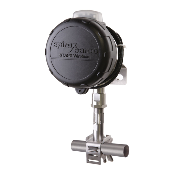
2. General product information 2.1 General description The STAPS wireless steam trap monitoring system has been designed to efficiently monitor and evaluate steam trap operation. It surveys the operation of the steam trap at regular intervals and identifies poor performance that can cause reduced plant efficiency and increased energy consumption. It can diagnose both failed-open steam traps that leak live steam, and those that have failed-closed or are blocked, resulting in waterlogging, leading to plant damage, product spoilage and health and safety concerns. - Page 9 3. Installation of the head unit assembly Note: Before actioning any installation observe the 'Safety information' in Section 1. The STAPS sensor includes the following parts: 1 off head and sensor assembly, including the head unit and sensor. Slot used for size of pipe: ½"...
- Page 10 Installation - Is there sufficient room at the sensor at the top for the head to be mounted on the pipe? Lagging - Ensure that any pipe lagging in the area where the STAPS head is to be fitted is removed before fitting.
- Page 11 3.1 Fitting the battery to the sensor head The head unit assembly requires a Tadiran SL-2880 3.6 V battery to function. Note: The head unit needs to be powered to be commissioned. However if the complete 'system' (receiver and DCS) is not in service, the battery should be removed until required. Failure to do so will considerably reduce battery life.
- Page 12 3.1.2 Turn head cover anticlockwise to unscrew. Fig. 8 Lift housing lid. Fig. 9 IM-P014-23 EMM Issue 4...
- Page 13 3.1.3 Unscrew EMC shield screws. Fig. 10 Lift EMC shield. Fig. 11 IM-P014-23 EMM Issue 4...
- Page 14 3.1.4 Ensure all packaging is removed and fit battery into holder in the head unit. Ensure that the battery is in the correct orientation as per the orientation marker (+ to top). Note: Only use a Tadiran SL-2880 Lithium Thionyl Chloride 3.6 V battery.
- Page 15 The LED response – number of flashes, follows the following pattern for each status that it is reporting; 1 flash is bad, 3 flashes are good. Time Function Action pressed < 0.2 s None The LED flashes green rapidly whilst the button is pressed. When the button is released the LED flashes red in sequence to indicate trap condition, battery status and RSSI.
- Page 16 3.2 Attaching the antenna Align the antenna pin with the antenna adaptor jack. Align antenna vertically and ensure the antenna nut is fully tightened. Fig. 14 Screw in knurled antenna nut. Fig. 15 Fig. 16 IM-P014-23 EMM Issue 4...
- Page 17 3.2.1 Fitting a remote mounted antenna Where the head unit is installed in an area with poor radio reception, an extension cable of up to 3 m length may be used to re-site the antenna and improve reception. Take the extension cable and attach one end to the antenna adaptor on the head enclosure as shown in Figure 17.
- Page 18 Refer to Section 3.3.1 for the correct installation of the heat shields, taking particular notice of the orientation shown in Figure 31. Do not use in this region Heat shield kit must be fitted Standard STAPS head Ambient temperature °C IM-P014-23 EMM Issue 4...
- Page 19 Upper (larger) heat shield The heat shield kit consists of two individual heat shields, upper and lower. Both heat shields must be fitted to achieve the optimum heat dissipation. Lower (smaller) heat shield Fig. 20 IM-P014-23 EMM Issue 4...
- Page 20 3.3.1 How to install the heat shields Remove the fixing clamp retaining nut, ensure the sensor stem does not rotate by using a 16 mm spanner on the flats provided as per Figure 21 and remove the nut as per Figure 22. Failure to do so may affect the factory set loading of the sensor.
- Page 21 Slide the upper heat shield (larger one) over the sensor stem Fig. 23 Slide larger circlip over sensor stem. Fig. 24 IM-P014-23 EMM Issue 4...
- Page 22 Using circlip pliers spread circlip and insert into groove, thus retaining heat shield. Fig. 25 Repeat procedure for the lower (smaller) heat shield. Fig. 26 IM-P014-23 EMM Issue 4...
- Page 23 Fig. 27 Fig. 28 IM-P014-23 EMM Issue 4...
- Page 24 Replace fixing clamp and retaining nut. Fig. 29 Tighten fixing clamp nut to 16 - 18 N m carefully, ensure the sensor stem does not rotate by using a 16 mm spanner on the flats provided as per Figure 30. Failure to do so may affect the factory set loading of the sensor.
- Page 25 3.4 Mounting the head unit Ensure that any pipe lagging is removed from the area where the STAPS head is to be fitted. DO NOT re- lag the STAPS Head. 3.4.1 For pipe sizes ½" to 1¼" Slide the tongue of the lower clamp into the appropriate slot of the top clamp.
- Page 26 Sensor probe Sensor probe There will be reduced functionality if the Ensure that the sensor probe is fully sensor probe is not fully compressed to compressed to the pipe the pipe Fig. 33 Fig. 32 Caution: If fitted to a hot pipe, recheck that the clamp is tight after 15 minutes. Maximum 150 mm Fig.
- Page 27 3.4.2 For pipe sizes 1½", 2" - 2½" and 3" - 4". The larger sizes use jubilee clips rather than a clamp to attach the head unit to the pipe.Separate the jubilee clips and slide over the pipe and slide them over the pipe, loosely tighten the clips to the pipe, allowing room to push the top clamp under.
- Page 28 STS 17.2 clamp assembly consists of: 'U' bolt, 2 x washers, 2 x nuts and top clamp Assemble as shown in Figure 38, positioning the sensor on the STS flange such that the STAPS assembly is as close to vertical as possible. See Figures 39 and 40.
- Page 29 5. Open or closed return line. 3.6 Device provisioning via the infrared port The STAPS head can be provisioned via its infrared port, accessed through the front glass as per Figure 42. For full details see separate software IMI. Fig. 42...
-
Page 30: Spare Parts
4. Spare parts Only the parts listed below are available for the STAPS ISA100 wireless steam trap monitoring system. No other parts are supplied as spares. Available spares Battery (Tadiran SL-2880 3.6 V battery) Enclosure 'O' ring spares kit, (includes Molykote 111 Compound sachet to seal enclosure threads) Clamp, 'T' bolt and wing nut for pipe sizes ½"... - Page 31 Alternative antenna with +4 dBi gain is available with 3 m of coaxial cable. Contact Spira x Sarc o for suitable model reference. Fig. 43 IM-P014-23 EMM Issue 4...
- Page 32 Electrostatic Hazard – Wipe only with a damp cloth. Only Tadiran SL-2880 3.6 V Lithium Thionyl Chloride batteries are permitted to be used within the STAPS wireless steam trap monitor. The enclosure is manufactured from aluminium. In rare cases, ignition sources due to impact and friction sparks could occur.
- Page 33 Product marking Fig. 44 EMC Shield Fig. 45 Enclosure casing rear facing unit nameplate IM-P014-23 EMM Issue 4...
- Page 34 Product marking - continued See Figure 48 Fig. 46 WARNING - USE ONLY Tadiran SL-2880 BATTERIES Fig. 47 AVERTISSEMENT - N’UTILISE QUE Tadiran SL-2880 BATTERIES Fig. 48 IM-P014-23 EMM Issue 4...
-
Page 35: Technical Data
6. Technical data Head unit: See Section 3 for mounting options. Integral battery Lithium Thionyl Chloride Maximum altitude 3 000 m (0.7 bar atmospheric) Ambient temperature range -20 to +70 °C Maximum pipe temperature 427 °C Maximum relative humidity 95% Enclosure rating IP66 Visual indicators IM-P014-23 EMM Issue 4... - Page 36 IM-P014-23 EMM Issue 4...
Need help?
Do you have a question about the STAPS and is the answer not in the manual?
Questions and answers