Advertisement
Quick Links
0871750/6
Installation and Maintenance Instructions
Printed in the UK
IM-P087-33 MI Issue 6
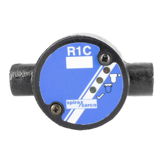
Steam Trap Failure Monitor
R1C
1. General
safety information
2. General
product information
3. Installation
4. R1C commissioning
5. BEMS/EMS
commissioning
6. Normal operation
IM-P087-33
MI Issue 6
© Copyright 2004
1
Advertisement

Related Manuals for Spirax Sarco R1C


Summary of Contents for Spirax Sarco R1C
- Page 1 MI Issue 6 Steam Trap Failure Monitor Installation and Maintenance Instructions 1. General safety information 2. General product information 3. Installation 4. R1C commissioning 5. BEMS/EMS commissioning 6. Normal operation Printed in the UK IM-P087-33 MI Issue 6 © Copyright 2004...
- Page 2 1. General safety information Your attention is drawn to Safety Information Leaflet IM-GCM-10. WARNING This product complies with the requirements of the Electromagnetic Compatibility Directive 89 / 336 / EEC by meeting the standards of:- EN 61326: 1997 A1 + A2 Emmissions - Class B Equipment Table 4. EN 61326: 1997 A1 + A2 Immunity for Industrial Locations Annex A.
- Page 3 BEMS/EMS to indicate steam trap status remotely. To detect a steam trap that is leaking steam, the R1C is used in conjunction with a Spiratec sensor chamber or steam trap fitted with a standard SS1 Spiratec sensor.
- Page 4 WLS1 waterlogging sensor assembly must be fitted. Note that the R1C will only work with Spiratec WLS1 sensors which do not have built in diode packs. WLS1 waterlogging sensor assembly with integral diode packs should not be used.
- Page 5 R1C to expose its connectors. Figure 5 shows the internal layout of the R1C. 3.2.1 Sensor wiring to R1C The R1C can be used with either a standard SS1 sensor or a WLS1 waterlogging sensor assembly. These are shown below: Standard sensor Fig.
- Page 6 3.2.2 BEMS / EMS to R1C Wiring We recommend that the R1C is connected to the BEMS /EMS via a 6 core 7 /0.2 mm cable. The cable must be installed in steel conduit. Note: To ensure no loss in performance of the R1C, other power cables should not share the same conduit.
- Page 7 Off. NPN open collector outputs. Use this output option to connect the R1C to a B /EMS whose digital inputs are pulled-up to a positive voltage: The npn outputs act like switches connected to 0 volts. During normal trap operation, the npn outputs will switch On, giving out 0 volts with an output resistance of 220 ohms.
- Page 8 See Table 9. The R1C’s modes of operation are configured with the DIL switches on the PCB. Please note: the SW1 DIL switch 1 is the test switch which should be OFF for all normal trap monitoring modes except the test modes described in Table 9.
- Page 9 BEMS /EMS set-up mode - the R1C will cyclically change it’s outputs, one step every 8 seconds. 5. BEMS /EMS commissioning An analogue output is available from the R1C as standard for use with BEMS /EMS’s that operate on an analogue input signal. Recommended BEMS /EMS setting details are given below:...
- Page 10 If the green light is not flashing, there may be a problem with the R1C. The R1C will show a failure for as long as the fault is present. If the R1C detects a transient fault, it will show the failure for at least one minute.
- Page 11 IM-P087-33 MI Issue 6...
- Page 12 IM-P087-33 MI Issue 6...
Need help?
Do you have a question about the R1C and is the answer not in the manual?
Questions and answers