
Subscribe to Our Youtube Channel
Related Manuals for Spirax Sarco UTM20 Series


Summary of Contents for Spirax Sarco UTM20 Series
- Page 1 IM-P505-02-US Issue 1 UTM20 Series Ultrasonic Transit-time Flowmeters Installation and Maintenance Instructions UTM20 Series Ultrasonic Transit-time Flowmeters © Copyright 2020 IM-P505-02-US Issue 1 Printed in US...
-
Page 2: Table Of Contents
Overview Installation Considerations Equipment Required Installing the Transducers Installing a Meter with a Remote Transmitter and Fixed Transducers Installing a Meter with a Remote Transmitter and Adjustable Transducers Installing a Panel-Mount Meter UTM20 Series Ultrasonic Transit-time Flowmeters IM-P505-02-US Issue 1... - Page 3 AquaCUE/BEACON Endpoint Wiring 8.15 RTD Interface Wiring (Energy Models Only) 8.16 Auxiliary Output Card Wiring 8.17 Installing the MicroSD Card 8.18 Connecting the USB Cable 8.19 Initial Meter Setup 9. Menu Map UTM20 Series Ultrasonic Transit-time Flowmeters IM-P505-02-US Issue 1...
- Page 4 10.16 Setup > Data Logging (Service Level Access) 10.17 Setup > Options 10.18 Setup > Passcode Setup > Security 10.19 Setup > Passcode Setup > Passcode Recovery 10.20 Display Menu 10.21 Information Menu 10.22 Diagnostics Menu 10.23 Reset Menu UTM20 Series Ultrasonic Transit-time Flowmeters IM-P505-02-US Issue 1...
- Page 5 UTM20 Flow Meters for Pipes Larger than 2" for ATEX/EICEx Hazardous Locations 14.6 UTM20 Energy Meters for Pipes 2" and Smaller 14.7 UTM20 Energy Meters for Pipes 25" and Larger 15. North American Pipe Schedules UTM20 Series Ultrasonic Transit-time Flowmeters IM-P505-02-US Issue 1...
-
Page 6: Scope Of This Manual
If damage is found, request an inspection by the carrier’s agent within 48 hours of delivery and file a claim with the carrier. A claim for equipment damage in transit is the sole responsibility of the purchaser. UTM20 Series Ultrasonic Transit-time Flowmeters IM-P505-02-US Issue 1... -
Page 7: Safety
UTM20 meter will not cause harm to the system. Important Not following instructions properly may impair safety of equipment and/or personnel. WARNING After de-energizing, delay 5 minutes before opening. UTM20 Series Ultrasonic Transit-time Flowmeters IM-P505-02-US Issue 1... -
Page 8: Introduction
By applying a scaling factor, this heat flow measurement can be expressed in various units (Btu, Watts, Joules, Kilowatts and others). UTM20 Series Ultrasonic Transit-time Flowmeters IM-P505-02-US Issue 1... -
Page 9: Dimensions
(165.10 mm) Fig. 2 2.00 in. 2.50 in. 2.00 in. (50.80 mm) (63.50 mm) (50.80 mm) Wall Mount Bracket 2.00 in. (50.80 mm) 2.50 in. (63.50 mm) 2.00 in. (50.80 mm) Fig. 3 UTM20 Series Ultrasonic Transit-time Flowmeters IM-P505-02-US Issue 1... -
Page 10: Panel Mount Enclosure
5.3 Panel Mount Enclosure 6.50" 1.38" 1.25" (165.10 mm) (35.05 mm) (31.75 mm) Ultrasonic Flow Meter 6.50" (165.10 mm) Customer supplied panel Fig. 4 UTM20 Series Ultrasonic Transit-time Flowmeters IM-P505-02-US Issue 1... -
Page 11: Operation
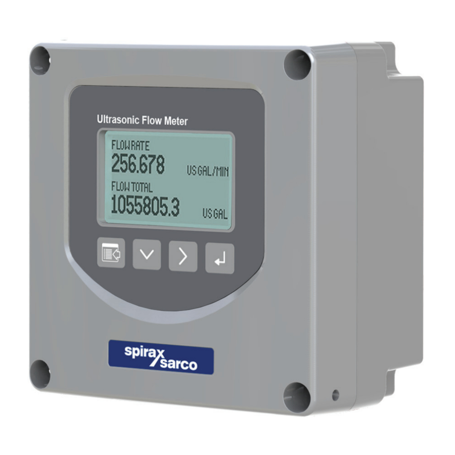
The MENU/BACK key enters menu structure. The DOWN ARROW key toggles between flow rate, flow total, velocity and flow rate with flow total. The RIGHT ARROW key has no function. The ENTER key has no function. UTM20 Series Ultrasonic Transit-time Flowmeters IM-P505-02-US Issue 1... -
Page 12: Keypad Operation In The Menu Structure
MENU/BACK returns to parent menu (up a level). If at the Main (top level) menu, returns to the Home Screen. DOWN ARROW scrolls the list. RIGHT ARROW and ENTER have the same function in the menu structure and advance to the submenu or to read/edit a parameter. UTM20 Series Ultrasonic Transit-time Flowmeters IM-P505-02-US Issue 1... -
Page 13: Selecting An Option In A Parameter Selection List
ENTER selects the option and the box on the left side fills in to show the item is selected. MENU/BACK exits parameter editing and returns to the parent menu (up a level). UTM20 Series Ultrasonic Transit-time Flowmeters IM-P505-02-US Issue 1... -
Page 14: Entering A Number
DOWN ARROW cycles through the numbers and other options. RIGHT ARROW moves the cursor to the right. Once it reaches the rightmost digit or a space, the cursor moves to the leftmost digit. ENTER accepts the value. UTM20 Series Ultrasonic Transit-time Flowmeters IM-P505-02-US Issue 1... -
Page 15: Installation
Four #8 or M4 screws, if mounting the transmitter on a wall Stainless steel banding straps, if mounting the transmitter on a pipe 7.4 Installing the Transducers See the user manual for your particular transducer for installation instructions. UTM20 Series Ultrasonic Transit-time Flowmeters IM-P505-02-US Issue 1... -
Page 16: Installing A Meter With A Remote Transmitter And Fixed Transducers
If necessary, you can rotate the mounting bracket in 90° increments to accommodate the final orientation of the transmitter. From inside the enclosure, remove the 4 screws holding the bracket. Rotate the bracket and replace the screws. See Figure 10. UTM20 Series Ultrasonic Transit-time Flowmeters IM-P505-02-US Issue 1... - Page 17 Partially loosen the 2 enclosure captive screws on the left side of the transmitter cover. Completely loosen the 2 screws on the right side. Grasp and lift the cover and open it to the left. The cover remains attached and the left screws act as a hinge. UTM20 Series Ultrasonic Transit-time Flowmeters IM-P505-02-US Issue 1...
- Page 18 Use conduit holes where cables enter the enclosure from the bottom. Use suitably certified plugs to seal any holes that are not used for cable entry. A cable gland kit is included for inserting the transducer and power cables. UTM20 Series Ultrasonic Transit-time Flowmeters IM-P505-02-US Issue 1...
- Page 19 10. Plug the wired terminal blocks into the main board. 11. Reassemble the cover. Torque the cover screws to 45 in-lb. 12. Set up the meter. See “Initial Meter Setup” on page 41 for instructions. UTM20 Series Ultrasonic Transit-time Flowmeters IM-P505-02-US Issue 1...
-
Page 20: Installing A Meter With A Remote Transmitter And Adjustable Transducers
If necessary, you can rotate the mounting bracket in 90° increments to accommodate the final orientation of the transmitter. From inside the enclosure, remove the 4 screws holding the bracket. Rotate the bracket and replace the screws. See Figure 17. UTM20 Series Ultrasonic Transit-time Flowmeters IM-P505-02-US Issue 1... - Page 21 Partially loosen the 2 enclosure captive screws on the left side of the transmitter cover. Completely loosen the 2 screws on the right side. Grasp and lift the cover and open it to the left. The cover remains attached and the left screws act as a hinge. UTM20 Series Ultrasonic Transit-time Flowmeters IM-P505-02-US Issue 1...
- Page 22 Use conduit holes where cables enter the enclosure from the bottom. Use suitably certified plugs to seal any holes that are not used for cable entry. A cable gland kit is included for inserting the transducer and power cables. UTM20 Series Ultrasonic Transit-time Flowmeters IM-P505-02-US Issue 1...
- Page 23 Install the adjustable transducers according to instructions in the transducer user manual. 10. Wire the transducers to the transmitter. 11. Plug the wired terminal blocks into the main board. 12. Reassemble the cover. Torque the cover screws to 45 in-lb. UTM20 Series Ultrasonic Transit-time Flowmeters IM-P505-02-US Issue 1...
-
Page 24: Installing A Panel-Mount Meter
(144.78 mm) 5.70 in. Ø 0.252". thru typ. (144.78 mm) 2.85 in. 5.50 in. (72.39 mm) (139.70 mm) 4.80 in. (121.92 mm) 2.85 in. (72.39 mm) Fig. 25 Panel cut out dimensions UTM20 Series Ultrasonic Transit-time Flowmeters IM-P505-02-US Issue 1... - Page 25 Frame Customer-supplied panel 'O' rings (×4) Screws (×4) Fig. 26 Installation exploded view UTM20 Series Ultrasonic Transit-time Flowmeters IM-P505-02-US Issue 1...
- Page 26 TB700 Digital I/O Connector TB400 Power Connector TB900 TB600 Analog Connector Output Connector LEDs Accessory Card TB300 Transducer TB600 Analog Output Micro USB Mini B Connector SD Card Connector Holder Fig. 28 Wiring connectors UTM20 Series Ultrasonic Transit-time Flowmeters IM-P505-02-US Issue 1...
- Page 27 Wire 20 AWG UL AWM 1007 Type 1007 Transducer Cables Badger Meter supplied cable Digital Outputs/Inputs, Current Output, RS485, RTD or Encoder Interface Wire 28 to 12 AWG UL AWM 1007 Type 1007 UTM20 Series Ultrasonic Transit-time Flowmeters IM-P505-02-US Issue 1...
- Page 28 (+) and the white wire is negative (-). For the red and black combination, the red wire is positive (+) and the black wire is negative (-). The transducer wires are labeled to indicate which pair is upstream or downstream. UTM20 Series Ultrasonic Transit-time Flowmeters IM-P505-02-US Issue 1...
- Page 29 Observe upstream and downstream orientation and wire polarity. See below. Inner Shield Transducer Outer Shield Upstream+ TB300 Upstream- Black Green (2) 69039, Triax Cable Downstream+ Black Downstream- Fig. 31 Upstream/downstream transducer UTM20 Series Ultrasonic Transit-time Flowmeters IM-P505-02-US Issue 1...
- Page 30 External Equipment or Circuit Breaker Power Supply (9 . . . 28V DC) Power Supply (Return) (Acceptable wire sizes: 28 to 12 AWG) Chassis Ground Fig. 32 Power supply 9 to 28V DC UTM20 Series Ultrasonic Transit-time Flowmeters IM-P505-02-US Issue 1...
- Page 31 External Equipment or Circuit Breaker Power Supply (20 . . . 26V AC)Power Supply (Return) (Acceptable wire sizes: 28 to 12 AWG) Chassis Ground Fig. 33 Power supply 20 to 28V AC UTM20 Series Ultrasonic Transit-time Flowmeters IM-P505-02-US Issue 1...
- Page 32 (Main power wiring must be of material VW-1 or better.) Factory (Acceptable wire sizes: Wired Chassis Ground Protective 18 to 12 AWG) Ground Connect protective earth conductor to terminal 3. Fig. 34 AC/DC power connections UTM20 Series Ultrasonic Transit-time Flowmeters IM-P505-02-US Issue 1...
- Page 33 ISO_GND Common Note: 4 to 20 OUT 2 available with Energy model only. 800 Ohms max. Fig. 36 Power Typical 4-20 mA interface using external Typ 24V DC isolated 24V DC source UTM20 Series Ultrasonic Transit-time Flowmeters IM-P505-02-US Issue 1...
- Page 34 Control Output #2 If required Control Output #3 Control Output #3 ISO_GND ISO_GND (Acceptable wire sizes: 28 to 12 AWG) Fig. 37 Typical control out 1, 2 and 3 interface with internal pullups active UTM20 Series Ultrasonic Transit-time Flowmeters IM-P505-02-US Issue 1...
- Page 35 If required Sink Control Output #3 Control Output #3 ISO_GND ISO_GND ISO_GND (Acceptable wire sizes: 28 to 12 AWG) Fig. 38 Typical control out 1, 2 and 3 interface with external pullups passive UTM20 Series Ultrasonic Transit-time Flowmeters IM-P505-02-US Issue 1...
- Page 36 External Equipment RS485 + RS485 − Fig. 39 Typical RS485 interface 8.13 Digital Input Wiring TB700 Push-button Reset Total + Reset Total - 5 to 30V DC Fig. 40 Digital input—reset totalizer UTM20 Series Ultrasonic Transit-time Flowmeters IM-P505-02-US Issue 1...
- Page 37 RTD1 Ex - PT100 or PT1000 RTDs RTD2 Ex + RTD2 Sense + RTD2 Sense - RTD2 Ex - Temp #2 (Acceptable wire sizes: 28 to 12 AWG) Chassis_GND Fig. 42 Two-wire RTD interface UTM20 Series Ultrasonic Transit-time Flowmeters IM-P505-02-US Issue 1...
- Page 38 RTD1 Ex - PT100 or PT1000 RTDs RTD2 Ex + RTD2 Sense + RTD2 Sense - RTD2 Ex - Temp #2 (Acceptable wire sizes: 28 to 12 AWG) Chassis_GND Fig. 44 Four-wire RTD interface UTM20 Series Ultrasonic Transit-time Flowmeters IM-P505-02-US Issue 1...
- Page 39 8.16 Auxiliary Output Card Wiring +V DC (30V DC, 5A max., each output) AUX2 OUT TB100 Power supply AUX1 OUT Load 1 Load 2 Fig. 45 Auxiliary output interface UTM20 Series Ultrasonic Transit-time Flowmeters IM-P505-02-US Issue 1...
- Page 40 Connect the USB cable to the mini USB port, aligning the pins in the cable with the holes in the port. Program the transmitter. Remove the USB cable and close the enclosure cover. UTM20 Series Ultrasonic Transit-time Flowmeters IM-P505-02-US Issue 1...
- Page 41 6. Set up the flow settings: In the SETUP > METER > FLOW SETUP menu, select flow direction, low and maximum flow cutoff, and minimum and maximum signal strength. UTM20 Series Ultrasonic Transit-time Flowmeters IM-P505-02-US Issue 1...
- Page 42 Flow Rate / Flow Total *Energy Rate / Energy Total *Energy Rate Time / Date RecoveryPasscodeSetup Energy units only. Optional card installed. Based on selected option. Available when security is enabled. Press to toggle the options. UTM20 Series Ultrasonic Transit-time Flowmeters IM-P505-02-US Issue 1...
- Page 43 Threshold Min. Logout Timeout BACnet/IP Threshold Passcode Recovery Modbus TCP/IP Max. Threshold Time EtherNet/IP Delete Log Date Power On Time Simulation Mode Passcode Level Option Clear History Factory Reset Reboot Card Type UTM20 Series Ultrasonic Transit-time Flowmeters IM-P505-02-US Issue 1...
- Page 44 Requires operator level passcode or higher if security is enabled. An asterisk (*) indicates the parameter default. UTM20 Series Ultrasonic Transit-time Flowmeters IM-P505-02-US Issue 1...
- Page 45 Any flow in forward and reverse direction *GROSS FLOW FLOW TOTAL FORWARD FLOW Forward flow minus reverse flow A MODE REVERSE FLOW negative total results when reverse flow is NET FLOW greater than forward flow UTM20 Series Ultrasonic Transit-time Flowmeters IM-P505-02-US Issue 1...
- Page 46 FORWARD FLOW REVERSE FLOW ENERGY TOTAL negative total results when reverse flow is NET FLOW MODE greater than the forward flow (Energy Units Only) *GROSS FLOW Any flow in forward and reverse direction UTM20 Series Ultrasonic Transit-time Flowmeters IM-P505-02-US Issue 1...
- Page 47 Home Screen by pressing the DOWN button *FLOW RATE ENERGY TOTAL FLOW TOTAL TEMP #1 / TEMP #2 DISPLAY MODE VELOCITY ENERGY RATE / DELTA TEMPERATURE RATE/TOTAL ENERGY RATE / ENERGY TOTAL ENERGY RATE TIME / DATE UTM20 Series Ultrasonic Transit-time Flowmeters IM-P505-02-US Issue 1...
- Page 48 CK: 1½" COPPER CL: 2" COPPER CM: ½" SS TUBE CN: ¾" SS TUBE CP: 1" SS TUBE CQ: 1¼" SS TUBE CR: 1½" SS TUBE CS: 2 SS IN TUBE CT: 1" COPPER UTM20 Series Ultrasonic Transit-time Flowmeters IM-P505-02-US Issue 1...
- Page 49 GLASS PYREX MATERIAL EBONITE POLYSTYRENE FIBERGLASS EPOXY MORTAR RUBBER LINER Numeric entry; min 0 00, max 5 in (125 mm) THICKNESS Numeric display in" or millimeters, based on PIPE TYPE I.D. SIZE UTM20 Series Ultrasonic Transit-time Flowmeters IM-P505-02-US Issue 1...
- Page 50 SPACING the scale on the rails, if used See the transducer user manual For Cx transducers with fixed spacing, the parameter will not be shown UTM20 Series Ultrasonic Transit-time Flowmeters IM-P505-02-US Issue 1...
- Page 51 Select the units for the manual reference temperature REF TEMP UNITS *ENABLED Flow rate compensation based on fluid Reynolds number as REYNOLDS DISABLED the fluid changes from laminar to transitional to turbulent flow UTM20 Series Ultrasonic Transit-time Flowmeters IM-P505-02-US Issue 1...
- Page 52 Enter the value as a percentage of actual flow rate For instance, a Hysteresis setting of 5% allows the flow to vary ± 5% from the currently established flow rate without automatically decreasing the value of the Damping UTM20 Series Ultrasonic Transit-time Flowmeters IM-P505-02-US Issue 1...
- Page 53 In Figure 41 , flow data falls outside the flow Hysteresis window but does not reach the minimum time specified in the Bad Data Rejection window When data appears that is outside the Hysteresis band and shorter than the Bad Data Rejection window time, the data is rejected UTM20 Series Ultrasonic Transit-time Flowmeters IM-P505-02-US Issue 1...
- Page 54 Hysteresis window to correspond with the new established flow rate Old ±10% Hysteresis 4 Samples Outside Flow Outside Original Limit Hysteresis Limit Hysteresis Limit Bad Data Rejection Window ±10% Hysteresis Limit Flow Fig. 49 New valid flow data UTM20 Series Ultrasonic Transit-time Flowmeters IM-P505-02-US Issue 1...
- Page 55 Each transducer pair has a CAL FACTOR and SENSOR FACTOR on the label Verify FACTOR MODE is set to FIELD and enter the factors from the transducer into the CAL FACTOR and SENSOR FACTOR settings Zero the meter after entering the CAL FACTOR and SENSOR FACTOR UTM20 Series Ultrasonic Transit-time Flowmeters IM-P505-02-US Issue 1...
- Page 56 TRIM 4 mA DCS/BAS reads the desired value Available only when OUTPUT SOURCE is in TEST MODE Set the test current to 20 TRIM 20 mA mA Adjusts output until PLC/DCS/BAS reads 20 mA UTM20 Series Ultrasonic Transit-time Flowmeters IM-P505-02-US Issue 1...
- Page 57 1000 Hz Available when TEST MODE is selected for OUTPUT SOURCE To TEST check the wiring to the control system or device, you can override FREQUENCY the frequency output with a fixed frequency UTM20 Series Ultrasonic Transit-time Flowmeters IM-P505-02-US Issue 1...
- Page 58 (Flow Direction meters only: flow is forward or reverse When the absolute Mode) DIRECTION ENERGY value of the flow rate is below the cutoff, the FORWARD output will not be active. ENERGY REVERSE UTM20 Series Ultrasonic Transit-time Flowmeters IM-P505-02-US Issue 1...
- Page 59 LATCHING is DISABLED Numeric entry Default is 100 ms Numeric entry Units: Milliseconds MIN ON-TIME Default is 200 ms INTERNAL See “Digital Outputs Wiring” on page 34 PULL UP RESISTOR *EXTERNAL UTM20 Series Ultrasonic Transit-time Flowmeters IM-P505-02-US Issue 1...
- Page 60 HYSTERESIS chattering The parameter is only valid if LATCHING is DISABLED Numeric entry Default is 100 ms Numeric entry Units: Milliseconds MIN ON-TIME Default is 200 ms UTM20 Series Ultrasonic Transit-time Flowmeters IM-P505-02-US Issue 1...
- Page 61 Compare the temperature of the heat source with the temperature reading of Temp 1 on the display In SoloCUE, adjust the Trim RTD 1 until Temp 1 matches the heat source temperature Repeat steps #3 and #4 for RTD 2 Fig. 50 Trimming the RTDs UTM20 Series Ultrasonic Transit-time Flowmeters IM-P505-02-US Issue 1...
- Page 62 Flow Total Reset (cannot set up meter) READ ONLY allows read only BACNET MS/TP SETTINGS MAX MASTER Numeric entry 1 to 127 *NONE PARITY ODD PARITY EVEN PARITY *1 STOP BIT STOP BIT 2 STOP BITS DISABLED RESISTOR *ENABLED UTM20 Series Ultrasonic Transit-time Flowmeters IM-P505-02-US Issue 1...
- Page 63 100 MbIt HALF DUPLEX 100 Mbit FULL DUPLEX WRITE/READ allows full access RESET/READ allows you to read any, but only write to ACCESS Flow Total Reset (cannot set up meter) *READ ONLY allows read only UTM20 Series Ultrasonic Transit-time Flowmeters IM-P505-02-US Issue 1...
- Page 64 100 MbIt HALF DUPLEX 100 Mbit FULL DUPLEX WRITE/READ allows full access RESET/READ allows you to read any, but only write to ACCESS Flow Total Reset (cannot set up meter) *READ ONLY allows read only UTM20 Series Ultrasonic Transit-time Flowmeters IM-P505-02-US Issue 1...
- Page 65 100 MbIt HALF DUPLEX 100 Mbit FULL DUPLEX WRITE/READ allows full access RESET/READ allows you to read any, but ACCESS only write to Flow Total Reset (cannot set up meter) *READ ONLY allows read only UTM20 Series Ultrasonic Transit-time Flowmeters IM-P505-02-US Issue 1...
- Page 66 If THRESHOLD log model is selected, Numeric entry (plus or minus) MAX THRESHOLD this setting will be active DELETE LOG Will stop recording and delete all records Prompt with a confirmation screen UTM20 Series Ultrasonic Transit-time Flowmeters IM-P505-02-US Issue 1...
- Page 67 Numeric entry 6-digit passcode Numeric entry SET SERVICE 1 MINUTE 5 MINUTES *10 MINUTES When logout occurs, the display returns to the Home Screen LOGOUT TIMEOUT 20 MINUTES 30 MINUTES 60 MINUTES UTM20 Series Ultrasonic Transit-time Flowmeters IM-P505-02-US Issue 1...
- Page 68 15 minutes, the recovery mode is canceled and you must request a new recovery code to reset the passcodes TEMPORARY PASSCODE can be entered from the SoloCUE software utility or the front panel, regardless of what was used to start it UTM20 Series Ultrasonic Transit-time Flowmeters IM-P505-02-US Issue 1...
- Page 69 DISPLAY TIME 24 HOUR AM / PM and on the SoloCUE dashboard YYYY-MM-DD Select format of the date to display on the Home Screen MM-DD-YYYY DISPLAY DATE and on the SoloCUE dashboard DD-MM-YYYY UTM20 Series Ultrasonic Transit-time Flowmeters IM-P505-02-US Issue 1...
- Page 70 COUNT exceeds the digits in the display The ENERGY OVERFLOW is a counter that increments each time ENERGY OVERFLOW Numeric integer the energy total exceeds the digits in the display UTM20 Series Ultrasonic Transit-time Flowmeters IM-P505-02-US Issue 1...
- Page 71 Read only Ethernet card must be installed MAC ADDRESS OPTIONS and cable must be connected for the MAC Address to display Read only Ethernet link status CONNECTED LINK STATUS if Ethernet card is installed and DISCONNECTED enabled UTM20 Series Ultrasonic Transit-time Flowmeters IM-P505-02-US Issue 1...
- Page 72 Any settings made will be reset Reboots the device The UTM20 meter does not require this manual REBOOT confirmation REBOOT REBOOT for any procedure, screen but it may be useful for system troubleshooting UTM20 Series Ultrasonic Transit-time Flowmeters IM-P505-02-US Issue 1...
- Page 73 ENTER ) Select OK to confirm reset After selecting RESET FLOW TOTAL, you are prompted to confirm the reset of the flow total Press ENTER to confirm or press MENU/BACK to cancel UTM20 Series Ultrasonic Transit-time Flowmeters IM-P505-02-US Issue 1...
- Page 74 Home Screen 11.4 View Alarm and Message Buffer Up to 30 alarm or warning message codes are buffered on a first-in-first-out basis To view the buffer, go to DIAGNOSTICS > HISTORY. UTM20 Series Ultrasonic Transit-time Flowmeters IM-P505-02-US Issue 1...
- Page 75 Mode Change Aux Output #2 from Test C52 AUX #2 SWITCH TEST Aux Output #2 is forced on or off Mode C60 SIMULATION MODE Meter is running flow simulation Deactivate Simulation Mode UTM20 Series Ultrasonic Transit-time Flowmeters IM-P505-02-US Issue 1...
- Page 76 Check flow rate and Set High setting S41 HIGH FLOW setting for Output #2 Flow rate is above high flow alarm Check flow rate and Set High setting S42 HIGH FLOW setting for Output #3 UTM20 Series Ultrasonic Transit-time Flowmeters IM-P505-02-US Issue 1...
- Page 77 #1 Check alarm settings for Aux S73 TEMP #2 LOW Output #1 Check fluid temperature and RTD Temp #1 is below low alarm setting #1 Check alarm settings for Aux S74 TEMP #2 LOW Output #2 UTM20 Series Ultrasonic Transit-time Flowmeters IM-P505-02-US Issue 1...
- Page 78 Temp #2 is below low alarm setting Check alarm settings for Output #3 Check fluid temperature and RTD Temp #2 is below low alarm setting #2 Check alarm settings for Aux S93 TEMP #2 LOW Output #1 UTM20 Series Ultrasonic Transit-time Flowmeters IM-P505-02-US Issue 1...
- Page 79 Calibration changed from Field to Factory I13 FIELD CALIBRATION Calibration changed from Factory to Field Firmware updated I21 FIRMWARE CHANGED Flow total reset to zero I31 FLOW TOTAL RESET MicroSD card not installed I41 NO SD CARD UTM20 Series Ultrasonic Transit-time Flowmeters IM-P505-02-US Issue 1...
- Page 80 Pipes may develop scale, product build-up or corrosion over time As a result, the effective wall thickness may be different than a new pipe and wall thickness or liner parameters may need to be adjusted At the transmitter: Verify that pipe parameters match the installation UTM20 Series Ultrasonic Transit-time Flowmeters IM-P505-02-US Issue 1...
- Page 81 Symptoms: Current, frequency or pulse outputs do not match the readings. Incorrect parameter settings Possible Causes Wiring or control system configuration issues Recommended Verify that the parameters for the output are set properly Action UTM20 Series Ultrasonic Transit-time Flowmeters IM-P505-02-US Issue 1...
- Page 82 Unplug the wire connector from the terminal block on the AC module. Remove the remaining (4) M3 pan head phillips screws and lock washers that secure the AC module to the enclosure base. Remove the AC module. Installation is in the reverse order. UTM20 Series Ultrasonic Transit-time Flowmeters IM-P505-02-US Issue 1...
- Page 83 Do not misalign the pins. Do not use excessive force. Fig. 52 Replacing the Communication or Dry Contact Board UTM20 Series Ultrasonic Transit-time Flowmeters IM-P505-02-US Issue 1...
- Page 84 Back up the device configuration prior to updating the firmware. See "UTM20 Firmware Update" (available at www. badgermeter.com) for more information. UTM20 Series Ultrasonic Transit-time Flowmeters IM-P505-02-US Issue 1...
- Page 85 JZ, KZ, LZ, NZ and RZ Transducers: Ex ec IIC T6 Gc; Ex tc IIIB T60 °C Dc; Tamb: -25 to 60 °C Not available with UZ, CA to CT, or HZ transducers; flexible conduit, Auxiliary Dry Contact card or AquaCUE/BEACON endpoints UTM20 Series Ultrasonic Transit-time Flowmeters IM-P505-02-US Issue 1...
- Page 86 Mega calories, Kilowatt-hour, Megawatt hour, Kilojoules, Mega joules, (energy meters) Ton-hour (Refrigeration) Btu/hour, Thousand Btu/hour, Millions Btu/hour, Ton (Refrigeration), Heat/cooling rate Watts, Kilowatts, Megawatts, Kilojoules/hour, Mega joules/hour, (energy meters) Kilocalories/hour, Mega calories/hour Temperature Farenheit, Celcius, Kelvin (energy meters) UTM20 Series Ultrasonic Transit-time Flowmeters IM-P505-02-US Issue 1...
- Page 87 8 GB card, included with transmitter slot Records 150 previous alarms, warnings or errors Alarms Languages English, French, German, Italian, Spanish Four levels: Read-only, Operator, Service and Admin; 6-digit passcode number; selectable Security auto logout UTM20 Series Ultrasonic Transit-time Flowmeters IM-P505-02-US Issue 1...
- Page 88 Large pipe transducers are recommended for 8 to 12" pipes if normal velocity is expected to be greater than 12 ft/s (3 6 m/s) Consult factory for larger pipe sizes Not for metric pipes UTM20 Series Ultrasonic Transit-time Flowmeters IM-P505-02-US Issue 1...
- Page 89 Used to configure, calibrate and troubleshoot flow meters and control valves; Software is SoloCUE compatible with Windows 7, 8, 10 USB Cable RC820648 USB 2 0 mini B connector to A connector, shielded UTM20 Series Ultrasonic Transit-time Flowmeters IM-P505-02-US Issue 1...
- Page 90 15 feet (4.5 m) Conduit Type and Length (Conduit length 30 feet (9 m) is less than or equal to cable length) 50 feet (15 m) 75 feet (23 m) 100 feet (30 m) UTM20 Series Ultrasonic Transit-time Flowmeters IM-P505-02-US Issue 1...
- Page 91 Units of Measure Gallons/gallons per minute (field selectable, additional options available) Totalizer/Flow Rate Factory Calibrated Testing & Tagging Factory Calibrated/Stainless Steel Tag Stainless steel tube ½" to 2". options are available. Part number sequence UTM20 Series Ultrasonic Transit-time Flowmeters IM-P505-02-US Issue 1...
- Page 92 ½" NPT Threads, Nickel Plated Brass cable glands ½" NPT Threads, no cable glands Hardware M20 Threads, Poly cable glands M20 Threads, Nickel Plated Brass cable glands M20 Threads, no cable glands None Endpoint Wiring Method UTM20 Series Ultrasonic Transit-time Flowmeters IM-P505-02-US Issue 1...
- Page 93 Factory Calibrated Testing & Tagging Factory Calibrated/Stainless Steel Tag Stainless steel tube ½" to 2". options are available. For hazardous location units, Remote Cable and Conduit Length codes must match Part number sequence UTM20 Series Ultrasonic Transit-time Flowmeters IM-P505-02-US Issue 1...
- Page 94 450 feet (137) (DTTL "LZ" and "YZ" only) 500 feet (152 m) (DTTL "LZ" and "YZ" only) 550 feet (168) (DTTL "LZ" and "YZ" only) 600 feet (183 m) (DTTL "LZ" and "YZ" only) UTM20 Series Ultrasonic Transit-time Flowmeters IM-P505-02-US Issue 1...
- Page 95 Factory Calibrated Testing & Tagging Factory Calibrated/Stainless Steel Tag Stainless steel tube ½" to 2". options are available. For hazardous location units, Remote Cable and Conduit Length codes must match Part number sequence UTM20 Series Ultrasonic Transit-time Flowmeters IM-P505-02-US Issue 1...
- Page 96 ½" NPT Threads, Nickel Plated Brass cable glands ½" NPT Threads, no cable glands Hardware M20 Threads, Poly cable glands M20 Threads, Nickel Plated Brass cable glands M20 Threads, no cable glands None Endpoint Wiring Method UTM20 Series Ultrasonic Transit-time Flowmeters IM-P505-02-US Issue 1...
- Page 97 Factory Calibrated Testing & Tagging Factory Calibrated/Stainless Steel Tag Stainless steel tube ½" to 2". options are available. For hazardous location units, Remote Cable and Conduit Length codes must match Part number sequence UTM20 Series Ultrasonic Transit-time Flowmeters IM-P505-02-US Issue 1...
- Page 98 M20 Threads, Nickel Plated Brass cable glands M20 Threads, no cable glands Endpoint Wiring Method None Standard Output (Modbus RTU or BACnet MS/TP field selectable) Standard Output plus Modbus TCP Ethernet Communication/Output Standard Output plus BACnet/IP Ethernet UTM20 Series Ultrasonic Transit-time Flowmeters IM-P505-02-US Issue 1...
- Page 99 Gallons/gallons per minute (field selectable, additional options Units of Measure Totalizer/Flow Rate available) Factory Calibrated Testing & Tagging Factory Calibrated/Stainless Steel Tag Submersible transducer cables use two conduit openings.Note: Check for availability. Part number sequence UTM20 Series Ultrasonic Transit-time Flowmeters IM-P505-02-US Issue 1...
- Page 100 (Conduit length is less 30 feet (9 m) than or equal to cable length) 50 feet (15 m) 75 feet (23 m) 100 feet (30 m) Surface, Commercial RTD Type None (user provided) UTM20 Series Ultrasonic Transit-time Flowmeters IM-P505-02-US Issue 1...
- Page 101 Units of Measure Energy Kilowatt-hour/Watt (field selectable, additional options available) Totalizer/Rate Factory Calibrated Testing & Tagging Factory Calibrated/Stainless Steel Tag Stainless steel tube ½" to 2". options are available. Part number sequence UTM20 Series Ultrasonic Transit-time Flowmeters IM-P505-02-US Issue 1...
- Page 102 (Conduit length is less 75 feet (23 m) than or equal to cable length) 100 feet (30 m) 150 feet (46 m) 200 feet (61 m) 250 feet (76 m) 300 feet (90 m) UTM20 Series Ultrasonic Transit-time Flowmeters IM-P505-02-US Issue 1...
- Page 103 Kilowatt-hour/Kilowatt (field selectable, additional options available) Totalizer/Rate Testing & Tagging Factory Calibrated Factory Calibrated/Stainless Steel Tag Contact factory for DTTL cable lengths longer than 300 ft. Submersible transducer cables use two conduit openings. Part number sequence UTM20 Series Ultrasonic Transit-time Flowmeters IM-P505-02-US Issue 1...
- Page 104 5.761 0.432 5.501 0.562 5.187 0.719 8.625 7.813 0.406 7.625 0.500 7.625 0.500 7.437 0.594 7.178 0.719 6.183 1.221 10.75 9.750 0.500 9.75 0.500 9.562 0.594 9.312 0.719 9.062 0.844 8.500 1.125 UTM20 Series Ultrasonic Transit-time Flowmeters IM-P505-02-US Issue 1...
- Page 105 6.357 0.134 6.065 0.280 6.065 0.280 8.625 8.407 0.109 8.329 0.148 8.125 0.250 8.071 0.277 7.981 0.322 7.981 0.322 10.75 10.482 0.134 10.42 0.165 10.25 0.250 10.13 0.310 10.02 0.365 10.02 0.365 UTM20 Series Ultrasonic Transit-time Flowmeters IM-P505-02-US Issue 1...
- Page 106 2.625 2.625 2.625 2.875 2.500 Wall 0.095 0.080 0.065 0.188 0.050 2.435 2.465 2.495 2.500 2.400 3.125 3.125 3.125 3.500 3.000 Wall 0.109 0.090 0.072 0.219 0.050 2.907 2.945 2.981 3.062 2.900 UTM20 Series Ultrasonic Transit-time Flowmeters IM-P505-02-US Issue 1...
- Page 107 0.078 7.062 6.844 8.125 8.125 8.125 8.625 8.000 Wall 0.271 0.200 0.170 0.313 0.094 7.583 7.725 7.785 8.000 7.812 10.125 10.125 10.125 10.000 Wall 0.338 0.250 0.212 0.094 9.449 9.625 9.701 9.812 UTM20 Series Ultrasonic Transit-time Flowmeters IM-P505-02-US Issue 1...
- Page 108 UTM20 Series Ultrasonic Transit-time Flowmeters IM-P505-02-US Issue 1...
Need help?
Do you have a question about the UTM20 Series and is the answer not in the manual?
Questions and answers