
Related Manuals for Spirax Sarco MTL10 Inline


Summary of Contents for Spirax Sarco MTL10 Inline
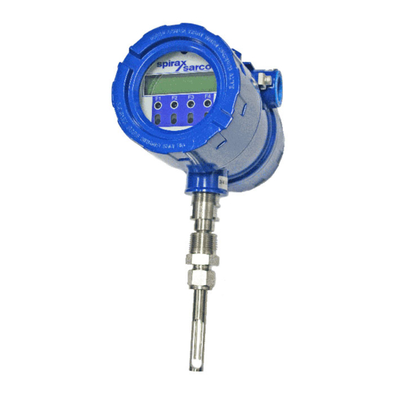
- Page 1 INSTALLATION AND MAINTENANCE INSTRUCTIONS IM-8-632-US June 2015 Thermal Mass Flowmeter and Temperature Transmitter MTI10 Insertion and MTL10 Inline...
- Page 2 Phone: 800.356.9362 Fax: 303.682.7069 www.spiraxsarco.com/us Spirax Sarco believes that the information provided herein is accurate; however, be advised that the information contained herein is NOT a guarantee for satisfactory results. Specifically, this information is neither a warranty nor guarantee, expressed or implied, regarding performance, merchantability, fitness, or any other matter with respect to the products;...
-
Page 3: Table Of Contents
Table Of Contents 1. Introduction ........................Page 4 2. Installation (Mechanical) ....................Page 8 a. Insertion Type ....................Page 9 b. Inline Type ....................Page 13 3. Wiring (Electrical) ......................Page 15 a. Input Power ....................Page 17 b. Signal Wiring ....................Page 19 c. Frequency/Alarm Wiring ................Page 21 d. -
Page 4: Introduction
Introduction Welcome Thank you for purchasing the Spirax Sarco MTI10 insertion or MTL10 inline Thermal Mass Gas Flowmeter and Temperature Transmitter. The Model MTI10/MTL10 is one of the most technically advanced flowmeters in the world. The MTI10/MTL10 utilize the same sensor and electronics. The MTL10 includes a company supplied flow tube, while the MTI10 is inserted into an existing pipe. Extensive engineering effort has been invested to deliver advanced features, accuracy measurement performance and outstanding reliability. - Page 5 Introduction Calibration Calibration Validation Spirax Sarco has developed a method to validate the calibration of the Validation flowmeter in the field. This method is called Calibration Validation and it is made up of two distinct tests: CAL-V™ and Zero CAL-CHECK™. The goal of Calibration Validation is to provide operators with the...
- Page 6 Introduction flow/maximum frequency, units-per-pulse or pulse-per-units. The maximum frequency is 100 Hz. An isolated 24VDC output power option is provided for use with these outputs. It can supply a 42mA maximum total load (do not use for other external devices). MTI10/MTL10 View interfaces to the USB port and is a free PC- based software program that displays flowmeter readings and permits flowmeter configuration. RS485 Modbus, and industry standard communication option, is available on the MTI10/MTL10 flow meter.
- Page 7 Introduction Functional Functional Diagram An optional on-board display is available to view flow rate, total flow, Diagram elapsed time, process gas temperature and alarms. The display is also used in conjunction with the Configuration Panel for field configuration of flowmeter settings such as 4 to 20mA scaling, pulse output frequency scaling, pipe area, zero flow cutoff, flow filtering or damping, display configurations, diagnostics and alarm limits. Fig. 1.2: Functional Diagram Standard I/O 24VDC Input Power 4 to 20 mA Flow 100-240VAC Optional 4 to 20 mA Flow or Temperature Optional Display and Con guration Panel Frequency or Alarm Contact Input Standard Digital Communications...
-
Page 8: Installation (Mechanical)
Installation: General Installation - Scope This section describes how to install the Spirax Sarco MTI10/MTL10 MTI10/MTL10 Flowmeter and how to get started. Installation methods will vary Flowmeter according to the flowmeter type (insertion or inline). For Insertion Types (MTI10): 1. Determine lateral position on the pipe 2. Sensor installation depth 3. - Page 9 Installation: Insertion Type Insertion Instructions for Insertion Flowmeter Lateral Placement Install the Model MTI10 Insertion style flowmeter so that it is far enough Flowmeter Lateral away from bends in the pipe, obstructions, or changes in line sizes Placement to ensure a consistent flow profile. Fifteen diameters of straight pipe upstream and ten downstream are recommended. For example, a 2" pipe would require 30" upstream and 20" downstream, but a 4" pipe would require 60" upstream and 40" downstream. Fig. 2.1: Upstream and Downstream Pipe IDs for Insertion Meters Proper Profile FLOW...
- Page 10 22mm (0.87") past the center line of the pipe. Fig. 2.2: Cross Section of Insertion Sensor Depth in Pipe Compression Fitting Half Coupling, (Supplied by Spirax Sarco) 3/4" NPT Female (Supplied by Customer) Customer’s Pipe...
- Page 11 Installation: Insertion Type Sensor Orientation Fig. 2.3: Orientation of MTI10 Insertion Type Flowmeter - Direction of Flow Flow Direction Arrow Pipe FLOW Note: Some flowmeters are shipped with the sensor elements that are offset (see figure 2.4). Others are shipped with sensors that have equal length elements (see figure 2.5). The sensor type supplied was selected at the factory to be the best suited for your application. Follow the appropriate sensor orientation instructions. Sensor Orientation Unequal Length Sensor Elements Install the shorter sensor element upstream from the longer one.
-
Page 12: Insertion Type
Installation: Insertion Type Sensor Orientation Equal Length Sensor Elements Install flowmeter with both sensor elements facing the flow stream - Equal Length within ±3mm (0.1”). Sensors Fig. 2.5: Equal Length Sensor Elements +10° FLOW -10° FLOW Mounting - nsertion Mounting Instructions - Compression Fittings The MTI10 is mounted through a ¾" hole and a ¾" female NPT half Insertion Type coupling provided in the customer's pipe. Insertion style flowmeters are not designed for use in pipes smaller than 1½". -
Page 13: Inline Type
Installation: Inline Type Flowmeter Instructions for Inline Flowmeter Placement Install the MTL10 Inline style flowmeter so that it is far enough away Placement - from bends in the pipe, obstructions, or changes in line sizes to ensure Inline Type a consistent flow profile. Eight diameters of straight pipe upstream and four downstream are recommended (for ¼" meters: 6” (152 mm) of straight, unobstructed pipe upstream and downstream are required). For example, a 2" pipe would require 16" upstream from the edge of the flow body and 8" downstream from the other end of the flow body, whereas a 4" pipe would require 32" upstream and 16" downstream. The MTL10 is welded, threaded or flanged to the customer’s pipe. Care should be taken to ensure that the diameter of the mating pipe is the same diameter as the MTL10 flow body or errors in flow readings can... - Page 14 Type The compression fitting has been placed according to the proper depth in the flow body by Spirax Sarco factory technicians. After the flow body has been correctly fitted to the process pipe, the compression fitting may Note: • Refer to the Spirax Sarco Calibration Validation Chapter for information on setting the field baseline for Zero CAL- CHECK™ tests if you plan to perform these tests in the pipe. • Please save the PVC sensor cover that was shipped with your meter. It will be needed to perform Zero CAL-...
- Page 15 Wiring: General Scope need to be tightened correctly (see figure 2.6 on p. 12). Wiring Instructions Wire the MTI10/MTL10 by opening the rear enclosure cover, bringing customer-supplied wires in through the conduit openings and connecting to the terminal blocks. The MTI10/MTL10 has two conduit openings to maintain separation between AC input power and output signal wiring. To eliminate the possibility of noise interference, use a separate conduit for AC power and cut all wires short for a minimum service loop.
-
Page 16: Wiring (Electrical)
Wiring: General Serial Serial Communication Wiring If you have purchased the RS485 communication option, please Communication refer to the Modbus section of this manual on p. 89. Wiring Remote Sensor Remote Sensor Wiring Note: Remote wiring is only required when the Remote Electronics Wiring options is provided. Five wire shielded cable required, the recommended wire gauge is 18AWG. Make sure that the cable length does not exceed 100 feet and the wire resistance does not exceed one ohm. - Page 17 Wiring: Input Power Power Input Wiring Power Input Requirements: 24VDC Supply External DC power supply must provide 24VDC ± 10%, at 0.7 Amps minimum. The enclosure must be properly grounded with a quality earth ground. Sixteen (16) gauge, stranded wire, is recommended for power and earth ground. Fig. 3.2: Connections for 24VDC Supply Red 1 Earth Ground Red2 Yel 3 24V Return REMOTE 4-20 SENSOR...
- Page 18 Wiring: Input Power Power Input Wiring Power Input Requirements: 100 to 240VAC Supply If the MTI10/MTL10 has the AC power option, the AC power must provide 100 to 240VAC -15% / +10% (85 to 264VAC) at 0.2 Amps minimum. The enclosure must be properly grounded with a quality earth ground. Sixteen (16) gauge, stranded wire, is recommended. Fig. 3.3: Connections for optional AC Power Red 1 Earth Ground Red2...
- Page 19 Wiring: Signal Wiring 4 to 20mA Loop 4 to 20mA Output Wiring: Customer-Supplied Power Source Bring the 4 to 20mA wiring in through the right-hand conduit hub. Power Provided Connect FLOW RATE 4 to 20mA wiring to TS2, 1(+) & 2(-). Connect 4 to by Customer 20mA output #2 wiring to TS2, 3(+) & 4(-). (Recommended) Fig. 3.4: 4 to 20mA Output Wiring for Customer-Supplied Power Source MTI10 Customer PLC or DCS...
- Page 20 Wiring: Signal Wiring 4 to 20mA 4 to 20mA Output Wiring: Loop Power Provided by MTI10/MTL10 Bring the 4 to 20mA wiring in through the right-hand conduit hub. Loop Power Connect the 4 to 20mA wiring to terminal blocks TS2 and TS4 as shown Provided by in the diagram below.
- Page 21 Wiring: Frequency/Alarm Wiring Frequency/Alarm Frequency/Alarm Output Wiring Bring frequency/alarm wiring in through the right-hand conduit hub. Output Wiring Connect to TS2, 5(+) & 6(-). The frequency/alarm output is an open collector circuit capable of sinking a maximum of 10mA of current. Frequency or Alarm selection is programmed using the display. Only one option, frequency or alarm, can be active at a time.
- Page 22 Wiring: Remote Switch Remote Switch Remote Switch Wiring A remote switch can be used to reset the Totalizer and elapsed time, if Wiring enabled in the programming settings. There is no polarity requirement on these connections. Use TS2, 7(+) & 8(-). When the 2 gas curve option is ordered, the switch can be used to switch between curves. Fig. 3.8: Remote Switch Wiring MTI10 Customer PLC MTL10 or DCS 4-20 FLOW 4-20 PULSE EXTERNAL /ALM SWITCH...
-
Page 23: Signal Wiring
Wiring: Remote Sensor Option Remote Wiring Remote Wiring Remote wiring will be the same for both MTI10 insertion and MTL10 inline flowmeters. Fig. 3.9: Remote Wiring Signal Wiring 2X 3/4 " NPT, Female Input Power Remote Cable, 5 Conductor, Shielded, 100ft (30.48m) Max. - Page 24 Probe Sensor Wired By Fox SENSOR Remote Enclosure *Wire colors listed here represent the wire colors of cables supplied by Spirax Sarco. Colors may vary if customer is supplying their own cable. Remote Sensor Table 3.1: Remote Sensor Cable Wiring...
-
Page 25: Start Up
Operation: Start Up Start Up Start Up Sequence The program automatically enters the Run/Measure mode after power Sequence up. If the Local display is installed, the screen will show the software versions for the MTI10/MTL10 and the display module during power up. Programming of the flowmeter can also be accomplished using a Windows-based PC program called MTI10/MTL10 View. USB Interface The USB interface is a standard feature which allows communication to a PC in order to monitor readings and configure settings. MTI10/MTL10 View, is a free application program from Spirax Sarco that connects to the USB interface and allows data monitoring, configuration setting,... -
Page 26: Display Screens
Operation: Display Screens Local Display Measurement Mode In the measurement mode, there are four different display screens Screens (display 1, 2, 3 and a prompt screen to enter the programming mode), two display screens are user programmable (refer to Display Setup p. 36). Scrolling through the display is accomplished by pressing the F1 or F2 key to view the next or previous screen. Pressing the F1 and F2 keys at the same time enters the Engineering Menu screens (display 10 through 26). - Page 27 MTI10/MTL10 Engineering Displays Pressing the F1 & F2 keys at the same time in the normal mode, brings Display up the engineering displays. These displays show internal parameters of the MTI10/MTL10 which are used by Spirax Sarco service technicians. Press F4 to exit. Use the F1 & F2 keys to navigate. Fig. 4.3: MTI10/MTL10 Engineering Displays Enter: Press F1 & F2 at the same time...
- Page 28 Operation: Programming Programming Data Entry using the local display module There are 2 basic types of menu entries: one for changing value or string Using and one for selecting from a selection list. the Local Display To Change a Value or String : VALUE = 0.91234 Press CHG (F1) key to change the value, OK (F4) to accept the value.
- Page 29 Programming SET PARAMETERS ? Using the Local Display Press YES (F4) and the following screen will prompt the user to enter the password if it is active: PASWD:_ Enter the correct password, then follow the instructions for changing a value as specified above. The default Level 1 password is “1234”. If the wrong password is entered, the message “Wrong Password” will be displayed for a few seconds and then returns to the programming entry screen.
- Page 30 Operation: Programming Programming 4-20 Using EXIT the Local Display Select CH1 (F1) to program channel 1. 20 mA = 3751 SCFM Enter the value for the 20mA and press OK (F4) key to accept the setting. Then the following screen will display: 4 mA = 0 SCFM Enter the value for the 4mA and press OK (F4).
- Page 31 Operation: Programming Programming Select CH2 (F2) to program channel 2. Channel 2 is programmable for flow (CH2=Flow)or temperature Using (CH2=Temp). the Local Display CH2= Temp Press NXT (F1) to select Flow or Temperature and then press OK (F4). 20 mA = 300 ° F Enter the value for the 20mA and press OK (F4) key to accept setting. Then the following screen will show: 4 mA = 10 °...
- Page 32 Operation: Programming Programming Press OUT (F2) to select output and the following screen may show: Using OUT = Frequency the Local Display Press NEXT (F1) to cycle through output options until you have the selection for "OUT=Frequency" and press OK (F4). The frequency output can be configured in one of three ways: (1) specifying a maximum frequency to a defined maximum value of flow rate, (2) specifying how many flow units total per pulse, U/P (i.e., 0.1 SCF...
- Page 33 Operation: Programming Programming Entering data in Unit per Pulse: Press U/P (F2) and the following screen will show: Using the Local Display UNT/PLS = 0.01 Press CHG (F1) to change the setting and then OK (F4) to accept entry. The value entered is in unit per pulse (i.e. 0.01 flow unit total per pulse) Max Flow and Entering data with flow and maximum frequency: Press FEQ (F3) and the following screen will show:...
- Page 34 Operation: Programming Programming OUT = HiFloAlm Using the Local Display Then press NXT (F1) to select the correct alarm and press OK (F4). Selections are: HiFloAlm = High Flow Alarm LoFloAlm = Low Flow Alarm HiTempAlm = High Temperature Alarm LoTempAlm = Low Temperature Alarm Not used...
- Page 35 Operation: Programming Programming Serial Communication Settings To program the Serial communication settings, press I/O (F1) key from Using the base menu. the Local Display SET I/O EXIT Press COM (F1) to select Serial communication: Comm=Modbus Options for serial communication are: Not Used Modbus Any selection other than “Not Used” requires installation of an option board for the selected communication type. If RS485 Modbus is selected, you will be asked to enter Baud rate, parity, stop bit and address (see below): Baud rate (for Modbus selection only):...
- Page 36 Operation: Programming Programming Parity (for Modbus selection only): Using Parity=NONE the Local Display Press NXT (F1) to select the parity and press OK (F4) Selections are: NONE EVEN Address: For Modbus selection only Address = 01 Press CHG (F1) to change the Modbus address and then press OK (F4). To avoid conflicts on the Modbus this must be a unique address.
- Page 37 Operation: Programming Programming other two screens are programmable to show the information that you prefer and is discussed in this section. Using the Local Display Display #1 Display #2 DSP1L1 DSP2L1 DSP1L2 DSP2L2 Selections are: DSP1L1 Display 1, Line 1 DSP1L2 Display 1, Line 2 DSP2L1 Display 2, Line 1 DSP2L2 Display 2, Line 2...
- Page 38 Operation: Programming Programming When the selection is correct, press OK (F4) to accept. The display will then go through the same process for all 4 lines of the 2 programmable Using displays (DSP1L1, DSP1L2, DSP2L1 and DSP2L2). the Local Display After the last line of display 2 is accepted, the display will show the following menu: ALTERNATE = Off This menu allows you to alternate between menu display 1 and 2 every few seconds.
- Page 39 Lbs/time or Kg/time. These values will be set at Spirax Sarco, using the Application Data Sheet values. If the customer changes the application, these values can be changed to match the new application. Check with Spirax Sarco Technical Support before changing the application gas. The unit setting is accessed from the base programming menu by...
- Page 40 Operation: Programming Programming Press UNT (F2) for Unit selection: Using FLO = SCFM the Local Display Press NXT (F1) to change selection and OK (F4) to accept. Selections for Flow unit are: SCFM LBS/S NLPS SCFH NLPH MSCFD (MCFD) NM3/H NLPM SM3/H NM3/M...
- Page 41 Operation: Programming Programming After pressing OK (F4) to accept the Flow unit the display will prompt for the temperature unit setting: Using the Local Display TMP UNT= Deg F Press NXT (F1) to change selection and OK (F4) to accept. Selections for Temperature unit are: Deg C Deg F...
- Page 42 Operation: Programming Programming Press CHG (F1) to change it and OK (F4) to accept. After the pressure reference is accepted, the display will prompt for the Using gas density if LBS or KG was selected for flow unit: the Local Display DNS = 0.988876 KG/m3 Press CHG (F1) to change and OK (F4) to accept. Note: The density entry is only used when KG/time or LBS/time is selected for flow rate units.
- Page 43 Operation: Programming Programming Then press PRM (F3): Using CUTOFF = 2.0 SCFM the Local Display Enter the value for the percent low flow cutoff and then press OK (F4). When the flow rate falls below the zero flow cutoff, the flowmeter will display a flow value of zero. A^2 = 0.05672 Ft^2 Enter the pipe area in square meters or square feet and then press OK (F4). Use square meter for metric flow unit selection and square feet for English flow unit selection. FILTER = 0.8 The filter value is also referred to as a dampening factor and is used to quiet the readings. The filter value is an exponential filter that dampens...
- Page 44 Operation: Programming Programming Filter Response (Sec.) 65% of Using Target the Local Display 0.09 0.10 0.15 0.20 0.25 0.30 0.35 0.40 0.60 1.00 0.05 2.00 0.03 3.00 0.01 10.3 High Flow Rate HiFloAlm = 1234 SCFM Alarm This is the upper flow limit alarm value that can be associated with a discrete output. An alarm code is generated when the flow value exceeds this limit. If no checking is needed, this value should be set to zero. Press OK (F4) to accept the value.
- Page 45 0 degree C and 760 mmHg. These settings should normally never be changed except by Spirax Sarco personnel at the factory. This menu is entered from the base menu and pressing FLO, PRM and CAL.
- Page 46 Operation: Programming Programming Press TB1 (F1) then the display will show: Using Volt1 = 0.92367 the Local Display EXIT Press NXT (F3) then the display will show: Flo1 = 0 EXIT Use the CHG (F1) key to change the entry, PRV (F2) to move to the previous entry, NXT (F3) to move to the next entry and EXIT (F4) to return.
- Page 47 Press YES (F1) ONLY if you want to restore your database to the initial factory setting that the meter was shipped with. All current user-entered settings will be overwritten. The green LP1 LED will flash at a faster pace until the recall is performed. The "RESET CRC" screen will follow "RESTORE DATABASE". Reset CRC If the NVRAM CRC check fails (Error Code 36), the programmed settings values will need to be verified and corrected before clearing the error. Call Spirax Sarco Technial Support if you need assistance. RESET CRC?
- Page 48 Operation: Programming Programming Press YES (F1) ONLY if you want to reset the CRC and generate a new CRC value. Using the Local Display Simulation This menu allows for the simulation of flow rate, temperature and flow input voltage. It should only be used for testing and demonstration purposes. Make sure to return all of these simulation values to zero, before returning to the normal mode of operation.
- Page 49 Operation: Programming Programming Note: Enter zero to disable this feature. Using TmpSim = 0 C the Local Display Enter the value and then press OK (F4). Note: Enter zero to disable this feature. CsvSim = 0 V Enter the value and then press OK (F4). Note: This value is used to simulate the Current Sense Voltage (CSV) and should be set to zero for normal mode.
- Page 50 Operation: Programming Programming CAL-V™ - Calibration Validation Test 1 This menu allows the user to confirm the calibration of the MTI10/ Using MTL10 by verifying the functionality of the sensor and sensor signal the Local Display processing circuitry. During the CAL-V™ calibration validation test, the microprocessor adjusts current to the sensor elements and determines the resulting electrical characteristics. These site characteristics are compared with the data that was collected at the factory during the original meter calibration.
- Page 51 Operation: Programming Programming The display will show: Using DIAGNOSTIC CALV EXIT the Local Display Press CALV (F1) to perform the CAL-V™ verification test. Note: The MTI10/MTL10 will stop measuring flow when performing this test. Press EXIT (F4) to exit if you do not wish to continue. Flo: Go to Zero To select what the flow output will do during a CAL-V, choose from these options: Go To Zero: Flow output will be zero during the test (i.e. 4mA) Hold Value: Flow will hold last value during the test Select the option and press OK (F4).
- Page 52 Operation: Programming Programming Upon test completion, the final CAL-V™ value will be displayed along with a Pass/Fail message. Using the Local Display CAL-V = 0.51 Passed Zero CAL-CHECK™ - Calibration Validation Test 2 The Zero CAL-CHECK™ test is a companion test to CAL-V™. Unlike CAL-V™, which may be performed in the pipe and at process conditions, Zero CAL-CHECK™ must be performed at zero flow to ensure a valid test result. This test is used to confirm that the flowmeter still retains its original NIST-traceable calibration at zero flow and that the sensor is free of film or residue that may affect readings. The test takes less than 5 minutes to complete. At the conclusion of the test, a Pass or Fail message will be displayed. Press F4 at the conclusion of the test to return to normal measuring mode or to terminate the test.
- Page 53 Operation: Programming Programming protected by the PVC sensor cover originally shipped with the meter from the factory. Using the Local Display ZERO CHK MENU EXIT Press PIP (F1) to choose to perform the test in the pipe. Press BTL (F2) to choose to perform the test out of the pipe.
- Page 54 Operation: Programming Programming bottle, be sure to isolate the sensor in a bottle - any air movement (even from a fan) can result in a false "fail" result. Using the Local Display Once process is stable, press YES (F4) key to begin the Zero CAL- CHECK™. Verifying ZRO Verifying ZRO Sd = x.xe-xx T=xx Diff = xx.xx T=xx This test will take less than 5 minutes. The T=xx is a count down timer indicating how much time is left to finish the test.
- Page 55 Operation: Programming better, it may be necessary to calibrate the keys in the field. Use your finger to activate the IR buttons using this process: Note: Your finger must activate each button approximately 0.1” to .5” from the surface of the glass. Press the (F1) button until the display shows ‘SET PARAMETER?’...
- Page 56 Operation: Menu Tree Main Menu Fig. 4.4: MTI10/MTL10 Menu Tree - Main Menu Enter menu by scolling to display 4 and entering the password SET PARAMETERS I/O FLO DSP EXIT Display Menu, p. 60 Flow Parameters 1 Menu, p. 58 SET I/O COM I/O 420 EXIT Analog Outputs...
- Page 57 Operation: Menu Tree Digital Output Fig. 4.5: MTI10/MTL10 Menu Tree - Digital Output Not used OUT= Not used Frequency HiFloAlm LoFloAlm HiTempAlm Frequency LoTempAlm Select 1 of 3 methods to scale High Limit Alarm OUT= FREQUENCY the frequency output OUT= HiFloAlm FREQUENCY OUTPUT FEQ EXIT HiFloAlm=500 SCFM...
- Page 58 Operation: Menu Tree Parameter Menu 1 Fig. 4.6: MTI10/MTL10 Menu Tree - Parameter Menu 1 FLOW PARAMETER 1 Flow Parameter 2 Menu, p. 59 DGN UNT PRM EXIT SCFM DIAGNOSTIC FLO UNT=SCFM SCFH SIM TST EXIT NM3/H NM3/M KG/H KG/M KG/S TMP UNT=° F Deg F LBS/H Deg C LBS/M...
- Page 59 Operation: Menu Tree Parameter Menu 2 Fig. 4.7: MTI10/MTL10 Menu Tree - Parameter Menu 2 FLOW PARAMETER 2 CAL SPC PRM EXIT Level 2 Level 1 Calibration Table Parameters Flow cutoff in selected unit CAL TABLE K fact = 0% Cutoff=12.5 SCFM TB1 (TB2) (TB3) EXIT A2=0.0233...
- Page 60 Operation: Menu Tree Operation Section 1 Fig. 4.8: MTI10/MTL10 Menu Tree - Display Menu Display Menu DISPLAY/PASSWORD PSW EXIT Display 1 Line 1 FLo rate Enabled DSP1L1=FLo rate IR KEY=Enabled PASSWD=1234 Total Disabled Elps Display 1 Temp Line 2 Alarm FLo rate DSP1L2=Temp Total...
- Page 61 Operation: Menu Tree Operation Section 1 Diagnostic Tests Fig. 4.9: MTI10/MTL10 Menu Tree - Diagnostic Tests Menu Menu DIAGNOSTIC CALV ZRO EXIT ZERO CHK MENU Display alternates EXIT between the 2 PIP BTL EXIT screens until the test is completed Level 1 in about 4 Hold Value...
- Page 62 The Spirax Sarco MTI10/MTL10 View software allows users to easily display data and configure the MTI10/MTL10 to their specific application parameters. Then, log flow/temperature data to an Excel file. The software can also activate the Spirax Sarco CAL-V™ and Zero CAL- CHECK™ diagnostic functions. This section contains the operation instructions for the Calibration Validation diagnostic tests: CAL-V™ and Zero CAL-CHECK™.
- Page 63 • Test takes less than 5 minutes; sensor. • Operator-initiated from front 3 minutes typical. • Use of Spirax Sarco Packing Gland panel or MTI10/MTL10 View™. • Test results in pass/fail Assembly to retract probe is a • Test takes less than 5 minutes message.
- Page 64 Calibration CAL-V CAL-V™ Calibration Validation Test This menu allows the user to confirm the calibration accuracy of the MTI10/MTL10 Flowmeter by verifying the functionality of the sensor and sensor signal processing circuitry. During the CAL-V™ calibration validation test, the microprocessor adjusts the current to the sensor elements and determines the resulting electrical characteristics. These site-determined characteristics are compared with the data that was collected at the factory during the original meter calibration.
- Page 65 Calibration Zero CAL-CHECK™ Calibration Validation Test The Zero CAL-CHECK™ test is used to ensure that the flow meter still retains its original NIST-traceable calibration at zero flow. If zero flow can be established, the sensor does not need to be removed and the procedure can be done in the pipe. Alternatively, a Packing Gland Assembly can be used to remove the sensor from the gas stream to create a “no flow” condition. Note: If the Zero CAL-CHECK™ test is performed using the MTI10/MTL10 View™ Software, at the completion of the test, a Zero CAL-CHECK™ Certificate may be printed for a record of the test. This certificate will display a pass/fail result. Fig.
- Page 66 Calibration Starting Up CAL-V™ CAL-V™ CAL-V™ may be performed at any time after installation and at any flow rate, including zero flow. You do not need any extra equipment or paperwork to perform a CAL-V™ test. Refer to "Performing a CAL-V™ Calibration Validation Test" on p. 74 of this User's Guide to start CAL-V™.
- Page 67 Calibration With this configuration, the meter must be removed from the process, the test performed, and then the meter returned to the process after testing has been completed. Due to the high sensitivity of the PowerPro™ sensor, it is necessary to isolate the sensor once the meter has been removed from the pipe. Therefore, Spirax Sarco provides a sensor cover when the meter is shipped to the customer. An alternative to the sensor cover is to use a bottle or other closed container in order to isolate the sensor and achieve the "no flow" condition necessary to perform the Zero CAL-CHECK™ test.
- Page 68 Calibration Using the Packing Gland Assembly Packing Gland The following are the instructions for using the Packing Gland Assembly Assembly to set the field baseline for - or performing - an in-situ Zero CAL- CHECK™ test. If you are not using the Packing Gland Assembly, move ahead to "Starting the Field Baseline Set" on p. 71. Note: If you need information on the installation of the Packing Gland Assembly, refer to the Document 105440.
- Page 69 Calibration Fig. 5.6: Close-Up: Fittings of the Packing Gland Assembly Small Nut Adjacent Hex Fittings Large Nut End Fitting In order to isolate the sensor, it must be retracted from the pipe. Loosen the small nut of the compression fitting using 7/8" and 13/16" wrenches. Once loosened, the probe will be able to slide upwards (see Figure 2.4 below). Fig. 5.7: Loosening the Compression Fitting Small Nut Adjacent Hex...
- Page 70 Calibration With one hand supporting the meter, slide the probe up through the Packing Gland packing Gland Assembly until the internal stop makes contact. Close Assembly the Valve Shut-off handle by turning the lever 90˚clockwise to isolate the sensor within the chamber of the Packing Gland Assembly. Then slightly tighten the compression fitting to keep a seal in the chamber. Fig. 5.8: Isolating the Sensor in Packing Gland Assembly Chamber Pull handle down CW 90°...
- Page 71 Calibration Packing Gland Now that the sensor is isolated in the chamber of the Packing Gland Assembly, the MTI10/MTL10 flowmeter is ready to either perform the Zero Assembly CAL-CHECK™ test or set the Field baseline for future tests. When the meter has completed the test, be sure to open the shut-off valve, slide the meter downward until the ferrule rests in the fittings, and tighten the small nut of the fittings in order to seal the probe in the stream again. Check to be sure the meter has returned to normal operation. Setting Field Starting the Field Baseline Set After the meter has been installed and wired correctly (see the Wiring...
- Page 72 Calibration Setting Field DIAGNOSTIC CALV EXIT Baseline Choose ZRO (F2) for Zero CAL-CHECK™. ZERO CHK MENU EXIT Choose PIP (F1) for in-situ Zero CAL-CHECK™. ZERO PIPE TEST EXIT To set the field baseline, choose SET (F2). SET ZRO Ref? Choose YES (F1) to set the field baseline. Process Zero and Stable? Note: At this point, you must make sure that there is a no flow condition in the pipe (see "Techniques for Achieving Zero Flow - In the Pipe"...
- Page 73 Calibration If there is no flow and the meter is stable, press YES (F4). The display Setting Field will show: Baseline Setting ZRO ref ZR=x.xxxxx T=xx As the meter is setting the field baseline, the meter will display the reference value for the Zero baseline (ZR=xx.xxxx) and a countdown timer (T=xx) to approximate the time until the completion of the set. Depending on the meter configuration, the set may take between 5-15 minutes to complete. Note: Do not interrupt the set by touching the meter or changing conditions in the pipe.
- Page 74 Calibration Performing the CAL-V™ Calibration Validation Test CAL-V This menu allows the user to confirm the calibration of the MTI10/ MTL10 by verifying the functionality of the sensor and sensor signal processing circuitry. During the CAL-V™ calibration validation test, the microprocessor adjusts current to the sensor elements and determines the resulting electrical characteristics. These site characteristics are compared with the data that was collected at the factory during the original meter calibration.
- Page 75 Calibration To select what the flow output will do during CAL-V™, choose from these CAL-V options: Go To Zero: Flow output will be zero during the test (ie 4mA) Hold Value: Flow will hold last value during the test Flo:Go to zero EXIT Select the option using NXT (F1) and then press OK (F4). Take Control off-line EXIT WARNING: If you are using closed loop control, the system needs to be taken off-line during the test. Press OK (F4) to start CAL-V™. CAL-V™ test screen: Verifying CAL-V Cal = 12.7 T=123...
- Page 76 Calibration The T=xxx is a count down timer indicating how much time is left to finish CAL-V the test. A “Please Wait” message will be flashing on and off on line 2 during this test. CAL-V = 0.51 Passed Upon test completion, the final CAL-V™ value will be displayed along with a Pass/Fail message. Performing the Zero CAL-CHECK™ Calibration Validation Test Zero CAL- The Zero CAL-CHECK™ test is a companion test to CAL-V™. Unlike CHECK™ CAL-V™, which may be performed in the pipe and at process conditions, Zero CAL-CHECK™ must be performed at zero flow to ensure a valid test result. This test is used to confirm that the flow meter still retains its original NIST-traceable calibration at zero flow and that the sensor is free of film or residue tat may affect readings. The test takes less than 5 minutes to complete. At the conclusion of the test, a Pass or Fail message will be displayed.
- Page 77 Calibration Press TST (F2). The display will show: Zero CAL- CHECK™ DIAGNOSTIC CALV EXIT Press ZRO (F2) to choose the type of Zero CAL-CHECK™ test. If performing the test in the pipe, a "no flow" condition must be created. If performing out of the pipe, the meter must be removed and the sensor protected by a bottle. ZERO CHK MENU EXIT Performing the Zero CAL-CHECK™ - In the Pipe Zero CAL- Press PIP (F1) to choose to perform the test in the pipe.
- Page 78 Calibration WARNING: If you are using "Pipe" test, you must verify that there is a Zero CAL- no flow condition before proceeding. If you are performing the test in a CHECK™ - In Pipe bottle, be sure to isolate the sensor in a bottle - any air movement (even from a fan) can result in a false "fail" result. Once process is stable, press YES (F4) key to begin the Zero CAL- CHECK™. Verifying ZRO Diff = xx.xx T=xx This test will take less than 5 minutes. The T=xx is a count down timer indicating how much time is left to finish the test.
- Page 79 Calibration Zero CAL- FLOW PARAMETER 1 EXIT CHECK™ - In Pipe Press DGN (F1). The display will show: DIAGNOSTIC EXIT Press TST (F2). The display will show: DIAGNOSTIC CALV EXIT Press ZRO (F2) to choose the type of Zero CAL-CHECK™ test. ZERO CHK MENU EXIT Press BTL (F2) to choose to perform the test out of the pipe.
- Page 80 Calibration Zero CAL- VERIFY ZRO? CHECK™ - In Pipe Press YES (F1) key to verify the Zero CAL-CHECK™. Process Zero and Stable? WARNING: You must verify that there is a no flow condition before proceeding. Be sure to isolate the sensor completely - any air movement (even from a fan) can result in a false "Fail" result. Once process is stable, press YES (F4) key to begin the Zero CAL- CHECK™.
- Page 81 If the MTI10/MTL10 Flowmeter fails a CAL-V™ Calibration Validation CAL-V™ test, the meter must be returned to the factory for evaluation. See the "Returning Your Meter" section in the Appedix of this Installation and Instruction Guide or contact Spirax Sarco Applications at 1-800-356-9362 for information on how to return the meter. Troubleshooting Troubleshooting Zero CAL-CHECK™...
-
Page 82: Introduction
MODBUS Introduction Scope This section describes the MODBUS implementation for the Spirax Sarco MTI10/MTL10 Mass Flow Meter based on the Modicon Modbus Protocol (PI-MBUS-300 Rev. J). MODBUS is an application layer messaging protocol that provides client/ server communications between devices. MODBUS is a request/reply protocol and offers services specified by function codes. - Page 83 MODBUS Protocol Command Request: <Meter Address> <Function code=03> <Register start address high> <Register start address low> <Register count high> <Register count high> <CRC low> <CRC low> Command Response: <Meter Address> <Function code=03> <Byte count> <Data high> <Data low>… <Data high> <Data low> <CRC high> <CRC low> Table 6.1: MTI10/MTL10 Modbus register assignments for command 0x03 Register...
- Page 84 MODBUS Protocol 0x1B 40028 Elapsed time in hours (float, upper 16 Elapsed time in hours bits) 0x1C 40029 Elapsed time in hours (float, lower 16 Elapsed time in hours bits) 0x1D 40030 Velocity in selected unit (float, upper Velocity in selected unit 16 bits) 0x1E 40031 Velocity in selected unit (float, lower Velocity in selected unit 16 bits) 0x1F 40032 CAL-V Diff (float upper 16 bits) CAL-V Diff 0x20 40033 CAL-V Diff (float lower 16 bits)
- Page 85 MODBUS Protocol 0x3A 40059 Zero Check Stdev (float, float upper Zero Check Standard 16 bits) deviation 0x3B 40060 Zero Check Stdev (float, float lower Zero Check Standard 16 bits) deviation 0x3C 40061 Zero Check Pipe Ref (float, float upper Zero Check Pipe 16 bits) Reference 0x3D 40062 Zero Check Pipe Ref (float, float lower Zero Check Pipe 16 bits) Reference 0x3E 40063 Zero Check Pipe Diff (float, float upper Zero Check Pipe 16 bits)
- Page 86 MODBUS Protocol Command Request: <Meter Address> <Function code=04> <Register address =0> <Register address =0> <Register count =0> <Register count =1> <CRC high> <CRC low> Command Response: <Meter Address> <Function code=04> <Byte count-=2> <Status High><Status Low> <CRC high> <CRC low> The MTI10/MTL10 supports only reading of the MTI10/MTL10 status. The register address must be set to zero (Modbus Address 30001) and the register count must be set to 1.
- Page 87 MODBUS Protocol Preset Single Register (command 06) This command is used to perform miscellaneous functions such as clearing the totalizer and initiating diagnostic operations. The register address is 0x0a (10 decimal, Modbus=40011) and the data to write is described on the following page. Command Request: <Meter Address> <Function code=06> <Register address high=0x00> <Register address low=0x0a> <Register data high=0x00> <Register data low =0x02> <CRC high> <CRC low>...
- Page 88 MODBUS Protocol CAL-V Verify: Address=40011, data = 161 (0xA1) This command initiates a “CAL_V Verify. This operation may take 4 minutes to complete and will stop the meter from calculation flow. The Status2 bit D0 may be monitored to check for completion. Zero Check In-Pipe Verify: Address=40011, data = 173 (0xAD) This command initiates a “Zero Check In-PipeVerify”. This operation does not affect flow calculations. The register 40069 may be monitored to check for completion. Zero Check In-Bottle Verify: Address=40011, data = 176 (0xB0) This command initiates a “Zero Check In-BottleVerify”. This operation does not affect flow calculations. The register 40069 may be monitored to check for completion. Switch to Curve #1: Address=40011, data = 170 (0xAA) This command initiates a command to switch to gas curve 1 when configured for 2 gas curves. Make sure that the input contact is not...
-
Page 89: Rs-485 Wiring
MODBUS RS-485 Wiring The RS-485 Modbus communication wiring connections are made to terminal block TS5 of the MTI10/MTL10 RS-485 board. The Tx/ Rx+ signal must connect to pin 1, Tx/Rx- must connect to pin 2, communication common to pin 3, and the cable shield to pin 4 as show in Figure 4.1. RS-485 Termination Resistor Connect a termination resistor across the receive/transmit signals of the last device on the RS-485 communication line. To connect the 121ohm termination resistor on the MTI10/MTL10, set jumper JP1 to the TERM position. -
Page 90: Programming Using Local Display
MODBUS Programming Entering the programming mode To enter the programming mode, press the F1or F2 keys repeatedly in the Using The Local normal running mode until the following screen is displayed. Display SET PARAMETERS? Press YES (F4) and the following screen will prompt the user to enter the password if enabled: PASWD: NXT OK Enter the correct password (Note: the default password for Level 1 is 1234). - Page 91 MODBUS Communication Note: If the programming mode must be exited, press EXIT (F4) repeatedly until the “Normal Mode” screen is displayed. Protocol and To program the communication parameters, press I/O (F1) key from the Parameters base screen of the programming mode. SET I/O 420 EXIT Then press I/O (F1) again: SET I/O COM CTC EXIT Then press COM (F1) to select communication parameters Set Bus protocol: Bus=Modbus Press NXT (F1) repeatedly until the correct selection is shown and then press OK (F4) to accept the setting.
- Page 92 MODBUS Communication Press NXT (F1) repeatedly until the correct Baud Rate is shown and then press OK (F4) to accept the setting. Protocol and Selections are: “19200” Parameters “9600” “4800” “2400” “1200” Parity=EVEN Press NXT (F1) repeatedly until the correct Parity is displayed and press OK (F4) to accept the setting.
- Page 93 MODBUS Communication Note: If the UP (F1) or DN (F2) keys are held down for more than 1 second, new digits will be selected at an increasing rate. Protocol and Parameters It is very important that there are not two devices with the same Modbus address. To avoid conflicts, each Modbus slave must have a unique address. Range is from 1 to 247. Note: Power to the MTI10/MTL10 must be cycled off and on for new Modbus settings to take effect.
-
Page 94: Maintenance
Maintenance: Precautions Precautions WARNING! BEFORE ATTEMPTING ANY MAINTENANCE, TAKE THE NECESSARY SAFETY PRECAUTIONS BEFORE REMOVING THE PROBE FROM THE DUCT (EXAMPLE: PURGE LINES OF TOXIC AND/OR EXPLOSIVE GAS, DEPRESSURIZE, ETC...). WARNING! EXPLOSION HAZARD. DO NOT REMOVE OR REPLACE COMPONENTS OR FUSES UNLESS POWER HAS BEEN DISCONNECTED WHEN A FLAMMABLE OR COMBUSTIBLE ATMOSPHERE IS PRESENT. WARNING! EXPLOSION HAZARD. DO NOT DISCONNECT EQUIPMENT WHEN A FLAMMABLE OR COMBUSTIBLE ATMOSPHERE IS PRESENT. - Page 95 Maintenance: Precautions Précautions AVERTISSEMENT ! AVANT TOUTE TENTATIVE DE MAINTENANCE, OBSERVER LES CONSIGNES DE SECURITE NECESSAIRES AVANT DE RETIRER LA SONDE DE LA CONDUITE (PAR EXEMPLE, PURGER LES LIGNES DES GAZ EXPLOSIFS/ TOXIQUES QU’ELLES POURRAIENT CONTENIR, DEPRESSURISER LE CONTENEUR, ETC.). AVERTISSEMENT ! RISQUE D’EXPLOSION. NE PAS RETIRER NI REMPLACER DES COMPOSANTS OU DES FUSIBLES SI LA SOURCE D’ALIMENTATION N’A PAS ETE DEBRANCHEE DANS UNE ATMOSPHERE INFLAMMABLE OU COMBUSTIBLE. AVERTISSEMENT ! RISQUE D’EXPLOSION.
- Page 96 Flow Calibration and Calibration Validation To ensure continued high accuracy of your Model MTI10/MTL10 flowmeter, Spirax Sarco provides a full NIST traceable calibration. It is recommended that the meter be returned to Spirax Sarco for a calibration check in our NIST traceable labs after three years of operation. The CAL-V™ and Zero CAL-CHECK™ tests should be performed annually or as required by federal, state and local agencies, if applicable.
-
Page 97: Troubleshooting
Precautions Troubleshooting Troubleshooting Caution! The electronics, sensor and sensor interconnect wires supplied by Spirax Sarco are calibrated as a single precision mass flowmeter. Interchanging sensors or sensor wiring will impair the accuracy of the flowmeter. If you experience any problem with your MTI10/MTL10, call Spirax Sarco Technical Support at 800-356-9362. Problem Possible Cause Action Display-Main Bd Display and main board not Check status of LP1 on the Comm. - Page 98 TS1 on main board. c)Bad Power supply •Check for correct power supply voltage at TS1 on main board. If fuse is OK and unit still won’t power up, call Spirax Sarco for additional assistance Meter does not initialize Electromechanical •Check meter power interference cycles. •Press and release F1 and F2 at the same time;...
- Page 99 Troubleshooting Troubleshooting: General Problem Possible Cause Action Velocity measurement is 1.Very turbulent flow 1.Increase dampening (see erratic or fluctuating filter settings in "Flow Pa- rameters" on p. 42) 2.Sensor dirty 2.Clean sensor (Refer to Maintenance section, p. 3.Sensor broken 3.Return flowmeter to Spi- rax Sarco for repair (Refer to p. 124 for shipping instructions) 4.Probe not mounted securely...
- Page 100 Troubleshooting: Installation Problems Problem Summary Installation Problems The following is a summary listing of problems that may be encountered with the installation of the MTI10/MTL10 Thermal Mass Flowmeter. 1. Improper wiring connections for power and/or 4 to 20mA output signal. The MTI10/MTL10 require a separate power source for the main board and the two 4 to 20mA output signals.
- Page 101 Check to ensure that this area is correct. Problems 4. Erratic flow reading especially a flow reading spiking high. This may be a symptom of moisture in the flow stream. MTI10/ MTL10 flowmeters are designed to work in relatively dry gas applications only. Contact Spirax Sarco to discuss resolutions to this problem. 5. Flowmeter is not responding to flow. This problem could be caused by a number of reasons: • Check to ensure adequate power is supplied to the flowmeter as described above. If things appear to be correct, an easy functional test can be performed.
- Page 102 Check settings One or more internal settings are corrupted or out of spec. Contact Spirax Sarco Service for instructions to verify settings. Simulation mode Meter is in Simulation Mode. Refer to the PARAMETER MENU 1 section on p. 48 of this Manual.
- Page 103 Refer to the PARAMETER MENU 2 section on p. 42 of this Manual to reset CRC. Use SPC section of menu to reset CRC. Contact Spirax Sarco Technical Support for possible causes. Totalizer Error See "Reset the Total and Elapsed Time"...
-
Page 104: Appendices
Appendices: Specifications Performance Specs Flow Accuracy: MTL10 Inline Flowmeter: ± 1% of reading ± 0.2 % of full scale. ¼" size: 6” (152 mm) of straight, unobstructed pipe upstream and downstream required. All other sizes: 8 diameters of straight, unobstructed pipe upstream and 4 downstream required. MTI10 Insertion Flowmeter: ± 1% of reading ± 0.2 % of full scale. 15 diameters of straight, unobstructed pipe upstream and 10 downstream required. Flow Repeatability: ± 0.2% of full scale Flow Response Time: 0.9 seconds (one time constant) -
Page 105: Specifications
0-12,000 0-18,900 Note: Standard conditions of air at 70°F and one atmosphere. Consult factory for other gases and for flow ranges above those listed. Inline meters above 5,000 SCFM (7,900 NM3/H) air may require third party Calibration. Contact Spirax Sarco. Gas Pressure (maximum): Insertion: 500 psig (34.5 barg) Inline (1/4" through 6"): NPT 500 psig (34.5 barg); 150# flange 230 psig (16 barg) Check with factory for higher pressure options. - Page 106 Appendices: Specifications Class I Equipment (Electrical Grounding Required for Safety). Installation (Over-voltage) Category II for transient over-voltages. Outputs: Two isolated 4 to 20mA outputs (output one is for flow rate and output two is programmable for flow rate or temperature); fault indication per NAMUR NE43. Isolated pulse output 0 to 100Hz, 5 to 24 volts p/p for flow (the pulse output can be used as an isolated solid state output for alarms); 10mA max. Serial Communication: USB communication port is standard. The free PC-based software tool - MTI10/MTL10 View™ - provides complete configuration, remote process monitoring, and data logging functions. Optional serial communication: RS485 Modbus. 4 to 20mA Loop Verification: Simulation mode used to align 4 to 20mA output with the input to customer’s PLC/DCS.
-
Page 107: Agency Approvals
Appendices: Agency Approvals Agency Approvals CE: Approved EMC Directive; 2004/108/EC Emissions and Immunity Testing: EN61326-1:2008 Low Voltage Directive (LVD): 2006/95/EC Product Safety Testing: EN 61010-1: 2010 Pressure Equipment Directive: 97/23/EC Weld Testing: EN ISO 15614-1 and EN ISO 9606-1, ASME B31.3 FM and FMc: Approved Class I, Div. 1, Gps B, C, D; Class II, Div. 1, Gps E, F, G; Class III, Div. 1; T3C, Ta = -40°C to 70°C; Class I, Zone 1, AEx/Ex d IIB+H2 (T6, T4, or T1*); Ta = -20°C to 70°C; Type 4X (IP67) ATEX (FM12ATEX0034X): Approved II 2 G Ex d IIB+H2 (T6, T4, or T1*) Gb Ta = -20°C to 70°C; IP67 II 2 D Ex tb IIIC (T85°C, T135°C, or T450°C*) Db Ta = -20°C to 70°C; IP67 IECEx (IECEx FMG 12.0010X): Approved... - Page 108 Appendices: MTI10/MTL10 with 2 Gas Curves Appendices Scope This section describes added features to the standard MTI10/MTL10 flowmeter when using the 2 gas curves firmware option. MTI10/MTL10 2 MTI10/MTL10 2 Gas Curves The 2 Gas Curves firmware allows the use of two different calibration tables Gas Curves when running with different gases.
-
Page 109: Mti10/Mtl10 With 2 Gas Curves
Enter the menu using steps outlined in "Discrete Input Settings" section (p. Gas Curves 34) and select "Switch CRV". Please note that the flowmeter needs to be programmed for 2 gas curves at the Spirax Sarco factory before you can select this function. Flowmeters are shipped with pre-programmed user requested settings. - Page 110 Appendices: MTI10/MTL10 with 2 Gas Curves MTI10/MTL10 2 4) Programming Densities for Curve 1 and Curve 2: When the selected flow unit is mass/time, two different densities will be Gas Curves used for each curve if the meter has been programmed for 2 gas curves. To change the densities: Go to the unit menu following "Unit Settings" section. DNS1 = 0.9876 DNS1 is the density associated with curve 1.
- Page 111 Appendices: MTI10/MTL10 with 2 Gas Curves MTI10/MTL10 2 20 maCv2=450 SCFM Gas Curves 20 maCv2 is the upper limit associated with curve 2. Change it as needed and press OK. 4 maCv2=0 4 maCv2 is the lower limit associated with curve 2. Change it as needed and press OK.
-
Page 112: Dimensions
Appendices: Dimensions Appendices Section 1 Local with Fig. 7.1 Local Insertion Meter with Retractor Dimensions Retractor (20.6) (11.7) (9.9) (16.5) 2X 3/4” NPT, FEMALE 10.3±0.3 (26.2±0.8) “LL ” 0.87 (2.2) Table 7.1 Local Insertion Meter with Retractor Probe Size Probe Size Dimension “LL” ± .01 Model Code mm (inches) mm (inches) - Page 113 Appendices: Dimensions Appendices Section 1 Remote with Fig. 7.2 Remote Insertion Meter with Retractor Dimensions Retractor CONDUIT, 3/4”, METAL ø3.6 (ø9.1) REMOTE CABLE, 5 CONDUCTOR, (11.2) SHIELDED, 100ft (30.48m) MAX (20.6) (5.1) (11.7) (9.9) (15.0) (13.2) 2X 3/4” NPT, FEMALE 10.3±0.3 (26.2±0.8) “LL ”...
- Page 114 Appendices: Dimensions Local Insertion Fig. 7.3 Insertion Meter Dimensions Meter (20.6) (11.7) (10.9) Input Signal Power Wiring 2x 3/4 inch NPT Female (13.2) “HH” “LL” FLOW Table 7.3 Insertion Meter with 316 stainless steel probe Probe Size Probe Size Dimension Dimension “LL” ± .01 “HH” ± .01 Model Code mm (inches)
- Page 115 Appendices: Dimensions Remote Fig 7.4: Insertion Remote Meter Dimensions Insertion Meter (9.1) (11.2) (5.1) (11.7) Input Power (11.4) 2x 3/4 inch Remote Cable, 5 Conductor, NPT Female (13.2) Shielded, 100ft (30.48m) Max. “HH” “LL ” FLOW Table 7.4 Insertion Remote Meter with 316 stainless steel probe Probe Size Probe Size Dimension...
- Page 116 Appendices: Dimensions Local Inline NPT Meter Fig. 7.5: Inline Meter with 316 Stainless Steel Flow Body and NPT End Connections Dimensions (20.6) (11.7) (10.9) Input Signal Power Wiring 2x 3/4 inch NPT Female (13.2) “H” 2x NPT Male Thread “L ” Table 7.5 Inline Meter with 316 stainless steel flow body and NPT End Connections Body Size Body Size...
- Page 117 Appendices: Dimensions Remote Inline NPT Fig. 7.6: Inline Remote Meter with 316 Stainless Steel Flow Body and NPT End Connections Dimensions (9.1) (11.2) (5.1) (11.7) Input Power (5.1) Remote Cable, 5 Conductor, Shielded, 100FT Max. (13.2) “HH” 2x NPT Male Thread “L ”...
- Page 118 Appendices: Dimensions Local Inline Fig. 7.7: Inline Meter with 316 Stainless Steel Flow Body and 150# RF Flange End Connections Dimensions Flange Meter (20.6) (10.9) (11.7) 2x 3/4 inch NPT Female (13.2) “H” “L ” 2X Flange, Raised Face, ANSI B16.5, 316 SST Table 7.7 Inline Meter with 316 stainless steel flow body and 150# RF Flange End Connections Body Size...
- Page 119 Appendices: Dimensions Remote Inline Fig. 7.8: Inline Remote Meter with Stainless Steel Flow Body and 150# RF Flange End Connections Dimensions Flange Meter (9.1) (11.2) (5.1) (11.7) 2X 3/4 " NPT, (11.4) Female Remote Cable, 5 Conductor, (13.2) Shielded, 100FT Max. “HH”...
-
Page 120: Installation Variations
Appendices : Installation Variations (moisture) Section 1 Tilt Installations Tilt Installations These variations on installations help prevent moisture and condensation from forming on the sensor and disrupting accurate flow measurement. Spirax Sarco recommends 180° installation, if possible. Tilt Installation at 90°, CW Tilt Installation at 90°, CCW Tilt Installation at 180°... - Page 121 Appendices : Installation Variations (limited space) Section 1 Tilt Installation Tilt Installation at 45° When restricted physical installation space exists, the MTI10/MTL10 at 45°, CW can also be installed at a 45° angle. Please note that the display's orientation will remain aligned with the top of the meter. Note: Displays are rotatable only in 90° angle increments. For more information about display configurations, visit www.spiraxsarco.com/us/products-services/products/flowmeters.asp to view other display configurations.
-
Page 122: Warranty
Purchaser. Products, parts components and accessories, irrespective or attachment or assembly, made by other manufacturer's are warranted only to the extent of the original manufacturer's warranty to Spirax Sarco. If the product sold is described as "used", it is sold "as is, where is" without any guarantee or warranty whatsoever. EXCEPT AS SET FORT H HEREIN, SPIRAX SARCO MAKES NO OTHER WARRANTIES, EXPRESS, IMPLIED OR STATUTORY , INCLUDING WARRANTIES OF MERCHANTABILITY AND FITNESS FOR A PARTICULAR PURPOSE. - Page 123 Warranty Claims and Return Procedure. Products returned to Spirax Warranty Sarco by Purchaser for a credit or under a warranty claim will not be accepted for exchange or credit without Spirax Sarco’s prior written authorization in accordance with the Return of Product / Material Procedure in effect at the time of the claim.
-
Page 124: Returning Your Meter
During Servicing servicing a meter. The average time needed to service the meter is 10 - 14 days (not including shipping or peak production times). If you have already shipped your meter to Spirax Sarco for servicing and would like to check the status of your meter, please contact the Applications Department. - Page 125 Disclaimer Section 1 Caution - (refer to accompanying documents): Please follow the specified instructions and general safety practices. Indicates compliance with the WEEE Directive. Please dispose of the product in accordance with local regulations and conventions. Indicates compliance with the applicable European Union Directives for Safety LVD (Low Voltage Directive 2006/95/EC), EMC (Electromagnetic Compatibility Directive...
- Page 126 Spirax Sarco Technical Support Department Toll Free at: 1-800-883-4411 SPIRAX SARCO, INC. • 1150 NORTHPOINT BLVD. • BLYTHEWOOD, SC 29016 PHONE 803-714-2000 • Fax 803-714-2222 www.spiraxsarco.com/global/us...
Need help?
Do you have a question about the MTL10 Inline and is the answer not in the manual?
Questions and answers