
Subscribe to Our Youtube Channel
Related Manuals for Spirax Sarco DIVA


Summary of Contents for Spirax Sarco DIVA
- Page 1 3378050 /4 IM-P337-18 MI Issue 4 DIVA Saturated Steam Flowmeter Installation and Maintenance Instructions Printed in the UK IM-P337-18 MI Issue 4 © Copyright 2005...
- Page 2 Your attention is drawn to the relevant Supplementary Safety Information sheet supplied with the product as well as to any National or local regulations. Safe operation of the product depends on it being properly installed, commissioned and maintained by a qualified person in compliance with the operating instructions. It is essential to comply with general installation and safety instructions for pipeline and plant construction, as well as to make proper use of tools and safety equipment.
-
Page 3: Product Description
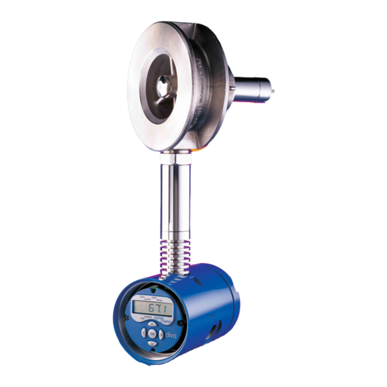
Variable Area (DIVA) flowmeter for use on saturated steam. 2.1 Product description The Spirax Sarco DIVA flowmeter is designed to reduce the cost of flowmetering and is used as an accurate means to measure saturated steam flowrates. The DIVA is a stand alone device and requires no other equipment, such as differential pressure transmitters, pressure sensors, etc. -
Page 4: Technical Data
(130°F) Maximum electronics humidity level 90% RH (non-condensing) Maximum The pressure drop across the DIVA flowmeter at the maximum rated flow PMX differential is nominally 750 m bar (300 inches wg) for the DN50, pressure and 500 m bar (200 inches wg) for the DN80 and DN100... -
Page 5: Dimensions / Weights
2.7 Materials Body Stainless steel S.316 Internals 431 S29 /S303 /S304 /S316 Spring Inconel ® X750 or equivalent Stem Stainless steel 431 S29 Housing Aluminium HE30 2.8 Dimensions /weights (approximate) in mm and kg Size Weight Fig. 2 IM-P337-18 MI Issue 4... -
Page 6: Environmental Conditions
Orientation The DIVA can be installed in any orientation when the pressure is below 11 bar g (160 psi g), see Figures 3 and 4. When the pressure is above 11 bar g the DIVA must be installed in a horizontal pipe, with the electronics housing below the body, see Figure 4. - Page 7 Fig. 3 Vertical flow up to 11 bar g Note: The DIVA operates with flow in one direction only. It is not intended for use with bi-directional flow. The DIVA is clearly marked with a direction of flow arrow.
- Page 8 The DIVA normally only requires a minimum of 6 pipe diameters upstream and 3 downstream of clear straight pipe. These dimensions assume a measurement from a single 90° bend (see Figure 5). 6D Minimum 3D Minimum Fig. 5 Flow If any of the following configurations are present upstream of the DIVA: Two right angled bends in two planes.
- Page 9 See Figure 7. In configurations where there is more than one rapid acting pressure reducing valve close coupled, the DIVA flowmeter should be installed with a minimum of 25 upstream and 3 downstream pipe diameters away from the valves.
- Page 10 Location in pipework Bolt ring gaskets having the same internal diameter of the pipework are recommended. This will prevent possible inaccuracies being created by the gasket protruding into the pipe. Fig. 10 Gaskets fitted incorrectly Fig. 9 Gaskets fitted correctly Fig.
-
Page 11: Electrical Installation
If an M750 display unit is purchased from Spirax Sarco for use with the DIVA, the M750 must be configured to the flow of the DIVA @ 20 mA. If the DIVA 4 - 20 mA output is rescaled (see Section 4.6.1), it is important that the 20 mA input valve on the M750 is also rescaled. -
Page 12: Power Supply Requirements
Power supply requirements A nominal 24 Vdc is needed to power the flowmeter. However, the DIVA will operate correctly as long as the power supply is in the range shown in Figure 14. A single, stand-alone, supply may be capable of powering several transmitters. It can be mounted in a control room or in the field, but cannot be on the same loop. -
Page 13: Run Mode
As all the commissioning settings are stored in a non-volatile memory, it is possible to connect a 9 V PP3 battery to the DIVA's 4 - 20 mA loop power supply and commission the unit uninstalled. However, the DIVA should still be zeroed in-line (see Section 4.5.3) and its operation checked. - Page 14 Kg /h, KW, bar g, °C Imperial lb /h, MBtu /h, psi g, °F The DIVA is factory set to display steam data in metric units and pressing the up or down keys will scroll through the following data. Flow...
-
Page 15: Commissioning Mode
Any data is entered using the OK button. The previously entered selection will flash. After a period of five minutes without any keys being pressed the DIVA will automatically default to the run mode. - Page 16 4.3 DIVA commissioning flow chart Configuration Default = 7452 Software version Flow kg /h or sub-menus but user settable. number lb /h for steam. (test ENTER BASIC xxxxx VER x.x FLOW display) PASS dAtA POWER Power kW or MBtu /h.
- Page 17 xxx% UNItS AtMOS xxx.xx PRES Note: When the dIR sub-menu is entered, HORIZ is HORIZ always shown first. The actual direction selected is the direction which is flashing. xxxxx DOWN ZErO MEtER 4-20 mA SORCE FLOW Sets 4 and 20 mA to an equivalent flowrate or power.
- Page 18 Note: Upon entering the dIR sub-menu, HORIZ is always shown first. The actual direction selected is the one which is flashing. 4.5.2 S/N This is the factory set serial number of the DIVA and is displayed by pressing the right key. IM-P337-18 MI Issue 4...
-
Page 19: Outputs Sub-Menu
4 - 20 mA output. Pressing the right arrow button will display OP = 4 mA and the DIVA will output a steady 4 mA. If the multimeter does not read 4 mA the up and down arrow buttons can be pressed to alter this current until 4 mA exactly is indicated. -
Page 20: Test Sub-Menu
4 - 20 mA output. Pressing the right arrow button will display OP = 20 mA and the DIVA will output a steady 20 mA. If the multimeter does not read 20 mA the up and down arrow buttons can be pressed to alter this current until 20 mA exactly is indicated. -
Page 21: Alarm Sub Menu
HIGH This sub-menu gives access to setting the action that is required on the 4 - 20 mA output when an error is detected by the DIVA electronics. 4.8.1 HIGH If the self-diagnostic electronics determine that the sensor output has been constant for a period of time, or is not giving out a signal, it will set the 4 - 20 mA output to 22 mA. - Page 22 None Echo The response time of the DIVA is less than 0.5 seconds. If the PC asks for data faster than this (i.e. twice per second), the DIVA will answer the first request it received, any later requests will be ignored.
- Page 23 DIVA the flowmeter produces the high turndowns and high accuracy, which are required in process applications. The DIVA should be zeroed using the zero meter sub-menu at least once a year. This will remove any electronic long term drift that may occur. Frequency of re-calibration depends upon the service conditions experienced by the meter and the application.
- Page 24 The DIVA display has in-built diagnostic features and will indicate a number of errors on the display and via the 4- 20 mA output.
- Page 25 Pulse output is overloaded Check load ratings Pulse output electronics Test pulse output. faulty If faulty replace unit. DIVA produces large Upstream /downstream Re-install following the installation amount of noise installation lengths guidelines (Section 3) (banging and clattering) incorrect.
- Page 26 This Table shows all changeable options, and enables records to be made of any changes made to the pass code or other settings. It provides a convenient reference should future changes be required. Changeable Factory set Customer Further Sub-menu settings settings settings changes...
- Page 27 IM-P337-18 MI Issue 4...
- Page 28 IM-P337-18 MI Issue 4...
Need help?
Do you have a question about the DIVA and is the answer not in the manual?
Questions and answers