Table of Contents
Advertisement
1920050/2
IM-P192-02
MI Issue 2
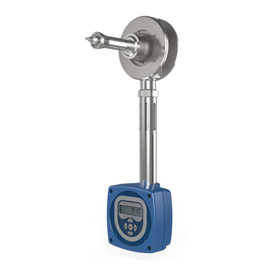
TVA Flowmeter
for Saturated and Superheated Steam Service
Installation and Maintenance Instructions
1. Safety information
2. General product
information
3. Installation
4. Commissioning
5. Maintenance
6. Spare parts
7. Fault finding
8. Settings table
© Copyright 2016
IM-P192-02 MI Issue 2
1
Printed in GB
Advertisement
Table of Contents

Related Manuals for Spirax Sarco TVA Series


Summary of Contents for Spirax Sarco TVA Series
- Page 1 1920050/2 IM-P192-02 MI Issue 2 TVA Flowmeter for Saturated and Superheated Steam Service Installation and Maintenance Instructions 1. Safety information 2. General product information 3. Installation 4. Commissioning 5. Maintenance 6. Spare parts 7. Fault finding 8. Settings table © Copyright 2016 IM-P192-02 MI Issue 2 Printed in GB...
-
Page 2: All Rights Reserved
General installation and safety instructions for pipeline and plant construction, as well as the proper use of tools and safety equipment must also be complied with. Manufacturer:- Spirax Sarco Ltd Charlton House Charlton Kings Cheltenham Glos... -
Page 3: Emc Directive
2004 / 108 / EC. A technical file with a reference number of 'UK Supply TVA flowmeter' supports the Spirax Sarco claim that the product complies with the requirements of the Directive and the product can be used in Class A (heavy industrial) and Class B (domestic / commercial areas). - Page 4 1.9 Tools and consumables Before starting work ensure that you have suitable tools and / or consumables available. Use only genuine Spirax Sarco replacement parts. 1.10 Protective clothing Consider whether you and /or others in the vicinity require any protective clothing to protect against the hazards of, for example, chemicals, high / low temperature, radiation, noise, falling objects, and dangers to eyes and face.
-
Page 5: Residual Hazards
1.16 Returning products Customers and stockists are reminded that under EC Health, Safety and Environment Law, when returning products to Spirax Sarco they must provide information on any hazards and the precautions to be taken due to contamination residues or mechanical damage which may present a health, safety or environmental risk. -
Page 6: General Product Information
Each carton should be unpacked carefully and its contents checked for damage. If it is found that some items have been damaged or are missing, notify Spirax Sarco immediately and provide full details. In addition, damage must be reported to the carrier with a request for their on-site inspection of the damaged item and its shipping carton. - Page 7 Sensor cable Pressure sensor TVA flowmeter body Earth cable ¼" NPSM boss Flowmeter stem Earth 'U' syphon assembly cable Items required for superheat operation Fig. 1 TVA flowmeter Electronics housing IM-P192-02 MI Issue 2...
- Page 8 2.4 Pressure / temperature limits Pressure psi g Steam saturation curve Pressure bar g The product should not be used in this region due to the limitations of the software. Maximum allowable Saturated steam 32 bar g (464 psi g) otherwise as pressure @ 239 °C (462 °F) the specified flange rating Maximum allowable temperature...
- Page 9 High pressure syphon tube assembly Maximum design pressure 80 bar g (1 160 psi g) Maximum design temperature 450 °C (842 °F) Maximum working conditions 60 bar g @ 450 °C (870 bar g @ 842 °F) Pressure sensing kit Maximum operating temperature 125 °C (257 °F)
-
Page 10: Technical Data
2.5 Technical data IP rating IP65 with correct cable glands. Power supply Loop powered nominal 24 Vdc 4-20 mA (proportional to mass flow) Outputs Pulsed output V 28 Vdc, 10 kW, V 0.7 V EIA 232C 15 m limit - See Section 4.12 Communication port RS485 for longer distances (conversion from RS232) - Page 11 2.8 Dimensions/weights (approximate) in mm and kg Size A Flowmeter Weight Superheat syphon DN50 2.67 DN80 4.38 DN100 60 7.28 Note: Dimension 'X' is a recommended minimum distance between the pressure tapping and the flowmeter. However it can be installed at any distance provided the cable allows (Standard cable length is 1 m).
-
Page 12: Installation
3. Installation Note: Before actioning any installation observe the 'Safety information' in Section 1. To meet its specified accuracy and performance it is essential that the following installation guidelines are followed carefully. For steam applications sound steam engineering practices should be followed, including the use of separators. The installation must conform to all relevant construction and electrical codes. -
Page 13: Environmental Conditions
3.1 Environmental conditions The flowmeter should be located in an environment that minimises the effects of heat, vibration, shock and electrical interference. (Pressure / temperature limits are detailed in Section 2.4). CAUTION: Do not lag (insulate) the TVA flowmeter or mating flanges as this may result in excessive temperatures in the electronics. -
Page 14: Mechanical Installation
3.2 Mechanical installation Warning: Do not alter the adjustment nut at the back of the TVA flowmeter shaft, as this will affect the flowmeters calibration. Orientation The TVA flowmeter can be installed in any orientation when used on saturated steam applications and when the pressure is below 7 bar g (101 psi g), see Figures 7, 8 and 9. -
Page 15: Rotating The Electronics Enclosure
Rotating the electronics enclosure Note: The 'U' syphon and pressure sensor must be used for superheated steam The electronics housing can be rotated 270° to applications. enable sufficient clearance for installation. To rotate the electronics housing, loosen the 6 mm grub screw located on the rear of the electronics housing (see Figure 10). - Page 16 Rotating the electronics front panel To rotate the electronics front panel loosen the four retaining screws and rotate the front panel to the orientation, required. Note: Take care not to damage or strain any of the wiring. Retaining screws Retaining screws For applications with For vertical flow applications.
- Page 17 6D Minimum 3D Minimum The TVA flowmeter normally 3D Minimum 6D Minimum only requires a minimum of 6 pipe diameters upstream and 3 downstream of clear straight p i p e . T h e s e d i m e n s i o n s a s s u m e a m e a s u r e m e n t from a single 90°...
- Page 18 Avoid installing the TVA flowmeter downstream of an actuated valve as rapid cycling of the valve could give rise to inaccurate results or damage the flowmeter. See Figure 13. In configurations where there is more than one rapid acting pressure reducing valve close coupled, the TVA flowmeter should be installed with a minimum of 25 upstream and 3 downstream pipe diameters away from the valves.
- Page 19 To install the TVA flowmeter pipeline unit into existing pipework and for aiding possible flowmeter removal, a spool piece can be fabricated locally to the dimensions given below (see Figure 14). Size DN50 DN80 DN100 180 mm 240 mm 300 mm Dimension A 7.1 in 9.5 in...
- Page 20 Location in pipework Bolt ring gaskets having the same internal diameter of the pipework are recommended. This will prevent possible inaccuracies being created by the gasket protruding into the pipe. It is important that the TVA flowmeter is located centrally in the pipework as any eccentricity may cause inaccurate readings.
- Page 21 Fig. 17 Gaskets fitted incorrectly Fig. 18 Gaskets and pipe offline, fitting incorrectly IM-P192-02 MI Issue 2...
- Page 22 3.3 Fitting the pressure sensor for superheated steam applications To operate the TVA flowmeter on superheated steam the pressure sensor must be installed upstream of the actual flowmeter. This is to give full density compensation and allow the amount of superheat to be calculated. A ¼"...
-
Page 23: Electrical Installation
Figure 20. If an M750 display unit is purchased from Spirax Sarco for use with the TVA flowmeter, the M750 must be configured to the flow of the TVA flowmeter @ 20 mA. If the TVA flowmeter 4 - 20 mA output is rescaled (see Section 4.6.1), it is important that the 20 mA input valve... - Page 24 EIA 232 (RS 232) Communication port (RJ11 socket) Superheat pressure sensor pin header connection M750 display unit Pulse Loop with 4-20 mA active input (supplying current loop) 230 V Remote NPN input 50 Hz (maximum 28 V) Power Fuse 1A 0 Volts R ...
- Page 25 Note: Do not reconnect loop power supply to these terminals when RS485 board fitted. Power supply 24 Vdc (19 - 28v) 50 mA maximum GND data B - data A + data Fig. 21 TVA with EIA 485 (RS485) Communications wiring diagram IM-P192-02 MI Issue 2...
-
Page 26: Power Supply Requirements
Power supply requirements A nominal 24 Vdc is needed to power the flowmeter. However, the TVA flowmeter will operate correctly as long as the power supply is in the range shown in Figure 20. A single, stand- alone, supply may be capable of powering several transmitters. It can be mounted in a control room or in the field, but cannot be on the same loop. -
Page 27: Rotating The Display
4. Commissioning After all mechanical and electrical work has been c ompleted, the following commissioning instructions should be followed. The TVA flowmeter should be commissioned with the f l o w t h r o u g h t h e u n i t display isolated. - Page 28 4.1.1 Run mode data sequence Total High kg or lb Total Low kg or lb Flow POWER Power kW or kBtu/h. Pressure bar g or psi g, depending if Pressure metric or imperial units are selected. Temperature °C or °F. Temp.
- Page 29 4.1.2 Error display messages Any errors that occur will be displayed in the run mode. The errors will alternate with the normal run mode display and will be prioritised. The errors will be latched and can only be cancelled by pressing the 'OK' button. Once the error message has been cancelled the display will show the next (if any) error.
-
Page 30: Commissioning Mode
4.2 Commissioning mode The commissioning mode is used to zero the flowmeter, re-range, enable the pressure sensor (for superheat applications), set and test the outputs and change the pass code. All data entry is performed via a menu and sub menu configuration with the key pad buttons used for navigation, i.e. - Page 31 To exit from the commissioning mode at any stage, continually pressing the left key will return to the run mode. Pressing the up and down buttons scrolls through the various first level menus. Pressing the right arrow button enters a particular sub-menu. ENtER bASIC 8888...
- Page 32 4.3 TVA flowmeter commissioning flow chart Software Normal run mode Default = 8888 Configuration version number display sequence sub-menus but user settable. Total (test ENtER bASIC 8888 VER x.x display) high dAtA PASS Power on sequence; turn on all segments, then kg or lb Total show the software version...
- Page 33 xxx% UNItS tOtAL MASS ENERGy AtMOS xxx.xx PRES HORIZ dOWN CLEAR tOtAL xxxxx ZERO MEtER 4-20 mA SORCE FLOW POWER PULSE SORCE tOtAL SEt4 mA xxxxx ENRGy in kg /h or lb /h, kW or kBtu /h. NUM / xxxxx SEt20 mA xxxxx PULSE...
- Page 34 4.4 bASIC DAtA Sub menu bASIC xxx% dAtA UNItS MASS tOtAL ENERGy AtMOS xxx.xx PRES 4.4.1 dRy Pressing the right key will display the dryness fraction. This is the dryness fraction of the saturated steam being measured. This can then be edited to suit the application. Press the 'OK' button to confirm the selection.
- Page 35 4.5 MEtER Sub-menu HORIZ MEtER xxxxx DOWN This sub-menu contains information about the flowmeter and is used to zero the ZErO MEtER flowmeter and clear the total. CLEAR tOtAL 4.5.1 dIR dIR is the orientation that the TVA flowmeter is installed in. The TVA flowmeter can be installed with horizontal flow up to a pressure of 32 bar g (464 psi g).
- Page 36 4.6 OutPutS Sub-menu This sub-menu allows both the 4-20 mA and pulsed 4-20mA outputs of the flowmeter to be configured. PUtS PULSE 4.6.1 4-20 mA Output sub-menu 4-20 mA SORCE FLOW PUtS POWER SEt4 mA XXXX The 4-20 mA sub-menu allows re-ranging and re-calibrating of XXXX SEt20 mA...
- Page 37 4.6.7 Pulse Output This sub-menu allows the pulsed output to be configured. PULSE SORCE tOtAL ENRGy NUM/ xxxxx PULSE 4.6.8 PULSE This selects whether the pulsed output is to be used or disabled. PULSE xxxmS WIDTH 4.6.9 SORCE This selects the source data for the pulsed output. The source data can be either unit mass per pulse (tOtAL) or unit energy per pulse (ENRGy).
- Page 38 4.7 PRES SENSR sub-menu PRES 0CAL XXXXX SENSR 25CAL XXXXX SH MARGN LIMIt PRES ALARM ALARM dELAy Selecting 'YES' at the PRES SENSR menu will enable the pressure sensor option. 4.7.1 0CAL When the pressure sensor has been enabled, the 0CAL menu will be displayed. Pressing the right arrow key (>) will display the 0CAL bits values.
-
Page 39: Test Sub-Menu
4.8 tESt sub-menu The tESt sub-menu allows access to the TVA flowmeter's diagnostic tools. From here the display, 4-20 mA and pulse outputs can be tested. tESt dISP 4-20mA xxx.xxmA PULSE CANCL 4.8.1 dISP This allows the display to be tested. Pressing the right button will cause all the segments on the display to be turned on. -
Page 40: Alarm Sub-Menu
4.9 ALARM sub-menu This sub-menu gives access to setting the action that is required on the 4-20 mA output when an error is detected by the TVA flowmeter electronics. It also gives access to the power alarm function. HIGH ALARM ALARM POWER ALARM... - Page 41 4.9.3 CONSt ALARM This allows the constant flow alarm to be turned off. The constant alarm is switched to on by the default factory setting. It detects if the flow has been constant for long periods when at pressure, which may indicate a stuck cone due to debris.
- Page 42 4.12 TVA communications 4.12.1 TVA UART set-up The TVA flowmeter has an EIA 232C compatible communications link and supports two protocols: a simple Line Feed [LF] terminated ASCII protocol and a subset of Modbus/RTU. This enables users to easily interrogate the TVA flowmeter for steam data using either a dumb terminal or a P.C.
-
Page 43: Ascii Communications
The communications protocol has been set up on the communicating device as described earlier in this Section. The following is a Table of operating codes in ASCII characters:- ASCII communications Please note that all the following commands are case sensitive… User transmits TVA responds (metric) TVA responds (imperial) -
Page 44: Modbus Communications
4.14 Modbus communications The TVA flowmeter has Modbus communications, in addition to the ASCII Modbus comms that are available through the TVA RS232 port. An RS485 to RS232 converter is required, or alternatively, an Ethernet to RS232 converter, both of which are widely available. Modbus comms protocol Format: Request frame Address... - Page 45 Register Modbus Parameter Received Units Notes number address data scale Total = (Total high x 40001 Total low 16 bits 65536) + Total low * 40002 Total high 16 bits 40003 Flow Kg/h 40004 Pressure x100 BarG 40005 Temperature °C Water equivalent 40006 L/hour...
- Page 46 4.14.2 Alarm status register bit-fields: Bit 1 Bit 0 State Alarm code Superheat 0x0000 Not applicable Not applicable Saturated 0x0002 Sub-saturated 0x0003 Set (1) Cleared (0) Pressure alarm is active Bit 2 (0x0004) Pressure alarm is idle (too high or too low) Bit 3 (0x0008) Superheat margin active Superheat margin idle...
-
Page 47: Maintenance
Important note: The TVA is a loop powered device. It requires the CTS and DTR terminals to be wired and enabled to power the communications interface. Failure to do so will prevent the communications working. 4.14.3 Response time: The TVA will start responding within 500 msec. The actual time to fully receive a response from the TVA is baud rate dependent, for example a Modbus poll of 12 registers @1200 baud rate could take ((5 + 24) bytes x ~10 ms / byte) + 500 ms ≈... -
Page 48: Spare Parts
6. Spare parts 1. Spare electronics for the TVA flowmeter are available from Spirax Sarco and consist of: TVA flowmeter replacement display and electronics with front housing. State if RS485 board is fitted. It is important that the serial number of the TVA flowmeter is given at the time of ordering. -
Page 49: Fault Finding
7. Fault finding Many faults which occur on commissioning are found to be due to incorrect wiring or setting up, therefore it is recommended that a thorough check is carried out should there be a problem. The TVA flowmeter display has in-built diagnostic features and will indicate a number of errors on the display and via the 4-20 mA output. - Page 50 Symptom Possible cause Action Constant 3.8 mA Error signal set to Low. Check display for errors and rectify as above. Check current output electronics (refer to Sections 4.6, 4.7 and 4.8). Constant 22 mA Error signal set to High. Check display for errors and rectify as above.
- Page 51 Symptom Possible cause Action TVA produces Upstream/downstream Re-install following the installation large amount of installation lengths guidelines (Section 3). noise (banging and incorrect. clattering) Non zero flow Unit not zeroed at Zero unit. indicated when no commissioning. actual flow is in the pipe.
-
Page 52: Settings Table
8. Settings table This Table shows all changeable options, and enables records to be made of any changes made to the pass code or other settings. It provides a convenient reference should future changes be required. Changeable Factory Customer Further Sub-menu settings settings...
Need help?
Do you have a question about the TVA Series and is the answer not in the manual?
Questions and answers