Table of Contents
Advertisement
Quick Links
1980050/5
Rotor Insertion Flowmeters
Installation and Maintenance Instructions
RIM10-600
RIM10-700
IM-P198-02 MI Issue 5
RIM10 Series
RIM10-900
IM-P198-02
1. Safety information
2. General product
information and Guide
to installation
3. Mechanical installation
4. Electrical installation
5. Configurating your
flowmeter
6. RIM10 Series web
interface
7. MODBUS
8. Diagnostics and
Calibration
9. Maintenance and
Troubleshooting
© Copyright 2013
Printed in the USA
MI Issue 5
1
Advertisement
Table of Contents

Subscribe to Our Youtube Channel
Related Manuals for Spirax Sarco RIM10 Series


Summary of Contents for Spirax Sarco RIM10 Series
- Page 1 1. Safety information 2. General product information and Guide to installation 3. Mechanical installation RIM10-600 4. Electrical installation 5. Configurating your flowmeter 6. RIM10 Series web interface 7. MODBUS 8. Diagnostics and Calibration 9. Maintenance and Troubleshooting RIM10-700 RIM10-900 © Copyright 2013...
- Page 2 IM-P198-02 MI Issue 5...
-
Page 3: Safety Information
1. Safety information Safe operation of these units can only be guaranteed if they are properly installed, commissioned and maintained by a qualified person in compliance with the operating instructions. General installation and safety instructions for pipeline and plant construction, as well as the proper use of tools and safety equipment must also be complied with. - Page 4 The symbols, used on the product and in this manual, mean: Equipment protected throughout by double insulation or reinforced insulation. Functional earth (ground) terminal, to enable the product to function correctly. Not used to provide electrical safety. Caution, risk of electric shock. Caution, risk of danger, refer to accompanying documentation.
-
Page 5: Pressure Systems
1.9 Tools and consumables Before starting work ensure that you have suitable tools and / or consumables available. Use only genuine Spirax Sarco replacement parts. 1.10 Protective clothing Consider whether you and / or others in the vicinity require any protective clothing to protect against the hazards of, for example, chemicals, high / low temperature, radiation, noise, falling objects, and dangers to eyes and face. -
Page 6: Returning Products
1.11 Permits to work All work must be carried out or be supervised by a suitably competent person. Installation and operating personnel should be trained in the correct use of the product according to the Installation and Maintenance Instructions. Where a formal 'permit to work' system is in force it must be complied with. -
Page 7: Product Description
Copyright © Spirax Sarco, Inc.(2010) All rights reserved. Spirax Sarco, Inc. grants the legal user of this product (or device) the right to use the Work(s) solely within the scope of the legitimate operation of the product (or device). No other right is granted under this license. In particular and without prejudice to the... - Page 8 If non-vertical mounting is required, the deviation from vertical should not exceed 90°. If mounted beyond 90°, the isolation valve may trap steam or hazardous chemicals, presenting a danger to persons servicing the RIM10 Series of rotor insertion flowmeters. These flowmeters should always be self-draining.
- Page 9 2.5 Installation guidelines D = Pipe diameter Choosing correct installation Please note that the straight run of location for the RIM10 involves several pipe must have the same nominal important considerations: diameter as the flowmeter body. Ambient temperature limit electronics designed function in a maximum continuous 10 x D...
- Page 10 2.6 Flowmeter location The RIM10 Series can be mounted in either horizontal or vertical piping runs - See Figure 3. It is important for the pipe to be full for accurate measurements. Follow the guidelines below for the recommended location for installation:...
-
Page 11: Mechanical Installation
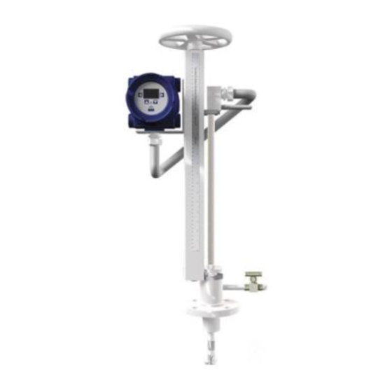
3. Mechanical installation 3.1 Pipe tapping The pipeline should be prepared for either cold tap or hot tap installations. A cold tap installation involves drilling a hole into a pipeline that has been depressurised and for which service has been shutdown. A hot tap installation involves drilling a hole into a pressurised line without line shutdown and disruption of the process. - Page 12 Use Steps 1 to 5 as a guide. Wheel Fig. 6 RIM10-600 Bleed valve Scale reading Bronze Bleed isolation valve valve Pipe nipple Thread-o-let Ball Gate valve Weld-o-let Fig. 7 RIM10-900 Both the Ball and Gate valve are available from Spirax Sarco IM-P198-02 MI Issue 5...
- Page 13 Step 1 - Weld thread-o-let RIM10-600 or weld-o-let RIM10-900. Step 2 - For the 2" RIM10-600 series, thread the pipe nipple into the thread-o-let and hand tighten. For the DN50 RIM10-900 series, weld the nipple to the weld-o-let, welding the flange to the nipple. Step 3 - Connect the isolation valve: Attach the hot tap tool.
- Page 14 3.2.2 Cold tap installation Caution - Risk of danger: Cold tap installation must only be done by qualified personnel. Process shutdown and line depressurisation are required for cold tap installation. Use Steps 1 to 4 below as a guide. Bleed valve Bronze isolation valve Pipe nipple Thread-o-let...
- Page 15 3.2.3 Insertion depth scale reading calculation After tapping the pipe and installing the RIM10 flowmeter, the turbine sensor needs to be properly positioned within the pipe. To determine the proper insertion depth, the scale reading must be calculated. The scale reading is the figure that the top of the cursor should be set to on the depth scale.
- Page 16 3.2.4 Rotor orientation and final positioning Note: Tighten the nuts above the packing gland to 34 N m (25 lbf ft) to stop leakage around the stem. Do not over tighten! Caution: Do not allow the orientation of the flowmeter or the insertion depth to change after insertion is complete.
- Page 17 3.2.5 Rotor orientation and final positioning Use the retractor handle to carefully insert the rotor down into the pipe until the calculated insertion depth figure on the depth scale lines up with the top of the cursor. Use a pipe wrench to align the retractor bar assembly so the flow direction arrow on the cursor is in line with the pipe and pointed downstream.
- Page 18 3.3 RIM10-700 cold tap installation The RIM10-700 is non-retractable and must be cold tapped. Process shutdown and line depressurisation are required for cold tapping. There are two mounting connections available: Flanged or Screwed. 3.3.1 Installation for flanged connections: Step 1 - Tap the pipe, the hole should be at least 50 mm (2") in diameter, nominally 50 mm (2") in diameter.
- Page 19 3.3.2 Installation for screwed connections: Step 1 - Tap the pipe, the hole should be at least 50 mm (2") in diameter, nominally 50 mm (2") in diameter. Step 2 - Weld thread-o-let to pipe. Step 3 - Important - Attach the tap check tool to the end of the flowmeter stem before proceeding: Attach the flowmeter to the thread-o-let.
- Page 20 3.3.3 Insertion depth measurement calculation for the RIM10-700 Use the following equation to calculate the insertion depth for the RIM10-700: B = C – I – E – Wt Where: = Installed dimension to be set on the flowmeter. = For G6 rotor 362 mm (14.25") For L1 and G1 to G5 rotors 368 mm (14.50") = For pipe sizes less than 300 mm (12"), inside pipe diameter ÷...
- Page 21 3.3.4 Rotor orientation and final positioning Caution: Do not force the stem into the pipe. If the stem insertion is blocked, retract and remove the flowmeter from the pipeline, checking to make sure the opening conforms with the guidelines listed in the mounting guidelines. Manually insert the stem into the pipe until the calculated insertion depth is obtained.
-
Page 22: Electrical Installation
- Virtual front panel display and set-up wizard using Internet Explorer 6.0 or later on a standard PC The electronics within the RIM10 Series rotor insertion flowmeters are housed in a cast aluminum condulet housing. The condulet is rated for Class I, Div II environments. All field wiring to the flowmeter is connected to the terminal blocks and RJ-45 network port located beneath the rear screw cover (opposite end to the display). -
Page 23: Ground Loops
4.1.1 Ground loops Ground loops may interfere with signal transmission by superimposing unwanted signals on the desired signals. This may be prevented by correctly connecting the cable shields. Metal or plastic pipelines determine the shield to be used. Metal pipelines are usually earth grounded. Thus, the cable shield should not be connected at the flowmeter. - Page 24 4.2 Wiring the flowmeter CONN 2 RS485 RS485 + RS485 + CONN 1 GND_5VISO Ethernet RS485- RS485- 1 TX + 2 TX - 3 RX + 6 RX - CONN3 Remote head C1_SENSE_IN - C1_SENSE_IN + C1_SHIELD_DRV C2_SHIELD_DRV C2_SENSE_IN - Conn1 C2_SENSE_IN + RTD_COMP...
-
Page 25: Pulse Output
4.2.1 dc power Wire the dc power as shown in Figure 20 using 0.82 mm - 0.33 mm (18 - 22 AWG) gauge wire. The dc supply can be anywhere from 12 - 32 V, but 24 V is recommended. On installation the RIM10 shall be provided with supply transient protection external to the apparatus such that the voltage at the supply terminals of the RIM10 does not exceed 140% of the voltage rating of the equipment. - Page 26 4.2.3 External 4-20 mA current loop output Three output channels are available for connection. These are 2-wire current loop connections. The positive side is connected to the 24 Vdc supply at pin 7. The negative side is connected to the 4-20 mA receiver input terminal. The receiver should have the common or ground terminal connected to the power supply ground as shown in Figure 22.
- Page 27 4.2.5 4-20 mA current loop multiple inputs and outputs It is not altogether obvious how to wire multiple 4-20 mA current loops without inserting too many wires into the 24 V and GND terminals. One technique is shown in the following wiring diagram - Figure 24, which depicts the worst case, which is 3 inputs and 3 outputs at the same time.
-
Page 28: Relay Output
4.2.6 Relay output There are 2 single pole double throw relays available. Each has a normally-closed and normally-open contact which can be wired as shown in Figures 25 and 26. These relays provide resistance of 35 ohms maximum and switching times of less than 1 millisecond. They are limited to 120 mA of current and 350 V blocking voltage. - Page 29 4.2.7 RS485 communications A single 2-wire RS485 half-duplex communications channel is provided, and can be used as a Modbus RTU. Wiring is as shown in Figure 27. Caution: Please note that EIA standard 'B' and 'A' terminal labels are used, which are opposite those used by some transceiver manufacturers (for example, Texas Instruments), so care must be taken to not invert the polarity of the signal wires.
-
Page 30: Remote Mount Option
4.3 Remote mount option The remote mount option allows the main RIM10 electronics to be mounted at a distance from the RIM10 flowmeter at the pipe. The main electronics may be separated from the flowmeter by up to 30.5 m (100 ft) of wiring. Standard shielded twisted-pair cable (Category 5, 5e or 6) is recommended. -
Page 31: Wiring Notes
Fig. 29 RIM10 remote mount PCBA Wiring notes: 1. Use twisted wire for the wire pair C1_SENSE_IN- (P3 Terminal 1) and C1_SENSE_IN+ (P3 Terminal 2). 2. Use twisted wire for the wire pair C2_SENSE_IN- (P3 Terminal 5) and C2_SENSE_IN+ (P3 Terminal 6). 3. -
Page 32: General Information
Fig. 30 5.1 General information The RIM10 Series can be configured through the front panel menu system. The front panel consists of an LCD and 5 button magnetic keypad. It also has an LED backlight to improve visibility in dim environments. The keypad buttons are actuated only by the presence of a magnetic field. -
Page 33: Run Mode
Pressure Parameter name 34.45 Numeric value Units Fig. 31 The user can select which screens are displayed from a menu when in Programming mode. RIM10 Series Right arrow key Density Right arrow key Parameter name Firmware version 0.256 Numeric value Lb / ft Ù... -
Page 34: Program Mode
5.3 Program mode To enter Program mode, the user must hold the magnetic wand over the Enter key for at least 5 seconds. When the unit enters program mode, the Main menu will appear. In Program mode, there are two different types of displays. The first type is a scrollable list of selectable menu items - See Figure 33. - Page 35 5.4 Data edit screen example This sequence from the set-up wizard menu, shows in detail, the steps required to change the pipe inside diameter using the keypad - See the 'Data edit screen example' Figure 35. PIpe Inside Diameter P r e s s i n g t h e e n t e r key when the left arrow symbol 3.068 in is selected returns to the...
-
Page 36: Reset Totalizers
5.5 Program mode menus The Main menu is the first menu in Programming Mode - see Main Menu Figure 36. To access one of the sub-menus, select the menu using the up or down arrow keys and then press the enter key Return to Display or right arrow key. -
Page 37: Reset Min / Max
5.7 Reset min / max This menu (Figure 38) lets the user view and / o r clear the minimum / m aximum parameters. The user can reset all simultaneously or individually. The example below shows clearing the minimum and maximum temperature values for the first temperature sensor. The Clear Temp 1 Min / ... - Page 38 5.8 Display set-up (screen selection menu) - Figure 39 This menu has 3 sub-menus: Screens On / Off, Display Units, and LCD set-up. Screens On / Off lets the user select which parameter screens they want to see during Run mode. Display Units lets the user configure different output units.
- Page 39 5.9 Display set-up (LCD set-up menu) LCD set-up lets the user adjust the display time delay, contrast, and backlight brightness. Main Menu Set-up Display Return to Display Screens On / Off Reset Totalisers Display Unit Reset Min / Max LCD Set-up Display Set-up Enter / right Set-up Wizard...
- Page 40 5.10 Display set-up (display units menu) Display units lets the user configure different output units. Main Menu Return to Display Note: Reset Totalisers Use the up / down keys Reset Min / Max to select the Display Set-up desired units Set-up Wizard Network Set-up SELECT...
- Page 41 5.11 Set-up wizard (general settings) This menu (Figure 42) assists the user in setting up the flowmeter. A series of screens guides the user through set-up of the flowmeter measurement type, input and output sensor configuration, relay alarms, pulse output, and totalizer assignments. Main Menu Tag number 1734.456...
- Page 42 5.12 Set-up wizard (frequency / velocity calibration data) If the user needs to install a new RIM10, this menu is where the new frequency / velocity calibration data is entered - See Figure 43. From page 41 If no changes Edit frequency / selected Select curve fit...
- Page 43 5.13 Set-up wizard (measurement type) This menu (Figure 44) lets the user select the type of measurement and configure the sensor inputs. Measurement type Select temp sensor Enter 4-20 mA input for density minimum temperature Steam Volume measurement Steam Controlled 32.5 F Steam Saturated Temp # 1 input...
- Page 44 5.14 Set-up wizard (totalizer assignment) This menu (Figure 45) lets the user configure the 2 totalizers. From page 43 To page 45 None Totaliser # 1 assignment None Volume flow Comp flow Mass flow Energy flow Totaliser # 2 Enter / right assignment arrow None...
- Page 45 5.15 Set-up wizard (analog outputs) This menu (Figure 46) lets the user configure the three analog outputs. page None Configure outputs No changes Analog out # 1 Analog out # 2 Analog # 3 Enter / right arrow Select parameter None Temperature Temperature _2...
- Page 46 5.16 Set-up wizard (relay 1 alarm) This menu (Figure 47) lets the user configure Relay 1 alarms. From page 45 To page 47 None Relay # 1 None Temp # 1 alarm Temp # 2 alarm Diff temp alarm Pressure alarm Density alarm Velocity alarm Volume flow alarm...
- Page 47 5.17 Set-up wizard (relay 2 alarm) This menu (Figure 48) lets the user configure Relay 2 alarms. To page 48 None Relay # 2 None Temp # 1 alarm Temp # 2 alarm Diff temp alarm Pressure alarm Density alarm Velocity alarm Volume flow alarm Comp flow alarm...
- Page 48 5.18 Set-up wizard 5.19 Set-up wizard (pulse output frequency) (pulse output totalizers) This menu (Figure 49) lets the user This menu (Figure 50) lets the user configure the pulse output. configure the pulse output. From page 47 Set Pulse output func Set Pulse output func Scaled freq Scaled freq...
- Page 49 5.20 Set-up network (ModBus RTU) This menu lets the user set the Modbus or Ethernet parameters. Two ModBus interfaces are available: RTU or TCP. The menu below (Figure 51) shows the RTU set-up. Main Menu Set Baud rate Return to Display Reset Totalisers 1200 Reset Min / Max...
- Page 50 5.21 Set-up network (Modbus TCP) This menu (Figure 52) shows the TCP Modbus menu. Main Menu Return to Display Reset Totalisers Reset Min / Max Display Set-up Set-up Wizard Network Set-up Set Time / Date Faults Service Enter / right arrow Set-up network ModBus...
- Page 51 5.22 Set-up network (Ethernet) This menu (Figure 53) lets the user enter Ethernet parameters. Main Menu Return to Display Reset Totalisers Reset Min / Max Display Set-up Set-up Wizard Network Set-up Set Time / Date Faults Service Enter IP address Enter / right arrow 192.168.001.001...
- Page 52 5.23 Set time / d ate This menu (Figure 54) lets the user adjust the month, date, year, and local time. Main Menu Return to Display Reset Totalisers Reset Min / Max Display Set-up Set-up Wizard Network Set-up Set Time / Date Faults Service Enter / right...
- Page 53 5.24 Faults This menu (Figure 55) lets the user view and / o r clear the flowmeter faults. Each fault has a code number and a message that describes the details of the fault. A list of faults is stored in the memory.
- Page 54 5.25 Service (calibrate 4-20 mA input / output) This menu (Figure 56) lets the user calibrate the three 4-20 mA input and output channels. It requires the user to use an external ammeter to measure the calibration current. See the Section on calibrating Analog Input and Output - page 84.
- Page 55 5.26 Service (reset password) This menu lets the user change the 6-digit password, perform analog input / output calibration, test the relay and pulse outputs, and clear the non-resetable totalizers via the factory password. The sequence shown in Figure 57 illustrates how to change the password.
- Page 56 5.27 Service 5.28 Service (outputs test) (factory settings) This menu (Figure 58) lets the user This menu (Figure 59) lets a qualified test the 2 relay alarms and the pulse service technician reset the non- output. resetable totalizers. Main Menu Main Menu Return to Display Return to Display...
- Page 57 6. RIM10 series web interface 6.1 General information The web interface is designed to easily lead the user through a variety of options to set-up the RIM10 system, using easy to navigate menus and drop down lists - See Figure 60.
- Page 58 There are two options for viewing: Show All Values, which shows all inputs and outputs. Main Menu, which provides detailed set-up information and options for network, configuration and display. Fig. 61 From the Main Menu screen, the user can view the current settings or use the buttons on the right to reconfigure various aspects of the system.
-
Page 59: Setup Wizard
6.2 Set-up wizard Click the Set-up Wizard button to enter the set-up configuration series of screens. The first screen is Configuration Load Options - Figure 62. This function is only available on the web interface. Fig. 62 Configuration load options This page begins the set-up process. - Page 60 Step 2: Flowmeter - This is where all identifying information for the flowmeter is entered. If any of this data is incorrect, click on the Edit button and you will be guided through the various flowmeter data screens. • Meter Label •...
- Page 61 You will be returned to the main Flowmeter Set-up screen once you have cycled through the set-up screens listed above. Step 3: Measurement – The type of product to be measured with accompanying values are edited on this screen. Fig. 65 Select a measurement type: Steam volume Steam controlled...
- Page 62 Step 4: Inputs: Values selected in measurement affect the display for inputs. Depending on what you put in, you may be asked to choose the following: Pressure from 4-20 mA channel 3 input or substitute Temperature from internal RTD, 4-20 mA channel 1 or 4-20 mA channel 2 For 4-20 mA values, enter the minimum and maximum units.
- Page 63 Then, select the units. For Volume and Comp flow: Feet cubed Inches cubed Gallons Liters Meters cubed Quarts For Mass flow: Pounds Tons Grams Kilograms Metric tons For Energy flow: Kcal Mcal Edit the totalizer scale factor for the measurement selected. Repeat process for Totalizer 2. For Analog Outputs 1-3: Select an analog output parameter: None...
- Page 64 For Relays 1 and 2: Select a configuration: None Temperature number 1 alarm Temperature number 2 alarm Differential temperature alarm Pressure alarm Density alarm Velocity alarm Volume flow alarm Comp flow alarm Mass flow alarm Energy alarm Select a limit: High Window Edit hysteresis value.
-
Page 65: Display Setup
Fig. 66 If all are correct, click the Save button again to return to the Main Menu screen. 6.3 Display set-up Click the Display Set-up button to go to the Display Configuration Menu, where you can choose the parameters you wish to see on the Operating Display screen. Check the box beside each value you wish to have displayed on start-up, then click the Save Changes button. -
Page 66: Network Setup
6.4 Network set-up To set-up a network connection, select Network Set-up from the Main Menu of the RIM10 web interface. The web interface configures the network settings for the RIM10 flowmeter. Select either Ethernet (Section 6.4.1) or Modbus Network (Section 6.4.2). Fig. -
Page 67: Step 2. Current Ip Address
Step 1. Hostname The Current Hostname is displayed. To enter a new hostname, type the name in the New Hostname box. To select a new domain, type the new domain name in the box displayed. Click on Next to move to Step 2. Step 2. -
Page 68: Step 1. Unit Number
6.4.2 Modbus network set-up wizard The Modbus connection wizard is completed in two steps: Unit number Comm parameters After selecting the Modbus Network, the following screen appears. Fig. 74 Select Next to change the current settings. Select Main Menu to cancel and return to the Main Menu. Step 1. -
Page 69: Step 2. Communication Parameters
Step 2. Communication parameters Enter the following: New baud rate New number of bits New stop bits New parity Select Finish to move to the next screen. Fig. 76 To save the changes entered, select Save. You will now be returned to the Main Menu. Or, you can click on the Main Menu button to cancel changes and return to the Main Menu screen. - Page 70 6.5 Time set-up Fig. 78 6.6 Reset Totalizers Fig. 79 6.7 Reset Min/Max Fig. 80 6.8 Service For user of the service options in the RIM10 web interface refer to Section 8 'Diagnostics and Calibration' and Section 9 'Troubleshooting and Maintenance'. Fig.
- Page 71 6.8.1 Service (Loop Calibration) This following will assist the user to calibrate each of the 4-20 mA input or output current loops. Use example: calibrate 4-20 mA input channel 1 - See section on Calibration of Analog Input and Output: page 82. Step 1 Take the flowmeter 'offline' by clicking the Go Offline button.
- Page 72 6.8.2 Service (RIM10 calibration) The following will assist the user in entering frequency / velocity data for a calibrated RIM10. Note: this data should not be changed unless the user is replacing a damaged RIM10 and has new calibration data from EMCO. Fig.
- Page 73 6.8.3 Service (configure data log) The following will assist the user in selecting and saving the flowmeter parameters to the log file and how often to save the data. Note: Clicking on the Clear Log button will permanently erase the Log file. Fig.
-
Page 74: Read Operation
The Modbus implementation for the RIM10 Series allows the user to view and modify flowmeter parameters. Appendix A lists the available Modbus registers. Modbus uses a Master / Slave communication scheme. - Page 75 Modbus RTU read example: Read float123.456 from holding register 40984. Command: (from Master) Field name Hex value Slave address Function Address byte Hi Address byte Lo Bytes to read Hi byte Bytes to read Lo byte CRC Hi byte CRC Lo byte Response: (from RIM10) Field name Hex value...
-
Page 76: Appendix A - Modbus Register Table (Rev 3)
Appendix A - Modbus Register Table (rev 3) Parameter Register Type Bytes Description Flowmeter Name 4101 char The flowmeter name, identifier Flowmeter Serial 4242 char Flowmeter unique serial number Number Alarm relay #1 12400 short Relay output status 1 = on / c losed status Alarm relay #2 12401... - Page 77 Parameter Register Type Bytes Description Compensated 41006 float Temperature compensated vol flow, cfm Volume flow Mass flow 41008 float Mass flow, lb/min Energy flow 41010 float Energy flow, Btu/min Density 41018 float Density, lb/cu ft Viscosity 41030 float Fluid viscosity, centipoise Pressure 40992 float...
-
Page 78: Appendix B - Web Page Screen Shots
Appendix B - Web page screen shots Fig. 86 Fig. 87 Fig. 88 IM-P198-02 MI Issue 5... -
Page 79: General Information
8. Diagnostics and Calibration 8.1 General information The RIM10 system self-checks its internal status every 500 ms (1/2 second). If there is a problem with any part of the system, the yellow fault light will appear on the flowmeter front panel and the main web page screen will show a fault message. - Page 80 4. The report page is a condensed text display of all internal settings. To view an output or input report, click on the Report button in the Operations line. Fig. 91 5. The Data Log page shows a list of selected flow parameters that are saved to flash memory at selected intervals.
-
Page 81: History Data Log
8.3 History Data Log Fig. 93 The Fault event log is a time-stamped listing of faults or significant changes in the flowmeter settings. The state shows fault / event activity. 'A' means a fault has been added to the list. 'C' means an existing fault is cleared. - Page 82 8.4 Flowmeter faults menu When the fault LED turns on, details of the problem can be viewed using the LCD interface: 1. Hold the magnet over the Enter button for five seconds to enter programming mode. 2. Using the magnet with the down arrow, scroll to the Fault line item. When selected, a screen will appear displaying how many faults there are.
- Page 83 Error Code Description Failed to open internal drivers, flowmeter is not functional Watchdog Flowmeter running factory settings, not user configured Unable to load configuration file, using built-in defaults Flowmeter configuration changed Min / Max temperature 1 changed Min / Max temperature 2 changed Min / Max pressure changed Min / Max volume flow changed Min / Max compensated volume flow changed...
-
Page 84: Output Calibration
8.5 Calibrating Analog Input and Output in the LCD Calibration of analog input and output from the LCD interface is done through the Service menu. To get to the Service menu: 1. Go into programming mode by holding the magnet over the Enter button for approximately five seconds. -
Page 85: Input Calibration
15. Select Edit in the navigation bar to enter the edit mode. The cursor will blink over the last number. 16. Use the left and right arrow keys to move around within the number displayed. Use the top and bottom arrow keys to increase or decrease each number until it is set to the correct mA. -
Page 86: Maintenance And Troubleshooting
As a result, the rotor spins unevenly or does not spin at all. To demagnetize a rotor, return the rotor to Spirax Sarco, for service. 7. Contact your sales representative. - Page 87 9.4 Analog output less than 4 mA 1. Verify wiring is in accordance with the power and wiring diagrams in Section 4 'Electrical installation'. 2. Check the power supply voltage. 3. Check the voltage at the flowmeter. 4. Verify the analog zero and span calibration. 5.
- Page 88 9.5 Inaccurate output 1. Verify the piping installation has allowed for the required straight pipe run. See Section 2.4 2. Verify flow is within the range of the rotor. See Figure 96. Fig. 96 Where: V max = maximum velocity of fluid [ft/sec (m/sec)] V lin = minimum velocity of fluid at which rotor response is linear [ft/sec (m/sec)] V min = minimum measurable velocity of fluid [ft/sec (m/sec)] r = density of fluid [lbs/ft 3 (kg/m)]...
- Page 89 9.9 Magnetized rotor A rotor with residual magnetism produces an erratic signal, which will appear as if a high frequency signal has been combined with a longer, lower frequency signal. 9.10 Overranged flowmeter Excessive flow velocity can cause the rotor to overspeed. The sine wave of an over-ranged rotor looks as if several sine waves were superimposed on each other each wave slightly offset from the other.
- Page 90 IM-P198-02 MI Issue 5...
- Page 91 IM-P198-02 MI Issue 5...
- Page 92 IM-P198-02 MI Issue 5...
Need help?
Do you have a question about the RIM10 Series and is the answer not in the manual?
Questions and answers