Table of Contents
Advertisement
Quick Links
Advertisement
Table of Contents

Related Manuals for Arcteq AQ-V251


Summary of Contents for Arcteq AQ-V251
- Page 1 AQ-V251 Voltage protection device Instruction manual...
-
Page 2: Table Of Contents
3.2 Configuring user levels and their passwords................. 12 4 Functions unctions ...................................................... 14 4.1 Functions included in AQ-V251.................... 14 4.2 Measurements........................15 4.2.1 Voltage measurement and scaling ................15 4.2.2 Voltage memory ......................28 4.2.3 Frequency tracking and scaling ................. 31 4.3 General menu........................ - Page 3 6 Connections and applic 6 Connections and applica a tion examples tion examples..................................243 6.1 Connections of AQ-V251....................243 6.2 Application example and its connections................245 6.3 Trip circuit supervision (95) ....................246 7 Construction and installa 7 Construction and installation tion ....................
- Page 4 8.3 Tests and environmental ....................292 9 Or 9 Ordering inf dering informa ormation tion ..............................................295 10 Contact and r 10 Contact and re e f f er erence inf ence informa ormation tion....................................297 © Arcteq Relays Ltd IM00067...
- Page 5 Nothing contained in this document shall increase the liability or extend the warranty obligations of the manufacturer Arcteq Relays Ltd. The manufacturer expressly disclaims any and all liability for any damages and/or losses caused due to a failure to comply with the instructions contained herein or caused by persons who do not fulfil the aforementioned requirements.
-
Page 6: Document Inf
- Added note to Configuring user levels and passwords chapter that user level with a password automatically locks itself after 30 minutes of inactivity. - Added more "Tripped stage" indications and fault types to Measurement value recorder function. - Added sample rate to voltage and current measurement tech data. © Arcteq Relays Ltd IM00067... - Page 7 Date 7.7.2022 - Added THD voltage measurements. - Fixed number of logical inputs. Changes - Added common signals function description. - Added PTP time synchronization description. - Added Modbus Gateway description. Revision 2.08 Date 8.9.2022 © Arcteq Relays Ltd IM00067...
-
Page 8: Safety Information
- Added logical device and logical node mode descriptions. Revision 2.09 Date 14.3.2023 - Updated the Arcteq logo on the cover page and refined the manual's visual look. - Added the "Safety information" chapter and changed the notes throughout the document accordingly. -
Page 9: Abbreviations
DI – Digital input DO – Digital output DOL – Direct-on-line DR – Disturbance recorder DT – Definite time FF – Fundamental frequency FFT – Fast Fourier transform FTP – File Transfer Protocol GI – General interrogation © Arcteq Relays Ltd IM00067... - Page 10 SG – Setting group SOTF – Switch-on-to-fault SW – Software THD – Total harmonic distortion TRMS – True root mean square VT – Voltage transformer VTM – Voltage transformer module VTS – Voltage transformer supervision © Arcteq Relays Ltd IM00067...
-
Page 11: General
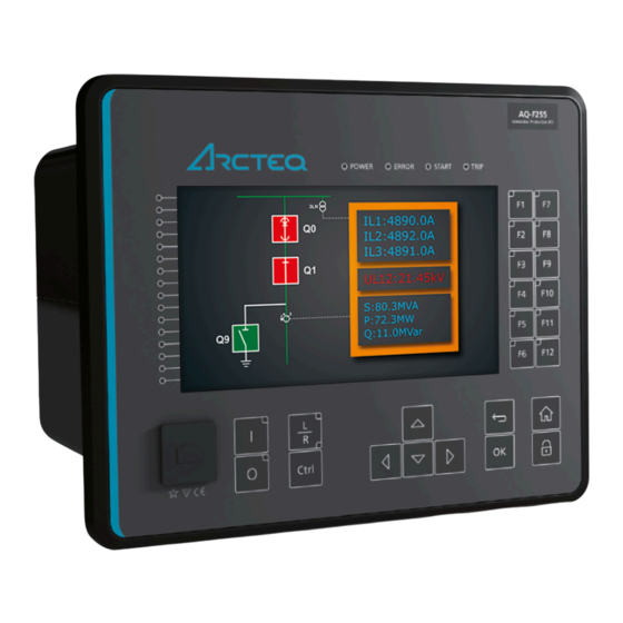
Version: 2.10 2 General The AQ-V251 voltage protection device is a member of the AQ 250 product line. The hardware and software are modular: the hardware modules are assembled and configured according to the application's I/O requirements and the software determines the available functions. This manual describes the specific application of the AQ-V251 voltage protection device. -
Page 12: Device User Int Vice User Interface Erface
Home Home and the password activation buttons). 6. Twelve (12) freely configurable function buttons (F1…F12). Each button has a freely configurable LED (red, orange, green). 7. One (1) RJ-45 Ethernet port for device configuration. © Arcteq Relays Ltd IM00067... -
Page 13: Configuring User Levels And Their Passwords
The different user levels and their star indicators are as follows (also, see the image below for the HMI view): • Super user (***) • Configurator (**) • Operator (*) • User ( - ) © Arcteq Relays Ltd IM00067... - Page 14 Unlocking and locking a user level generates a time-stamped event to the event log in all AQ 250 series devices. NOTICE! TICE! Any user level with a password automatically locks itself after half an hour (30 minutes) of inactivity. © Arcteq Relays Ltd IM00067...
-
Page 15: Functions Unctions
Instruction manual Version: 2.10 4 Functions 4.1 Functions included in AQ-V251 The AQ-V251 voltage protection relay includes the following functions as well as the number of stages in those functions. Table. 4.1 - 2. Protection fucntions of AQ-V251. Name ANSI Description U>... -
Page 16: Measurements
Milliampere output control ΔV/Δa/Δf Synchrocheck function Synchronizer GSYN ΔV/Δa/Δf (onl only y in Function package B!) Table. 4.1 - 4. Monitoring functions of AQ-V251. Name ANSI Description Voltage transformer supervision Disturbance recorder THDV Voltage total harmonic distortion MREC... - Page 17 VT ratings. In the figure below, three line-to-neutral voltages are connected along with the zero sequence voltage; therefore, the 3LN+U4 mode must be selected and the U4 channel must be set as U0. Other possible connections are presented later in this chapter. © Arcteq Relays Ltd IM00067...
- Page 18 ( Protection → Voltage → [protection stage menu] → INFO ; see the image below). The number of available protection functions depends on the device type. Figure. 4.2.1 - 4. Selecting the measured magnitude. © Arcteq Relays Ltd IM00067...
- Page 19 • 2LL+U3+U4 (two line-to-line voltages and the U3 and the U4 channels can be used for synchrochecking, zero sequence voltage, or for both) The 3LN+U0 is the most common voltage measurement mode. See below for example connections of voltage line-to-line measurement (3LL on the left, 2LL on the right). © Arcteq Relays Ltd IM00067...
- Page 20 In the image below is an example of 2LL+U0+SS, that is, two line-to-line measurements with the zero sequence voltage and voltage from side 2 for Synchrocheck. Since U0 is available, line-to-neutral voltages can be calculated. Figure. 4.2.1 - 7. 2LL+U0+SS settings and connections. © Arcteq Relays Ltd IM00067...
- Page 21 The measured voltage amplitude does not match one of the measured phases./ Check the wiring connections between the injection device or the VTs and the device. The calculated U0 is measured even though it should not. © Arcteq Relays Ltd IM00067...
- Page 22 "U4 mode U0 or SS" has been set to 2: Open the "U0" mode. delta Voltage 0: Disabled Activates the voltage memory. The "Voltage memory" memory 1: Activated Disabled chapter describes the function in more detail. © Arcteq Relays Ltd IM00067...
- Page 23 VT scaling A feedback value; the scaling factor for the primary factor p.u. Pri voltage's per-unit value. VT scaling A feedback value; the scaling factor for the factor p.u. Sec secondary voltage's per-unit value. © Arcteq Relays Ltd IM00067...
- Page 24 The secondary RMS voltage measurement from each of the voltage Ux 0.00…500.00 0.01 voltage channels. ("Ux Volt sec") Secondary voltage Ux 0.00…500.00 0.01 The secondary TRMS voltage (inc. harmonics up to 31 TRMS measurement from each of the voltage channels. ("UxVolt TRMS sec") © Arcteq Relays Ltd IM00067...
- Page 25 ("Pos.seq.Volt.sec") Secondary negative 0.00…4 The secondary measurement from the calculated sequence voltage 0.01 800.00 negative sequence voltage. ("Neg.seq.Volt.sec") Secondary zero sequence 0.00…4 The secondary measurement from the calculated zero voltage 0.01 800.00 sequence voltage. ("Zero.seq.Volt.sec") © Arcteq Relays Ltd IM00067...
- Page 26 UL1 mag") System voltage magnitude 0.00…1 The primary RMS line-to-neutral UL2 voltage (measured or calculated). You 0.01 can also select the row where the unit for this is kV. ("System 000.00 volt UL2 mag") © Arcteq Relays Ltd IM00067...
- Page 27 UL23 0.00…360.00 0.01 The primary line-to-line angle UL23 (measured or calculated). ("System volt UL23 ang") System voltage angle UL31 0.00…360.00 0.01 The primary line-to-line angle UL23 (measured or calculated). ("System volt UL31 ang") © Arcteq Relays Ltd IM00067...
- Page 28 Defines how the harmonics are displayed: in p.u. values, as 1: Primary V display primary voltage values, or as secondary voltage values. 2: Secondary V Maximum 0.00…100 Displays the maximum harmonics value of the selected harmonics value 0.01 000.00 voltage input Ux. ("UxMaxH") © Arcteq Relays Ltd IM00067...
-
Page 29: Voltage Memory
2. At least one phase current must be above the set value for the "Measured current condition 3I>" parameter. This setting limit is optional. Figure. 4.2.2 - 10. Distance protection characteristics and directional overcurrent. © Arcteq Relays Ltd IM00067... - Page 30 Table. 4.2.2 - 17. Measurement inputs of the voltage memory function. Signal Description Time base IL1RMS RMS measurement of phase L1 (A) current IL2RMS RMS measurement of phase L2 (B) current IL3RMS RMS measurement of phase L3 (C) current RMS measurement of voltage U © Arcteq Relays Ltd IM00067...
- Page 31 When the "Forced CT f tracking" parameter is activated and voltages are gone, the frequency from the selected current-based reference channel 3 (the current from IL3) is used for current sampling. This eliminates any possible measurement errors in the fixed frequency mode. Figure. 4.2.2 - 12. Frequency reference channels. © Arcteq Relays Ltd IM00067...
-
Page 32: Frequency Tracking And Scaling
The benefit of frequency tracking is that the measurements are within a pre-defined accuracy range even when the fundamental frequency of the power system changes. Frequency independent current and voltage measurement accuracy is achieved with algorithms specified in patent US 10,809,287. © Arcteq Relays Ltd IM00067... - Page 33 FFT calculation always has a whole power cycle in the buffer. The measurement accuracy is further improved by Arcteq's patented calibration algorithms that calibrate the analog channels against eight (8) system frequency points for both magnitude and angle.
- Page 34 6: References 2 & 3 trackable 7: All references trackable 0: No track ch Frequency 1: Ref1 Indicates which reference is used at the moment measurement 2: Ref2 for frequency tracking. in use 3: Ref3 © Arcteq Relays Ltd IM00067...
- Page 35 5: Track Ref 2 6: Track Ref 3 7: Fast Ref 1 8: Fast Ref 2 9: Fast Ref 3 Displays frequency used by "system set" channel SS1.meas.frqs 0.000…75.000Hz 0.001Hz - 1 and 2. © Arcteq Relays Ltd IM00067...
-
Page 36: General Menu
From HMI/setting tool only: Can only be changed from the setting HMI/setting Prohibited mode tool or HMI tool only Allowed: Can be changed from the setting tool, HMI, and IEC 2: Allowed 61850 client. © Arcteq Relays Ltd IM00067... - Page 37 0: - HMI restart 0: - When activated, display restarts. 1: Restart 0: Light Display color theme 0: Light Defines the color theme used in the HMI. theme 1: Dark theme theme © Arcteq Relays Ltd IM00067...
-
Page 38: Protection Functions
4.4.1 General properties of a protection function The following flowchart describes the basic structure of any protection function. The basic structure is composed of analog measurement values being compared to the pick-up values and operating time characteristics. © Arcteq Relays Ltd IM00067... - Page 39 A A Q Q -V251 -V251 4 Functions Instruction manual Version: 2.10 The protection function is run in a completely digital environment with a protection CPU microprocessor which also processes the analog signals transformed into the digital form. © Arcteq Relays Ltd IM00067...
- Page 40 Figure. 4.4.1 - 14. Pick up and reset. The pick-up activation of the function is not directly equal to the START signal generation of the function. The START signal is allowed if a blocking condition is not active. © Arcteq Relays Ltd IM00067...
- Page 41 (independent time characteristics). • Inverse definite minimum time (IDMT): activates the trip signal after a time which is in relation to the set pick-up value X and the measured value X (dependent time characteristics). © Arcteq Relays Ltd IM00067...
- Page 42 Selects whether the delay curve series for an IDMT operation follows either IEC or IEEE/ANSI standard Delay curve 0: IEC defined characteristics. 0: IEC series 1: IEEE This setting is active and visible when the "Delay type" parameter is set to "IDMT". © Arcteq Relays Ltd IM00067...
- Page 43 "Param". Defines the Constant C for IEEE characteristics. This setting is active and visible when the "Delay type" 0.0000…250.0000 0.0001 0.0200 parameter is set to "IDMT" and the "Delay characteristic" parameter is set to "Param". © Arcteq Relays Ltd IM00067...
- Page 44 NOTE TE: : when "k" has been set lower than 0.3 calculated operation time can be lower with mechanical relays. than 0 seconds with some measurement values. In these cases operation time will be instant. © Arcteq Relays Ltd IM00067...
- Page 45 1: Yes even if the pick-up element is reset. release time The behavior of the stages with different release time configurations are presented in the figures below. © Arcteq Relays Ltd IM00067...
- Page 46 A A Q Q -V251 -V251 4 Functions Instruction manual Version: 2.10 Figure. 4.4.1 - 18. No delayed pick-up release. Figure. 4.4.1 - 19. Delayed pick-up release, delay counter is reset at signal drop-off. © Arcteq Relays Ltd IM00067...
- Page 47 Figure. 4.4.1 - 21. Delayed pick-up release, delay counter value is decreasing during the release time. The resetting characteristics can be set according to the application. The default setting is delayed 60 ms and the time calculation is held during the release time. © Arcteq Relays Ltd IM00067...
-
Page 48: Circuit Breaker Failure Protection (Cbfp; 50Bf/52Bf)
• block signal check • time delay characteristics • output processing. The inputs of the function are the following: • operating mode selections • setting parameters • digital input signals • measured and pre-processed current magnitudes. © Arcteq Relays Ltd IM00067... - Page 49 CBFP function to monitor the output relays selected here, the "Operation mode selection" parameter monitor must be set to a mode that includes digital outputs (e.g. "DO only", "Current and DO", "Current or signals or DO"). © Arcteq Relays Ltd IM00067...
- Page 50 Selects the residual current monitoring source, which can be 0: Not I0Input 1: I01 either from the two separate residual measurements (I01 and I02) or in use 2: I02 from the phase current's calculated residual current. 3: I0Calc © Arcteq Relays Ltd IM00067...
- Page 51 The relay's Info page displays useful, real-time information on the state of the protection function. It is accessed either through the relay's HMI display, or through the setting tool software when it is connected to the relay and its Live Edit mode is active. © Arcteq Relays Ltd IM00067...
- Page 52 TRetr setting parameter will 1: Yes not be available. Retrip Retrip start the timer. This setting defines how long the starting time 0.000…1800.000s 0.005s 0.100s condition has to last before a RETRIP signal is activated. delay © Arcteq Relays Ltd IM00067...
- Page 53 The following figures present some typical cases of the CBFP function. Trip, Retrip and CBFP in the device configuration Figure. 4.4.2 - 23. Wiring diagram when Trip, Retrip and CBFP are configured to the device. © Arcteq Relays Ltd IM00067...
- Page 54 CBFP signal to the incoming feeder breaker. If the primary protection function clears the fault, both counters (RETRIP and CBFP) are reset as soon as the measured current is below the threshold settings. © Arcteq Relays Ltd IM00067...
- Page 55 (RETRIP and CBFP) are reset as soon as the measured current is below the threshold settings or the tripping signal is reset. This configuration allows the CBFP to be controlled with current- based functions alone, and other function trips can be excluded from the CBFP functionality. © Arcteq Relays Ltd IM00067...
- Page 56 This configuration allows the CBFP to be controlled with current-based functions alone, with added security from current monitoring. Other function trips can also be included in the CBFP functionality. © Arcteq Relays Ltd IM00067...
- Page 57 Probably the most common application is when the device's trip output controls the circuit breaker trip coil, while one dedicated CBFP contact controls the CBFP function. Below are a few operational cases regarding the various applications and settings of the CBFP function. © Arcteq Relays Ltd IM00067...
- Page 58 CBFP signal is sent to the incoming feeder circuit breaker. If the primary protection function clears the fault, the counter for CBFP resets as soon as the measured current is below the threshold settings. © Arcteq Relays Ltd IM00067...
- Page 59 This configuration allows the CBFP to be controlled by current-based functions alone, and other function trips can be excluded from the CBFP functionality. © Arcteq Relays Ltd IM00067...
- Page 60 This configuration allows the CBFP to be controlled by current-based functions alone, with added security from current monitoring. Other function trips can also be included to the CBFP functionality. © Arcteq Relays Ltd IM00067...
- Page 61 A A Q Q -V251 -V251 4 Functions Instruction manual Version: 2.10 Device configuration as a dedicated CBFP unit Figure. 4.4.2 - 31. Wiring diagram when the device is configured as a dedicated CBFP unit. © Arcteq Relays Ltd IM00067...
- Page 62 ON, OFF, or both. The events triggered by the function are recorded with a time stamp and with process data values. Table. 4.4.2 - 33. Event messages. Event block name Event names CBF1 Start ON CBF1 Start OFF © Arcteq Relays Ltd IM00067...
-
Page 63: Overvoltage Protection (U>; 59)
The overvoltage function uses a total of eight (8) separate setting groups which can be selected from one common source. © Arcteq Relays Ltd IM00067... - Page 64 Figure. 4.4.3 - 33. Simplified function block diagram of the U> function. Measured input The function block uses analog voltage measurement values. The monitored magnitudes are equal to RMS values. A -20 ms averaged value of the selected magnitude is used for pre-fault data registering. © Arcteq Relays Ltd IM00067...
- Page 65 The selection of the AI channel in use is made with a setting parameter. In all possible input channel variations the pre-fault condition is presented with a 20 ms averaged history value from -20 ms from START or TRIP event. Figure. 4.4.3 - 34. Selectable measurement magnitudes with 3LN+U4 VT connection. © Arcteq Relays Ltd IM00067...
- Page 66 2LL+U3+U4 mode is in use. General settings The following general settings define the general behavior of the function. These settings are static i.e. it is not possible to change them by editing the setting group. © Arcteq Relays Ltd IM00067...
- Page 67 1: On Displays the mode of OV block. 2: Blocked U> LN 3: Test This parameter is visible only when Allow setting of behaviour 4: Test/Blocked individual LN mode is enabled in General menu. 5: Off © Arcteq Relays Ltd IM00067...
- Page 68 The operating timers’ behavior during a function can be set for TRIP signal and also for the release of the function in case the pick-up element is reset before the trip time has been reached. There are three basic operating modes available for the function: © Arcteq Relays Ltd IM00067...
- Page 69 Resetting time. The time allowed between pick-ups if the Release pick-up has not led to a trip operation. During this time the 0.000…150.000s 0.005s 0.06s time delay START signal is held on for the timers if the delayed pick-up release is active. © Arcteq Relays Ltd IM00067...
- Page 70 The events triggered by the function are recorded with a time stamp and with process data values. Table. 4.4.3 - 42. Event messages. Event block name Event names Start ON Start OFF Trip ON Trip OFF Block ON Block OFF Start ON Start OFF Trip ON Trip OFF Block ON © Arcteq Relays Ltd IM00067...
-
Page 71: Undervoltage Protection (U<; 27)
The undervoltage function uses a total of eight (8) separate setting groups which can be selected from one common source. © Arcteq Relays Ltd IM00067... - Page 72 Figure. 4.4.4 - 37. Simplified function block diagram of the U< function. Measured input The function block uses analog voltage measurement values. The monitored voltage magnitudes are equal to RMS values. A -20 ms averaged value of the selected magnitude is used for pre-fault data registering. © Arcteq Relays Ltd IM00067...
- Page 73 The selection of the AI channel in use is made with a setting parameter. In all possible input channel variations the pre-fault condition is presented with a 20 ms averaged history value from -20 ms from START or TRIP event. Figure. 4.4.4 - 38. Selectable measurement magnitudes with 3LN+U4 VT connection. © Arcteq Relays Ltd IM00067...
- Page 74 2LL+U3+U4 mode is in use. General settings The following general settings define the general behavior of the function. These settings are static i.e. it is not possible to change them by editing the setting group. © Arcteq Relays Ltd IM00067...
- Page 75 U< pick-up setting. Please see the image below for a visualization of this function. If the block level is set to zero (0), blocking is not in use. © Arcteq Relays Ltd IM00067...
- Page 76 -1800.000...1800.000s 0.005s time towards a trip, this displays how much time is left to trip before tripping occurs. A(B) The ratio between U or U voltage and the pick-up meas 0.00...1250.00U 0.01U at the value. moment © Arcteq Relays Ltd IM00067...
- Page 77 • Inverse definite minimum time (IDMT): gives the TRIP signal after a time which is in relation to the set pick-up voltage U and the measured voltage U (dependent time characteristics). The IDMT function follows this formula: Where: © Arcteq Relays Ltd IM00067...
- Page 78 2: Yes even when the pick-up element is reset. release time The user can reset characteristics through the application. The default setting is a 60 ms delay; the time calculation is held during the release time. © Arcteq Relays Ltd IM00067...
- Page 79 Undervoltage Block ON Undervoltage Block OFF Start ON Start OFF Trip ON Trip OFF Block ON Block OFF Undervoltage Block ON Undervoltage Block OFF Start ON Start OFF Trip ON Trip OFF Block ON Block OFF © Arcteq Relays Ltd IM00067...
-
Page 80: Neutral Overvoltage Protection (U0>; 59N)
100/√3 V = 57.74 V. Below is the formula for symmetric component calculation (and therefore to zero sequence voltage calculation). Below are some examples of zero sequence calculation. © Arcteq Relays Ltd IM00067... - Page 81 IEC and ANSI standard time delays as well as custom parameters. The operational logic consists of the following: • input magnitude selection • input magnitude processing • threshold comparator • block signal check • time delay characteristics © Arcteq Relays Ltd IM00067...
- Page 82 Table. 4.4.5 - 53. Measurement inputs of the U0> function. Signal Description Time base U0RMS RMS measurement of voltage U0/V RMS measurement of voltage U RMS measurement of voltage U RMS measurement of voltage U © Arcteq Relays Ltd IM00067...
- Page 83 Pick-up setting U0set> Pick-up setting The pick-up activation of the function is not directly equal to the START signal generation of the function. The START signal is allowed if the blocking condition is not active. © Arcteq Relays Ltd IM00067...
- Page 84 The variables the user can set are binary signals from the system. The blocking signal needs to reach the device minimum of 5 ms before the set operating delay has passed in order for the blocking to activate in time. © Arcteq Relays Ltd IM00067...
- Page 85 0.01s 0.05s setting k Time dial/multiplier setting for IDMT characteristics. The setting is active and visible when IDMT is the selected IDMT delay type. 0.01…25.00s 0.01s 1.00s Multiplier IDMT time multiplier in the U power. © Arcteq Relays Ltd IM00067...
- Page 86 The events triggered by the function are recorded with a time stamp and with process data values. Table. 4.4.5 - 58. Event messages. Event block name Event names NOV1 Start ON NOV1 Start OFF NOV1 Trip ON NOV1 Trip OFF NOV1 Block ON NOV1 Block OFF NOV2 Start ON © Arcteq Relays Ltd IM00067...
- Page 87 Fault Pre-fault Trip time Date and time Event Fault type Used SG voltage voltage voltage remaining Start/Trip Start/ Start Setting dd.mm.yyyy Event L1-G…L1-L2-L3 -20ms Trip -200ms group 1...8 hh:mm:ss.mss name ms...1800s voltage voltage voltage active © Arcteq Relays Ltd IM00067...
-
Page 88: Sequence Voltage Protection (U1/U2>/<; 47/27P/59Pn)
Below is the formula for symmetric component calculation (and therefore to positive sequence voltage calculation). In what follows are three examples of positive sequence calculation (positive sequence component vector). Figure. 4.4.6 - 46. Normal situation. Figure. 4.4.6 - 47. Earth fault in an isolated network. © Arcteq Relays Ltd IM00067... - Page 89 Below is the formula for symmetric component calculation (and therefore to negative sequence voltage calculation). In what follows are three examples of negative sequence calculation (negative sequence component vector). Figure. 4.4.6 - 49. Normal situation. Figure. 4.4.6 - 50. Earth fault in isolated network. © Arcteq Relays Ltd IM00067...
- Page 90 START and TRIP events simultaneously with an equivalent time stamp. The time stamp resolution is 1 ms. The function also a resettable cumulative counter for the START, TRIP and BLOCKED events. The following figure presents a simplified function block diagram of the sequence voltage function. © Arcteq Relays Ltd IM00067...
- Page 91 In RMS values the pre-fault condition is presented with 20 ms averaged history value from -20 ms of START or TRIP event. General settings The following general settings define the general behavior of the function. These settings are static i.e. it is not possible to change them by editing the setting group. © Arcteq Relays Ltd IM00067...
- Page 92 U< pick-up setting. Please see the image below for a visualization of this function. If the block level is set to zero (0), blocking is not in use. © Arcteq Relays Ltd IM00067...
- Page 93 If the blocking signal is not activated when the pick-up element activates, a START signal is generated and the function proceeds to the time characteristics calculation. © Arcteq Relays Ltd IM00067...
- Page 94 DT is the selected delay type. operating 0.000…1800.000s 0.005s 0.040s When set to 0.000 s, the stage operates as instant without time added delay. When the parameter is set to 0.005...1800 s, delay the stage operates as independent delayed. © Arcteq Relays Ltd IM00067...
- Page 95 The events triggered by the function are recorded with a time stamp and with process data values. Table. 4.4.6 - 66. Event messages. Event block name Event names VUB1 Start ON © Arcteq Relays Ltd IM00067...
- Page 96 Table. 4.4.6 - 67. Register content. Pre-trigger Fault Pre-fault Trip time Date and time Event Used SG voltage voltage voltage remaining Setting dd.mm.yyyy Event Start/Trip -20ms Start/Trip Start -200ms 0 ms...1800s group 1...8 hh:mm:ss.mss name voltage voltage voltage active © Arcteq Relays Ltd IM00067...
-
Page 97: Overfrequency And Underfrequency Protection (F>/<; 81O/81U)
START and TRIP events simultaneously with an equivalent time stamp. The time stamp resolution is 1 ms. The function also provides a resettable cumulative counter for the START, TRIP and BLOCKED events. The following figures present simplified function block diagrams of the frequency function. © Arcteq Relays Ltd IM00067... - Page 98 L-N voltages of the second voltage transformer General settings The following general settings define the general behavior of the function. These settings are static i.e. it is not possible to change them by editing the setting group. © Arcteq Relays Ltd IM00067...
- Page 99 They define the maximum or minimum allowed measured frequency before action from the function. The function constantly calculates the ratio between the pick-up setting and the measured frequency. The reset ratio of 20mHz is built into the function and is always relative to the pick-up value. © Arcteq Relays Ltd IM00067...
- Page 100 The relay's Info page displays useful, real-time information on the state of the protection function. It is accessed either through the relay's HMI display, or through the setting tool software when it is connected to the relay and its Live Edit mode is active. © Arcteq Relays Ltd IM00067...
- Page 101 ON, OFF, or both. The events triggered by the function are recorded with a time stamp and with process data values. Table. 4.4.7 - 72. Event messages. Event block name Event names FRQV1 f> Start ON © Arcteq Relays Ltd IM00067...
- Page 102 Trip OFF FRQV1 f<<< Start ON FRQV1 f<<< Start OFF FRQV1 f<<< Trip ON FRQV1 f<<< Trip OFF FRQV1 f<<<< Start ON FRQV1 f<<<< Start OFF FRQV1 f<<<< Trip ON FRQV1 f<<<< Trip OFF © Arcteq Relays Ltd IM00067...
-
Page 103: Rate-Of-Change Of Frequency (Df/Dt>/<; 81R)
(i.e. becomes an islanded network). A generator that is not disconnected from the network can cause safety hazards. A generator can also be automatically reconnected to the network, which can cause damage to the generator and the network. © Arcteq Relays Ltd IM00067... - Page 104 • block signal check • time delay characteristics • output processing. The inputs for the function are the following: • operating mode selections • setting parameters • digital inputs and logic signals • measured and pre-processed frequency magnitudes. © Arcteq Relays Ltd IM00067...
- Page 105 L-N voltages of the second voltage transformer 5 ms General settings The following general settings define the general behavior of the function. These settings are static i.e. it is not possible to change them by editing the setting group. © Arcteq Relays Ltd IM00067...
- Page 106 "Falling" or "Both". Overfrequency limit. Tripping is permitted if df/dt>/< (1…8) measured frequency is above this value. This 0.01Hz/ 10.00…70.00Hz/s 51Hz/s f> limit parameter is visible only when operation mode is set to "Rising" or "Both". © Arcteq Relays Ltd IM00067...
- Page 107 If the blocking signal is not activated when the pick-up element activates, a START signal is generated and the function proceeds to the time characteristics calculation. © Arcteq Relays Ltd IM00067...
- Page 108 DFT1 df/dt>/< (4) Start ON DFT1 df/dt>/< (4) Start OFF DFT1 df/dt>/< (4) Trip ON DFT1 df/dt>/< (4) Trip OFF DFT1 df/dt>/< (5) Start ON DFT1 df/dt>/< (5) Start OFF DFT1 df/dt>/< (5) Trip ON © Arcteq Relays Ltd IM00067...
- Page 109 (7) Block OFF DFT1 df/dt>/< (8) Block ON DFT1 df/dt>/< (8) Block OFF The function registers its operation into the last twelve (12) time-stamped registers. The table below presents the structure of the function's register content. © Arcteq Relays Ltd IM00067...
-
Page 110: Resistance Temperature Detectors (Rtd)
2: Blocked Set mode of RTD block. RTD LN 3: Test 0: On This parameter is visible only when Allow setting of individual LN mode is mode 4: Test/ enabled in General menu. Blocked 5: Off © Arcteq Relays Ltd IM00067... - Page 111 Enables/disables the selection of Alarm 0: Disable 1: Enable 1 for the measurement channel x. Selects whether the alarm activates 0: > S1...S16 Alarm1 >/< 0: > when measurement is above or 1: < below the pick-up setting value. © Arcteq Relays Ltd IM00067...
- Page 112 (12) time-stamped registers. Table. 4.4.9 - 82. Event messages. Event block name Event names RTD1 S1 Alarm1 ON RTD1 S1 Alarm1 OFF RTD1 S1 Alarm2 ON RTD1 S1 Alarm2 OFF RTD1 S2 Alarm1 ON © Arcteq Relays Ltd IM00067...
- Page 113 S7 Alarm2 OFF RTD1 S8 Alarm1 ON RTD1 S8 Alarm1 OFF RTD1 S8 Alarm2 ON RTD1 S8 Alarm2 OFF RTD1 S9 Alarm1 ON RTD1 S9 Alarm1 OFF RTD1 S9 Alarm2 ON RTD1 S9 Alarm2 OFF © Arcteq Relays Ltd IM00067...
- Page 114 S15 Alarm2 ON RTD1 S15 Alarm2 OFF RTD1 S16 Alarm1 ON RTD1 S16 Alarm1 OFF RTD1 S16 Alarm2 ON RTD1 S16 Alarm2 OFF RTD2 S1 Meas Ok RTD2 S1 Meas Invalid RTD2 S2 Meas Ok © Arcteq Relays Ltd IM00067...
- Page 115 S12 Meas Invalid RTD2 S13 Meas Ok RTD2 S13 Meas Invalid RTD2 S14 Meas Ok RTD2 S14 Meas Invalid RTD2 S15 Meas Ok RTD2 S15 Meas Invalid RTD2 S16 Meas Ok RTD2 S16 Meas Invalid © Arcteq Relays Ltd IM00067...
-
Page 116: Programmable Stage (Pgx>/<; 99)
2: Blocked Set mode of PGS block. 3: Test PSx >/< LN mode This parameter is visible only when Allow setting of individual 4: Test/ LN mode is enabled in General menu. Blocked 5: Off © Arcteq Relays Ltd IM00067... - Page 117 The smallest value of the chosen signals is used in the selected) Mag2, Mag3) comparison. 3: Mag1 OR Any of the signals fulfills the pick-up condition. Each signal Mag2 OR has their own pick-up setting. Mag3 © Arcteq Relays Ltd IM00067...
- Page 118 (in p.u.) ILx 15 ILx 15 harmonic value (in p.u.) ILx 17 ILx 17 harmonic value (in p.u.) ILx 19 ILx 19 harmonic value (in p.u.) ILx TRMS ILx TRMS value (in p.u.) © Arcteq Relays Ltd IM00067...
- Page 119 UL23 Primary voltage V UL31Mag UL31 Primary voltage V UL1Mag UL1 Primary voltage V UL2Mag UL2 Primary voltage V UL3Mag UL3 Primary voltage V UL12Ang UL12 angle (degrees) UL23Ang UL23 angle (degrees) UL31Ang UL31 angle (degrees) © Arcteq Relays Ltd IM00067...
- Page 120 Reactance X L12, L23, L31, L1, L2, L3 primary (Ω) ZLxPri Impedance Z L12, L23, L31, L1, L2, L3 primary (Ω) RLxSec Resistance R L12, L23, L31, L1, L2, L3 secondary (Ω) XLxSec Reactance X L12, L23, L31, L1, L2, L3 secondary (Ω) © Arcteq Relays Ltd IM00067...
- Page 121 Table. 4.4.10 - 91. Other conductances, susceptances and admittances Name Description G0Pri Conductance G0 primary (mS) B0Pri Susceptance B0 primary (mS) G0Sec Conductance G0 secondary (mS) B0Sec Susceptance B0 secondary (mS) Y0Pri Admittance Y0 primary (mS) Y0Sec Admittance Y0 secondary (mS) © Arcteq Relays Ltd IM00067...
- Page 122 The relay's Info page displays useful, real-time information on the state of the protection function. It is accessed either through the relay's HMI display, or through the setting tool software when it is connected to the relay and its Live Edit mode is active. © Arcteq Relays Ltd IM00067...
- Page 123 The user can set the reset hysteresis in the function (by default 3 %). It is always relative to the Pick-up setting Mag value. © Arcteq Relays Ltd IM00067...
- Page 124 If the measured signal changes more than the set 4: Delta set (%) +/- > relative pick-up value in 20 ms, the comparison condition is fulfilled. The condition is dependent on direction. © Arcteq Relays Ltd IM00067...
- Page 125 The events triggered by the function are recorded with a time stamp and with process data values. Table. 4.4.10 - 96. Event messages. Event block name Event names PGS1 PS1 >/< Start ON PGS1 PS1 >/< Start OFF PGS1 PS1 >/< Trip ON PGS1 PS1 >/< Trip OFF © Arcteq Relays Ltd IM00067...
- Page 126 PS5 >/< Trip ON PGS1 PS5 >/< Trip OFF PGS1 PS5 >/< Block ON PGS1 PS5 >/< Block OFF PGS1 reserved PGS1 reserved PGS1 PS6 >/< Start ON PGS1 PS6 >/< Start OFF PGS1 PS6 >/< Trip ON © Arcteq Relays Ltd IM00067...
- Page 127 The function registers its operation into the last twelve (12) time-stamped registers. The register of the function records the ON event process data for START, TRIP or BLOCKED. The table below presents the structure of the function's register content. © Arcteq Relays Ltd IM00067...
-
Page 128: Control Functions
Setting groups can be controlled either by pulses or by signal levels. The setting group controller block gives setting groups priority values for situations when more than one setting group is controlled at the same time: the request from a higher-priority setting group is taken into use. © Arcteq Relays Ltd IM00067... - Page 129 This setting has to be active before the setting group can be changed group change Disabled remotely or from a local HMI. This parameter overrides the local control of Enabled the setting groups and it remains on until the user disables it. © Arcteq Relays Ltd IM00067...
- Page 130 The selection of Setting group 7 ("SG7"). Has the second lowest priority input in setting group control. group Can be controlled with pulses or static signals. If static signal control is applied, only SG8 requests will not be processed. © Arcteq Relays Ltd IM00067...
- Page 131 The status of the Petersen coil controls whether Setting group 1 is active. If the coil is disconnected, Setting group 2 is active. This way, if the wire is broken for some reason, the setting group is always controlled to SG2. © Arcteq Relays Ltd IM00067...
- Page 132 A A Q Q -V251 -V251 4 Functions Instruction manual Version: 2.10 Figure. 4.5.1 - 61. Setting group control – two-wire connection from Petersen coil status. © Arcteq Relays Ltd IM00067...
- Page 133 The application-controlled setting group change can also be applied entirely from the relay's internal logics. For example, the setting group change can be based on the cold load pick-up function (see the image below). © Arcteq Relays Ltd IM00067...
- Page 134 The function does not have a register. Table. 4.5.1 - 100. Event messages. Event block name Event names SG2 Enabled SG2 Disabled SG3 Enabled SG3 Disabled SG4 Enabled SG4 Disabled © Arcteq Relays Ltd IM00067...
- Page 135 Remote Change SG Request ON Remote Change SG Request OFF Local Change SG Request ON Local Change SG Request OFF Force Change SG ON Force Change SG OFF SG Request Fail Not configured SG ON © Arcteq Relays Ltd IM00067...
-
Page 136: Object Control And Monitoring
Manual remote control can be done through one of the various communication protocols available (Modbus, IEC101/103/104 etc.). The function supports the modes "Direct control" and "Select before execute" while controlled remotely. Automatic controlling can be done with functions like auto-reclosing function (ANSI 79). © Arcteq Relays Ltd IM00067... - Page 137 The following parameters help the user to define the object. The operation of the function varies based on these settings and the selected object type. The selected object type determines how much control is needed and which setting parameters are required to meet those needs. © Arcteq Relays Ltd IM00067...
- Page 138 Displays the status of breaker. Intermediate is displayed when 1: Open Breaker neither of the status signals (open or close) are active. Bad status 2: Closed status is displayed when both status signals (open and close) are active. 3: Bad © Arcteq Relays Ltd IM00067...
- Page 139 Displays the number of failed "Close" requests. 0…2 –1 failed Clear 0: - Clears the request statistics, setting them back to zero (0). 0: - statistics 1: Clear Automatically returns to "-" after the clearing is finished. © Arcteq Relays Ltd IM00067...
- Page 140 Objectx Open command The physical "Open" command pulse to the device's output ("Objectx Open relay. Command") OUT1…OUTx Objectx Close command The physical "Close" command pulse to the device's output ("Objectx Close relay. Command") © Arcteq Relays Ltd IM00067...
- Page 141 The remote Open command from a physical digital Open control input input (e.g. RTU). Objectx Application The Close command from the application. Can be any Close logical signal. Objectx Application The Close command from the application. Can be any Open logical signal. © Arcteq Relays Ltd IM00067...
- Page 142 Figure. 4.5.2 - 65. Example of an interlock application. In order for the blocking signal to be received on time, it has to reach the function 5 ms before the control command. © Arcteq Relays Ltd IM00067...
- Page 143 RMS measurement of phase L2 (B) current IL3RMS RMS measurement of phase L3 (C) current Condition monitoring parameters can be found from Control → Objects → Object X → APP CONTR → Condition Monitoring . © Arcteq Relays Ltd IM00067...
- Page 144 Condition Alarm 2 Enable Enables Alarm 2. 1: Enabled Disabled Condition Alarm 2 when When the amount of operations left is less than value 0...200 000 operations less than set here, Alarm 2 will activate. © Arcteq Relays Ltd IM00067...
- Page 145 Close Command On OBJ1...OBJ10 Close Command Off OBJ1...OBJ10 Open Blocked On OBJ1...OBJ10 Open Blocked Off OBJ1...OBJ10 Close Blocked On OBJ1...OBJ10 Close Blocked Off OBJ1...OBJ10 Object Ready OBJ1...OBJ10 Object Not Ready OBJ1...OBJ10 Sync Ok OBJ1...OBJ10 Sync Not Ok © Arcteq Relays Ltd IM00067...
- Page 146 The cause of an "Open" command's failure. Close fail The cause of a "Close" command's failure. Open command The source of an "Open" command. Close command The source of an "Open" command. General status The general status of the function. © Arcteq Relays Ltd IM00067...
-
Page 147: Indicator Object Monitoring
Close input A link to a physical digital input. The monitored indicator's signal selected by the user ("Ind.X CLOSE status. "1" refers to the active "Close" state of the monitored Close indicator. (SWx) Status In") © Arcteq Relays Ltd IM00067... -
Page 148: Synchrocheck (Δv/Δa/Δf; 25)
(UL12, UL23 or UL31). • SYN3 – Supervises the synchronization condition between the channels U3 and U4. The seven images below present three different example connections and four example applications of the synchrocheck function. © Arcteq Relays Ltd IM00067... - Page 149 Figure. 4.5.4 - 67. Example connection of the synchrocheck function (3LN+U4 mode, SYN1 in use, UL1 as reference voltage). Figure. 4.5.4 - 68. Example connection of the synchrocheck function (2LL+U0+U4 mode, SYN1 in use, UL12 as reference voltage). © Arcteq Relays Ltd IM00067...
- Page 150 Figure. 4.5.4 - 69. Example connection of the synchrocheck function (2LL+U3+U4 mode, SYN3 in use, UL12 as reference voltage). Figure. 4.5.4 - 70. Example application (synchrocheck over one breaker, with 3LL and 3LN VT connections). © Arcteq Relays Ltd IM00067...
- Page 151 A A Q Q -V251 -V251 4 Functions Instruction manual Version: 2.10 Figure. 4.5.4 - 71. Example application (synchrocheck over one breaker, with 2LL VT connection). © Arcteq Relays Ltd IM00067...
- Page 152 A A Q Q -V251 -V251 4 Functions Instruction manual Version: 2.10 Figure. 4.5.4 - 72. Example application (synchrocheck over two breakers, with 2LL VT connection). © Arcteq Relays Ltd IM00067...
- Page 153 "live" or a "dead" state. The parameter SYNx U conditions is used to determine the conditions (in addition to the three aspects) which are required for the systems to be considered synchronized. The image below shows the different states the systems can be in. © Arcteq Relays Ltd IM00067...
- Page 154 Instruction manual Version: 2.10 Figure. 4.5.4 - 74. System states. The following figures present simplified function block diagrams of the synchrocheck function. Figure. 4.5.4 - 75. Simplified function block diagram of the SYN1 and SYN2 function. © Arcteq Relays Ltd IM00067...
- Page 155 The relay's Info page displays useful, real-time information on the state of the protection function. It is accessed either through the relay's HMI display, or through the setting tool software when it is connected to the relay and its Live Edit mode is active. © Arcteq Relays Ltd IM00067...
- Page 156 If the blocking signal is active when the SYN OK activates, a BLOCKED signal is generated and the function does not process the situation further. If the SYN OK function has been activated before the blocking signal, it resets. © Arcteq Relays Ltd IM00067...
- Page 157 - 3LN+U4(SS) SYN1 V 0: Not 3: UL31 - 2LL+U3(U0)+U4(SS) Reference in use 4: UL1 - 2LL+U3(SS)+U4(U0) 5: UL2 Reference options 0...3 available: 6: UL3 - 3LL+U4(SS) - 2LL+U3(Not in use)+U4(SS) - 2LL+U3(SS)+U4(Not in use) © Arcteq Relays Ltd IM00067...
- Page 158 4: LL & DL 0: LL conditions 5: LL & DD only L = Live 6: LL & LD & DL D = Dead 7: LL & LD & DD 8: LL & DL & DD 9: Bypass © Arcteq Relays Ltd IM00067...
- Page 159 SYN1 Volt diff out of setting SYN1 SYN1 Angle diff Ok SYN1 SYN1 Angle diff out of setting SYN1 SYN1 Frequency diff Ok SYN1 SYN1 Frequency diff out of setting SYN1 SYN2 Blocked ON SYN1 SYN2 Blocked OFF © Arcteq Relays Ltd IM00067...
- Page 160 SYN3 Angle diff out of setting SYN1 SYN3 Frequency diff Ok SYN1 SYN3 Frequency diff out of setting SYN1 SYN1 Switch ON SYN1 SYN1 Switch OFF SYN1 SYN2 Switch ON SYN1 SYN2 Switch OFF SYN1 SYN3 Switch ON © Arcteq Relays Ltd IM00067...
-
Page 161: Milliampere Output Control
• good for travelling long distances, as current does not degrade over long connections like voltage does • less sensitive to background electrical noise • detects a fault in the system incredibly easily since 4 mA is equal to 0 % output. © Arcteq Relays Ltd IM00067... - Page 162 The second input point in the mA output 0.001 …10 value 2 control curve. Scaled The mA output value when the measured value mA output 0.0000…24.0000mA 0.0001mA 0mA is equal to or greater than Input value 2. value 2 © Arcteq Relays Ltd IM00067...
-
Page 163: Synchronizer (Δv/Δa/Δf; 25)
The synchronizer function is used to automatically synchronize generators to power grids. Proper synchronizing is essential to avoid inrush currents, power system oscillations as well as thermal and mechanical stress on the generator when connecting a synchronous generator to a grid. © Arcteq Relays Ltd IM00067... - Page 164 "Close" command signal is sent to the generator's circuit breaker. Pre-closing time can be used to allow for delay time in a circuit breaker and any auxiliary relays. The pre-closing angle is adjusted automatically depending on the slip frequency. © Arcteq Relays Ltd IM00067...
- Page 165 Table. 4.5.6 - 124. General setting and status indication parameters. Name Range Step Default Description Voltage 0: System is reference If “System is reference” is selected, difference System 1: U3/U4 input is “Synchronizer voltage reference” calculation reference determines reference voltage. mode reference © Arcteq Relays Ltd IM00067...
- Page 166 0.001deg 0deg was closed. closing BRK Estimated BRK Closing 0.000...360.000s 0.005s Estimated time left to breaker closing. time Networks Estimated time how long it takes for the 0.000...360.000s 0.005s rotating time network to rotate fully. © Arcteq Relays Ltd IM00067...
- Page 167 If underfrequency exceeds value underfrequency 0.00...2.00Hz 0.01Hz determined here, synchronizing is not difference to allowed. allow synchronizing Maximum time If synchronizing takes longer than the 0.000...1800.000s 0.005s 300.000s value determined here, synchronizing synchronizing will be cancelled. © Arcteq Relays Ltd IM00067...
- Page 168 Freq. Min. Minimum time between each frequency Resting time 0.000...1800.000s 0.005s 2.500s adjustment pulse. between pulses Frequency Determines how many Hz per second adjustment 0.00...10.00Hz/s 0.01Hz/s 0.10Hz/s frequency increases with frequency slope when increasing command. increasing © Arcteq Relays Ltd IM00067...
- Page 169 0.00...50.00Hz 0.01Hz 1.00Hz value gives pulses more frequently. pulse is generated Setting depends on the used application and its properties. Frequency adjustment 0.00...5000.00 0.01 1000.00 Base value for frequency pulse length. pulse length constant © Arcteq Relays Ltd IM00067...
- Page 170 Synchronizing Running ON GSYN Synchronizing Running OFF GSYN Synchr. Increase Voltage ON GSYN Synchr. Increase Voltage OFF GSYN Synchr. Decrease Voltage ON GSYN Synchr. Decrease Voltage OFF GSYN Synchr. Increase Frequency ON GSYN Synchr. Increase Frequency OFF © Arcteq Relays Ltd IM00067...
-
Page 171: Vector Jump (Δφ; 78)
(8) separate setting groups which can be selected from one common source. The operational logic consists of the following: • input magnitude selection • input magnitude processing • threshold comparator • two block signal checks (undervoltage block or stage external signal) • time delay characteristics © Arcteq Relays Ltd IM00067... - Page 172 A -20 ms averaged value of the selected magnitude is used for pre-fault data registering. Table. 4.5.7 - 128. Measurement inputs of the vector jump function. Signal Description Time base Measured line-to-line voltage U Measured line-to-line voltage U Measured line-to-line voltage U © Arcteq Relays Ltd IM00067...
- Page 173 (Δα ) for each of the selected voltages. The function's stage trip signal lasts for 20 ms and automatically resets after that time has passed. The setting value is common for all measured amplitudes. © Arcteq Relays Ltd IM00067...
- Page 174 1: System any 5: System all Defines the monitored voltage channel(s) voltages P-P Voltage P-E voltages 6: System any P-E voltage 7: System L1 Voltage 8: System L2 Voltage 9: System L3 Voltage 10: U4 Voltage © Arcteq Relays Ltd IM00067...
- Page 175 Displays the angle difference between present time and 20 ms -360...360deg 0.01deg difference ago. Δα > U3 Angle difference Δα > U1meas/ Δα > U2meas/ Displays the ratio between the measured voltage and -360...360p.u. 0.01p.u. undervoltage block limit setting. Δα > U3meas/ © Arcteq Relays Ltd IM00067...
- Page 176 Trip Δα meas / Alarm Δα meas / Date and time Event Fault type Used SG dataset dataset dd.mm.yyyy Event L1(2), L2(3), L3(1) Trip angle Alarm angle Setting group hh:mm:ss.mss name and U4 difference difference 1...8 active © Arcteq Relays Ltd IM00067...
-
Page 177: Programmable Control Switch
ON, OFF, or both. The function offers five (5) independent switches. Table. 4.5.8 - 135. Event messages. Event block name Event names Switch 1 ON Switch 1 OFF Switch 2 ON Switch 2 OFF Switch 3 ON Switch 3 OFF Switch 4 ON © Arcteq Relays Ltd IM00067... -
Page 178: User Buttons
Range Step Default Description Analog input 0: Disabled Enables and disables the input. scaling 1: Activated Disabled Scaling curve 0: Disabled Enables and disables the scaling curve and 1...4 1: Activated Disabled the input measurement. © Arcteq Relays Ltd IM00067... - Page 179 The signal can be assigned directly to an output relay or to an LED in the I/O matrix. The "Out of range" signal is activated, when the measured signal falls below the set input minimum limit, or when it exceeds the input maximum limit. © Arcteq Relays Ltd IM00067...
-
Page 180: Logical Outputs
64 logical outputs are available. The figure below presents a logic output example where a signal from the circuit breaker failure protection function controls the digital output relay number 5 ("OUT5") when the circuit breaker's cart status is "In". © Arcteq Relays Ltd IM00067... -
Page 181: Logical Inputs
AQ-200 unit or to give direct control commands. Logical inputs can be controlled with a virtual switch built in the mimic and from a SCADA system. Logical inputs are volatile signals: their status will always return to "0" when the AQ-200 device is rebooted. 32 logical inputs are available. © Arcteq Relays Ltd IM00067... - Page 182 Logical input descriptions Logical inputs can be given a description. The user defined description are displayed in most of the menus: • logic editor • matrix • block settings • event history • disturbance recordings • etc. © Arcteq Relays Ltd IM00067...
-
Page 183: Monitoring Functions
ON/OFF events to the common event buffer from each of the output signals. The time stamp resolution is 1 ms. The function also provides a resettable cumulative counter for the START, ALARM BUS, ALARM LINE and BLOCKED events. © Arcteq Relays Ltd IM00067... - Page 184 Figure. 4.6.1 - 86. Simplified function block diagram of the VTS function. Measured input The function block uses analog voltage measurement values. Function uses the RMS value of the voltage measurement inputs and the calculated (positive, negative and zero) sequence voltages. © Arcteq Relays Ltd IM00067...
- Page 185 Set mode of VTS block. Blocked VTS LN 3: Test 1: On This parameter is visible only when Allow setting of individual LN mode is mode 4: Test/ enabled in General menu. Blocked 5: Off © Arcteq Relays Ltd IM00067...
- Page 186 The voltage transformer supervision can also report several different states of the measured voltage. These can be seen in the function's INFO menu. Name Description Bus dead No voltages. Bus Live VTS Ok All of the voltages are within the set limits. © Arcteq Relays Ltd IM00067...
- Page 187 If the blocking signal is not activated when the pick-up element activates, a START signal is generated and the function proceeds to the time characteristics calculation. © Arcteq Relays Ltd IM00067...
- Page 188 The function registers its operation into the last twelve (12) time-stamped registers. The register of the function records the ON event process data for ACTIVATED, BLOCKED, etc. The table below presents the structure of the function's register content. © Arcteq Relays Ltd IM00067...
-
Page 189: Voltage Total Harmonic Distortion (Thd)
The outputs of the function are the START and ALARM ACT signals for the phase voltages ("THDV") as well as BLOCKED signals. The function uses a total of eight (8) separate setting groups which can be selected from one common source. The operational logic consists of the following: • input magnitude processing © Arcteq Relays Ltd IM00067... - Page 190 The selection of the calculation method is made with a setting parameter (common for all measurement channels). General settings The following general settings define the general behavior of the function. These settings are static i.e. it is not possible to change them by editing the setting group. © Arcteq Relays Ltd IM00067...
- Page 191 2: Blocked Displays the mode of THDV block. THDV> LN 3: Test This parameter is visible only when Allow setting of individual LN mode is behaviour 4: Test/ enabled in General menu. Blocked 5: Off © Arcteq Relays Ltd IM00067...
- Page 192 The events triggered by the function are recorded with a time stamp and with process data values. Table. 4.6.2 - 151. Event messages. Event block name Event names THDV1 Voltage THD Start ON THDV1 Voltage THD Start OFF THDV1 Voltage THD Alarm ON © Arcteq Relays Ltd IM00067...
-
Page 193: Disturbance Recorder (Dr)
Phase current I Phase current I Phase current I Residual current I coarse* I01c Residual current I fine* I01f I02c Residual current I coarse* Residual current I fine* I02f IL1” Phase current I (CT card 2) © Arcteq Relays Ltd IM00067... - Page 194 (VT card 2) UL2(3)VT2 Line-to-neutral U or line-to-line voltage U (VT card 2) UL3(1)VT2 U0(SS)VT2 Zero sequence voltage U or synchrocheck voltage U (VT card 2) USup_2 Voltage measurement module voltage supply supervision (VT card 2) © Arcteq Relays Ltd IM00067...
- Page 195 Res.I0x ampl. THD I02) Calculated I0 phase calc.I0 Pha.angle Res.I0x pow. THD Residual I0x power THD (I01, I02) angle Phase current TRMS Phase-to-phase current ILx (IL1, Pha.curr.ILx TRMS P-P curr.ILx ILx (IL1, IL2, IL3) IL2, IL3) © Arcteq Relays Ltd IM00067...
- Page 196 Primary positive sequence reactive per-unit values (IL1, Current p.u. Pri. current IL2, IL3) Positive sequence Pos.Seq. Resistive I0x Residual Resistive Primary residual resistive current resistive current in per- Current p.u. Current Pri. I0x (I01, I02) unit values © Arcteq Relays Ltd IM00067...
- Page 197 "50 Hz". Neutral Frequency at the moment. If the Primary neutral f atm. Display (when not conductance G frequency is not measurable, this conductance measurable is 0 Hz) (Pri) will show "0 Hz". © Arcteq Relays Ltd IM00067...
- Page 198 Ph.Rotating Logic Phase rotating order at the moment. MBIO ModB Channel 1...8 of MBIO Mod control 0=A-B-C, 1=A- If true ("1") the phase order is Ch x Invalid C is invalid reversed. © Arcteq Relays Ltd IM00067...
- Page 199 0.000...1800.000s 0.001s - Displays the maximum length of a single recording. recording Max. location of Displays the highest pre-triggering time that can be set 0.000...1800.000s 0.001s - the pre- with the settings currently in use. trigger © Arcteq Relays Ltd IM00067...
- Page 200 Disturbance recorder → Get DR files command. 0…95 freely Selects the digital channel for recording. Please see Recorder digital selectable the list of all available digital channels in the section channels channels titled "Analog and digital recording channels". © Arcteq Relays Ltd IM00067...
- Page 201 The recorder is configured by using the setting tool software or relay HMI, and the results are analyzed with the AQviewer software (is automatically downloaded and installed with AQtivate). Registered users can download the latest tools from the Arcteq website (arcteq.fi./downloads/).
- Page 202 ) . Alternatively, the user can load the recordings individually ( Disturbance recorder → DR List ) from a folder in the PC's hard disk drive; the exact location of the folder is described in Tools → Settings → DR path . © Arcteq Relays Ltd IM00067...
-
Page 203: Event Logger
Version: 2.10 The user can also launch the AQviewer software from the Disturbance recorder menu. AQviewer software instructions can be found in AQtivate 200 Instruction manual (arcteq.fi./downloads/). Events The disturbance recorder function (abbreviated "DR" in event block names) generates events and registers from the status changes of the function: the recorder generates an event each time it is triggered (manually or by dedicated signals). -
Page 204: Measurement Recorder
The setting tool estimates the maximum recording time, which depends on the recording interval. When the measurement recorder is running, the measurements can be viewed in graph form with the AQtivate PRO software (see the image below). © Arcteq Relays Ltd IM00067... - Page 205 V V olta oltage mea ge measur surements ements L2 Imp.React.Cap.E.Mvarh Res.Curr.I01 TRMS Pri U1Volt Pri L2 Imp.React.Cap.E.kvarh Res.Curr.I02 TRMS Pri U2Volt Pri L2 Exp/Imp React.Cap.E.bal.Mvarh Sec.Pha.Curr.IL1 U3Volt Pri L2 Exp/Imp React.Cap.E.bal.kvarh Sec.Pha.Curr.IL2 U4Volt Pri L2 Exp.React.Ind.E.Mvarh © Arcteq Relays Ltd IM00067...
- Page 206 Neg.Seq.Volt. p.u. Exp/Imp Act. E balance MWh Pha.L3 ampl. THD Zero.Seq.Volt. p.u. Exp/Imp Act. E balance kWh Pha.L1 pow. THD U1Volt Angle Exp.React.Cap.E.Mvarh Pha.L2 pow. THD U2Volt Angle Exp.React.Cap.E.kvarh Pha.L3 pow. THD U3Volt Angle Imp.React.Cap.E.Mvarh © Arcteq Relays Ltd IM00067...
- Page 207 S2 Measurement I” Pri.Neg.Seq.Curr. System Volt UL31 ang S3 Measurement I” Pri.Zero.Seq.Curr. System Volt UL1 ang S4 Measurement Res.Curr.I”01 TRMS Pri System Volt UL2 ang S5 Measurement Res.Curr.I”02 TRMS Pri System Volt UL3 ang S6 Measurement © Arcteq Relays Ltd IM00067...
- Page 208 L1 Exp.Active Energy kWh Curve1 Input Pha.IL”2 ampl. THD L1 Imp.Active Energy MWh Curve1 Output Pha.IL”3 ampl. THD L1 Imp.Active Energy kWh Curve2 Input Pha.IL”1 pow. THD L1 Exp/Imp Act. E balance MWh Curve2 Output © Arcteq Relays Ltd IM00067...
-
Page 209: Measurement Value Recorder
The user can set up to eight (8) magnitudes to be recorded when the function is triggered. An overcurrent fault type, a voltage fault type, and a tripped stage can be recorded and reported straight to SCADA. © Arcteq Relays Ltd IM00067... - Page 210 The tan (φ) of three-phase powers and phase powers. tanfiL3 cosfi3PH, cosfiL1, cosfiL2, The cos (φ) of three-phase powers and phase powers. cosfiL3 Impedances and admit Impedances and admittances tances Descrip Description tion © Arcteq Relays Ltd IM00067...
- Page 211 Reported values When triggered, the function holds the recorded values of up to eight channels, as set. In addition to this tripped stage, the overcurrent fault type and the voltage fault types are reported to SCADA. © Arcteq Relays Ltd IM00067...
- Page 212 45: U0> Trip 46: U0>> Trip 47: U0>>> Trip 48: U0>>>> Trip 0: - 1: A-G 2: B-G Overcurrent fault 3: A-B The overcurrent fault type. type 4: C-G 5: A-C 6: B-C 7: A-B-C © Arcteq Relays Ltd IM00067...
- Page 213 The user can select which event messages are stored in the main event buffer: ON, OFF, or both. Table. 4.6.6 - 163. Event messages. Event block name Event name VREC1 Recorder triggered ON VREC1 Recorder triggered OFF © Arcteq Relays Ltd IM00067...
-
Page 214: Communica A Tion
Ethernet and the Virtual Ethernet. Table. 5.1 - 165. Virtual Ethernet settings. Name Description Enable virtual adapter (No / Yes) Enable virtual adapter. Off by default. IP address Set IP address of the virtual adapter. © Arcteq Relays Ltd IM00067... - Page 215 Paritybits used by serial fiber channels. 2: Odd Stopbits 1...2 Stopbits used by serial fiber channels. 0: None 1: ModbutRTU 2: ModbusIO Protocol 3: IEC103 Communication protocol used by serial fiber channels. 4: SPA 5: DNP3 6: IEC101 © Arcteq Relays Ltd IM00067...
-
Page 216: Time Synchronization
Commands → Sync Time command or in the clock view from the HMI. When using Sync time command AQtivate sets the time to device the connected computer is currently using. Please note that the clock doesn't run when the device is powered off. © Arcteq Relays Ltd IM00067... -
Page 217: Ntp
Grandmaster available. In these situations the devices make a selection which device will act as the clock source. In these cases without GPS synchronized clock source, the accuracy between the devices is still high. © Arcteq Relays Ltd IM00067... -
Page 218: Communication Protocols
Communication → Protocols → IEC61850 . AQ-21x frame units support Edition 1 of IEC 61850. AQ-25x frame units support both Edition 1 and 2 of IEC 61850. The following services are supported by IEC 61850 in Arcteq devices: © Arcteq Relays Ltd... - Page 219 Communication → IEC 61850 → GOOSE subscriptions . Determines the general data reporting deadband General deadband 0.1…10.0 % settings. 0.1…1000.0 Determines the data reporting deadband settings Active energy deadband 2 kWh for this measurement. © Arcteq Relays Ltd IM00067...
-
Page 220: Logical Device Mode And Logical Node Mode
• LNBeh can be reported through Beh data object in all logical nodes. • LDMod is only visible through logical node zero's Mod data object (LLN0.Mod). Mode and behavior values There are 5 values defined for mode and behavior: On, Blocked, Test, Test / Blocked and Off. © Arcteq Relays Ltd IM00067... - Page 221 Table. 5.3.1.1 - 176. All possible logical device and logical node combinations. LDMod LNMod LNBeh Test / Blocked Test Blocked Test / Blocked Test / Blocked Test / Blocked Test Test / Blocked Blocked Test / Blocked Test / Blocked © Arcteq Relays Ltd IM00067...
- Page 222 Processed as Processed as Processed as Processed as Questionable questionable questionable questionable questionable processed q.test = False q.validity = Good Processed as Processed as Processed as Processed as invalid invalid valid valid processed q.test = True © Arcteq Relays Ltd IM00067...
- Page 223 “Processed as questionable” and “Processed as invalid” in the same way with “Not processed”. Only "Processed as valid" is passed to the application. Table. 5.3.1.1 - 178. Arcteq's implementation of processing of incoming data in different behaviors. Blocked...
-
Page 224: Goose
5: Off 5.3.1.2 GOOSE Arcteq relays support both GOOSE publisher and GOOSE subscriber. GOOSE subscriber is enabled with the "GOOSE subscriber enable" parameter at Communication → Protocols → IEC 61850/ GOOSE. The GOOSE inputs are configured using either the local HMI or the AQtivate software. - Page 225 For other publishers, non-simulated frames are accepted normally (given no simulated frame is received from that publisher). This behavior ends when the setting is set back to No. GOOSE input settings The table below presents the different settings available for all 64 GOOSE inputs. © Arcteq Relays Ltd IM00067...
- Page 226 Table. 5.3.1.2 - 185. GOOSE input user description. Name Range Default Description User editable 1...31 GOOSE Description of the GOOSE input. This description is used in several description GI x characters IN x menu types for easier identification. © Arcteq Relays Ltd IM00067...
- Page 227 GOOSE signals generate events from status changes. The user can select which event messages are stored in the main event buffer: ON, OFF, or both. The events triggered by the function are recorded with a time stamp and with process data values. The time stamp resolution is 1 ms. © Arcteq Relays Ltd IM00067...
-
Page 228: Modbus/Tcp And Modbus/Rtu
1. Some masters might begin numbering holding register from 0 instead of 1; this will cause an offset of 1 between the relay and the master. Modbus map can be edited with Modbus Configurator ( Tools → Communication → Modbus Configurator ). © Arcteq Relays Ltd IM00067... -
Page 229: Iec 103
TE: Once the configuration file has been loaded, the IEC 103 map of the relay can be found in the AQtivate software ( Tools → IEC 103 map ). The following table presents the setting parameters for the IEC 103 protocol. © Arcteq Relays Ltd IM00067... -
Page 230: Iec 101/104
Table. 5.3.4 - 191. IEC 104 settings. Name Range Step Default Description IEC 104 Disabled Enables and disables the IEC 104 communication protocol. enable Disabled Enabled 0…65 IP port 2404 Defines the IP port used by the protocol. © Arcteq Relays Ltd IM00067... - Page 231 4: 1/10 000 Power factor 5: 1/100 000 6: 1/1 000 000 Frequency 7: 10 8: 100 9: 1000 Current 10: 10 000 11: 100 000 Residual current 12: 1 000 000 Voltage Residual voltage Angle © Arcteq Relays Ltd IM00067...
-
Page 232: Spa
The full SPA signal map can be found in AQtivate ( Tools → SPA map ). The SPA event addresses can be found at Tools → Events and logs → Event list . © Arcteq Relays Ltd IM00067... -
Page 233: Dnp3
Defines the address for the allowed master. address Link layer 0…60 Defines the length of the time-out for the link layer. time-out 000ms Link layer 1…20 Defines the number of retries for the link layer. retries © Arcteq Relays Ltd IM00067... - Page 234 4: Var 5 0: Var 1 1: Var 2 2: Var 3 Group 32 variation (AI change) 4: Var 5 Selects the variation of the analog signal change. 3: Var 4 4: Var 5 5: Var 7 © Arcteq Relays Ltd IM00067...
-
Page 235: Modbus I/O
Range Description I/O module Defines the Modbus unit address for the selected I/O Module (A, B, or C). If 0…247 X address this setting is set to "0", the selected module is not in use. © Arcteq Relays Ltd IM00067... -
Page 236: Analog Fault Registers
TRIP signal, its START trigger signal signal, or either one. START and TRIP signals Recorded - 1000 000.00…1 000 Displays the recorded measurement value at the fault 0.01 - 000.00 time of the selected fault register trigger. value © Arcteq Relays Ltd IM00067... -
Page 237: Real-Time Measurements To Communication
UL12Ang, UL23Ang, UL31Ang, Angles of phase voltages, phase-to-phase voltages and residual voltages. U0Ang, U0CalcAng U1 Pos.seq V Ang, U2 Neg.seq V Positive and negative sequence angles. Powers S3PH P3PH Three-phase apparent, active and reactive power. Q3PH © Arcteq Relays Ltd IM00067... - Page 238 M thermal T Motor thermal temperature. F thermal T Feeder thermal temperature. T thermal T Transformer thermal temperature. RTD meas 1…16 RTD measurement channels 1…16. Ext RTD meas 1…8 External RTD measurement channels 1…8 (ADAM module). © Arcteq Relays Ltd IM00067...
-
Page 239: Modbus Gateway
-10 000 000.000…10 000 Magnitude X 0.001 - The unit depends on the selected 000.000 magnitude (either amperes, volts, or per- unit values). 5.6 Modbus Gateway Figure. 5.6 - 92. Example setup of Modbus Gateway application. © Arcteq Relays Ltd IM00067... - Page 240 Arc protection relays AQ-103 and AQ-103 LV Modbus variant is designed to work as a sub unit with Modbus Gateway master. More details about AQ-103 and AQ-103 LV capabilities and how to set them up can be found in AQ-103 Instruction manual (arcteq.fi./downloads/). Also see application example at the end of this chapter.
- Page 241 RTU. AQ-103 Modbus variant is able to report various signals like number of installed sensors, sensor activations, I/O activations etc. Holding registers of each signal can be found in the AQ-103 instruction manual. © Arcteq Relays Ltd IM00067...
- Page 242 Figure. 5.6 - 94. To report imported bit signals to SCADA the signals must be connected to a logical output. © Arcteq Relays Ltd IM00067...
- Page 243 A A Q Q -V251 -V251 5 Communication Instruction manual Version: 2.10 Figure. 5.6 - 95. Example mimic where sensor activation location is indicated with a symbol. © Arcteq Relays Ltd IM00067...
-
Page 244: Connections Of Aq-V251
A A Q Q -V251 -V251 6 Connections and application examples Instruction manual Version: 2.10 6 Connections and application examples 6.1 Connections of AQ-V251 Figure. 6.1 - 96. AQ-V251 variant without add-on modules. © Arcteq Relays Ltd IM00067... - Page 245 A A Q Q -V251 -V251 6 Connections and application examples Instruction manual Version: 2.10 Figure. 6.1 - 97. AQ-V251 variant with digital input and output modules. © Arcteq Relays Ltd IM00067...
-
Page 246: Application Example And Its Connections
6 Connections and application examples Instruction manual Version: 2.10 Figure. 6.1 - 98. AQ-V251 application example with function block diagram. 6.2 Application example and its connections This chapter presents an application example for the voltage protection relay. Since three line-to-neutral voltages and the zero sequence voltage (U4) are connected, this application uses the voltage measurement mode "3LN+U0"... -
Page 247: Trip Circuit Supervision (95)
(52b) even after the circuit breaker is opened. This requires a resistor which reduces the current: this way the coil is not energized and the relay output does not need to cut off the coil's inductive current. © Arcteq Relays Ltd IM00067... - Page 248 Non-latched outputs are seen as hollow circles in the output matrix, whereas latched contacts are painted. See the image below of an output matrix where a non-latched trip contact is used to open the circuit breaker. © Arcteq Relays Ltd IM00067...
- Page 249 (in an open state) cannot be monitored as the digital input is shorted by the device's trip output. Figure. 6.3 - 103. Trip circuit supervision with one DI and one latched output contact. © Arcteq Relays Ltd IM00067...
- Page 250 Logical output can be used in the output matrix or in SCADA as the user wants. The image below presents a block scheme when a non-latched trip output is not used. Figure. 6.3 - 104. Example block scheme. © Arcteq Relays Ltd IM00067...
-
Page 251: Construction And Installation Tion
The images below present the modules of both the non-optioned model (AQ- X251-XXXXXXX-AAAAAAAAAAAAA AAAAAAAAAAAAA, on the left) and the fully optioned model (AQ- X251-XXXXXXX-BBBBBBBBBBCC BBBBBBBBBBCCJ J , on the right). Figure. 7.1 - 105. Modular construction of AQ-X251-XXXXXXX-AAAAAAAAAAAAA © Arcteq Relays Ltd IM00067... - Page 252 In field upgrades, therefore, add-on modules must be ordered from Arcteq Relays Ltd. or its representative who can then provide the module with its corresponding unlocking code to allow the device to operate correctly once the hardware configuration has been upgraded.
- Page 253 (DO1…DO5) in the CPU module, and the rest in Slots L and M in groups of five. Additionally, there is a double (LC) fiber Ethernet communication option card installed in Slot N. These same principles apply to all non-standard configurations in the AQ-X251 devices. © Arcteq Relays Ltd IM00067...
-
Page 254: Cpu Module
Output relay 2, with a normally open (NO) contact. X1-9:10 Output relay 3, with a normally open (NO) contact. X1-11:12 Output relay 4, with a normally open (NO) contact. X1-13:14:15 Output relay 5, with a changeover contact. © Arcteq Relays Ltd IM00067... - Page 255 Digital input and output descriptions CPU card digital inputs and outputs can be given a description. The user defined description are displayed in most of the menus: • logic editor • matrix © Arcteq Relays Ltd IM00067...
-
Page 256: Voltage Measurement Module
0…15 milliseconds in theory and 2…13 milliseconds in practice. NOTICE! TICE! The mechanical delay of the relay is no not t included in these approximations! 7.3 Voltage measurement module Figure. 7.3 - 109. Voltage measurement module. © Arcteq Relays Ltd IM00067... -
Page 257: Option Cards
For further details please refer to the "Voltage measurement" chapter in the “Technical data” section of this document. 7.4 Option cards 7.4.1 Digital input module (optional) Figure. 7.4.1 - 110. Digital input module (DI8) with eight add-on digital inputs. © Arcteq Relays Ltd IM00067... - Page 258 When "NO" is the selected polarity, the measured voltage Activation 16.0…200.0 V 0.1 V 88 V exceeding this setting activates the input. When "NC" is the threshold selected polarity, the measured voltage exceeding this setting deactivates the input. © Arcteq Relays Ltd IM00067...
- Page 259 Figure. 7.4.1 - 111. Digital input state when energizing and de-energizing the digital input channels. Digital input descriptions Option card inputs can be given a description. The user defined description are displayed in most of the menus: • logic editor © Arcteq Relays Ltd IM00067...
-
Page 260: Digital Output Module (Optional)
Range Step Description DIx Voltage now 0.000...275.000 V 0.001 V Voltage measurement of a digital input channel. 7.4.2 Digital output module (optional) Figure. 7.4.2 - 112. Digital output module (DO5) with five add-on digital outputs. © Arcteq Relays Ltd IM00067... - Page 261 NOTICE! TICE! After editing user descriptions the event history will start to use the new description only after resetting the HMI. HMI can be reset from General → Device info → LCD restart . © Arcteq Relays Ltd IM00067...
-
Page 262: Rtd Input Module (Optional)
The RTD input module is an add-on module with eight (8) RTD input channels. Each input supports 2-wire, 3-wire and 4-wire RTD sensors. The sensor type can be selected with software for two groups, four channels each. The card supports Pt100 and Pt1000 sensors © Arcteq Relays Ltd IM00067... -
Page 263: Serial Rs-232 Communication Module (Optional)
Description • Serial-based communications • Wavelength 660 nm Serial fiber (GG/PP/ COM E • Compatible with 50/125 μm, 62.5/125 μm, 100/140 μm, and 200 μm GP/PG) Plastic-Clad Silica (PCS) fiber • Compatible with ST connectors © Arcteq Relays Ltd IM00067... - Page 264 COM F – Clock sync GND Clock synchronization input Pin 12 The option card includes two serial communication interfaces: COM E is a serial fiber interface with glass/plastic option, COM F is an RS-232 interface. © Arcteq Relays Ltd IM00067...
-
Page 265: Lc Or Rj45 100 Mbps Ethernet Communication Module (Optional)
• Communication port D, 100 Mbps LC fiber connector. • RJ-45 connectors COM D: • 62.5/125 μm or 50/125 μm multimode (glass). • 10BASE-T and 100BASE-TX • Wavelength 1300 nm. Both cards support both HSR and PRP protocols. © Arcteq Relays Ltd IM00067... -
Page 266: Double St 100 Mbps Ethernet Communication Module (Optional)
For other redundancy options, please refer to the option card "LC 100 Mbps Ethernet communication module". The images below present two example configurations: the first displays a ring configuration (note how the third party devices are connected in a separate ring), while the second displays a multidrop configuration. © Arcteq Relays Ltd IM00067... - Page 267 A A Q Q -V251 -V251 7 Construction and installation Instruction manual Version: 2.10 Figure. 7.4.6 - 118. Example of a ring configuration. Figure. 7.4.6 - 119. Example of a multidrop configuration. © Arcteq Relays Ltd IM00067...
-
Page 268: Double Rj45 10/100 Mbps Ethernet Communication Module (Optional)
• Two Ethernet ports RJ-45 connectors • RJ-45 connectors • 10BASE-T and 100BASE-TX This option card supports multidrop configurations. For other redundancy options, please refer to the option card "LC 100 Mbps Ethernet communication module". © Arcteq Relays Ltd IM00067... -
Page 269: Dimensions And Installation
(½) of the rack's width, meaning that a total of two devices can be installed to the same rack next to one another. The figures below describe the device dimensions (first figure), the device installation (second), and the panel cutout dimensions and device spacing (third). Figure. 7.5 - 122. Device dimensions. © Arcteq Relays Ltd IM00067... - Page 270 A A Q Q -V251 -V251 7 Construction and installation Instruction manual Version: 2.10 Figure. 7.5 - 123. Device installation. © Arcteq Relays Ltd IM00067...
- Page 271 A A Q Q -V251 -V251 7 Construction and installation Instruction manual Version: 2.10 Figure. 7.5 - 124. Panel cut-out and spacing of the devices. © Arcteq Relays Ltd IM00067...
-
Page 272: Technic Echnical Da Al Data Ta
630 V (continuous) Thermal withstand NOTICE! TICE! Voltage measurement accuracy has been verified with 50/60 Hz. The amplitude difference is 0.2 % and the angle difference is 0.5 degrees higher at 16.67 Hz and other frequencies. © Arcteq Relays Ltd IM00067... -
Page 273: Voltage Memory
(50Hz/20ms before “bolted” fault) 8.1.1.3 Frequency measurement Table. 8.1.1.3 - 215. Frequency measurement accuracy. Frequency measurement performance Frequency measuring range 6…75 Hz fundamental, up to the 31 harmonic current or voltage Inaccuracy 10 mHz © Arcteq Relays Ltd IM00067... -
Page 274: Cpu & Power Supply
< 40 W Maximum permitted interrupt time < 40 ms with 24 VDC DC ripple < 15 % Terminal block connection Terminal block Phoenix Contact MSTB 2,5/5-ST-5,08 Solid or stranded wire Maximum wire diameter 2.5 mm Other © Arcteq Relays Ltd IM00067... -
Page 275: Cpu Communication Ports
Data transfer rate 100 MB/s System integration Can be used for system protocols and for local programming Table. 8.1.2.2 - 221. Rear panel system communication port B. Port Port media Copper RS-485 Number of ports Features © Arcteq Relays Ltd IM00067... -
Page 276: Cpu Digital Inputs
Continuous carry Make and carry 0.5 s 30 A Make and carry 3 s 15 A Breaking capacity, DC (L/R = 40 ms) at 48 VDC at 110 VDC 0.4 A at 220 VDC 0.2 A © Arcteq Relays Ltd IM00067... -
Page 277: Option Cards
8.1.3 Option cards 8.1.3.1 Digital input module Table. 8.1.3.1 - 225. Technical data for the digital input module. General information Spare part code #SP-250-DI8 Compatibility AQ-250 series models Rated values Rated auxiliary voltage 5…265 V (AC/DC) © Arcteq Relays Ltd IM00067... -
Page 278: Digital Output Module
0.4 A at 220 VDC 0.2 A Control rate 5 ms Settings Polarity Software settable: Normally On/Normally Off Terminal block connection Terminal block Phoenix Contact MSTB 2,5/5-ST-5,08 Solid or stranded wire Maximum wire diameter 2.5 mm © Arcteq Relays Ltd IM00067... -
Page 279: Milliampere Module (Ma Out & Ma In)
8.1.3.4 RTD input module Table. 8.1.3.4 - 228. Technical data for the RTD input module. General information Spare part code #SP-2xx-RTD Compatibility AQ-200 series & AQ-250 series models Channels 1-8 2/3/4-wire RTD Pt100 or Pt1000 © Arcteq Relays Ltd IM00067... -
Page 280: Serial Fiber Communication Module
AQ-200 series & AQ-250 series models Protocols Protocols HSR and PRP Ports Quantity of fiber ports LC fiber connector Communication port C & D Wavelength 1300 nm Fiber cable 50/125 μm or 62.5/125 μm multimode (glass) © Arcteq Relays Ltd IM00067... -
Page 281: Double St 100 Mbps Ethernet Communication Module
General information Spare part code #SP-200-DISP Compatibility AQ-250 series models Dimensions and resolution Number of dots/resolution 800 x 480 Size 154.08 × 85.92 mm (6.06 × 3.38 in) Display Type of display Color RGB color © Arcteq Relays Ltd IM00067... -
Page 282: Functions
97 % of the pick-up current setting Reset time <50 ms 8.2.1.2 Overvoltage protection (U>; 59) Table. 8.2.1.2 - 234. Technical data for the overvoltage function. Measurement inputs Voltage inputs (+ U Voltage input magnitudes RMS line-to-line or line-to-neutral voltages Pick-up © Arcteq Relays Ltd IM00067... -
Page 283: Undervoltage Protection (U<; 27)
Table. 8.2.1.3 - 235. Technical data for the undervoltage function. Measurement inputs Voltage inputs (+ U Voltage input magnitudes RMS line-to-line or line-to-neutral voltages Pick-up 1 voltage Pick-up terms 2 voltages 3 voltages Pick-up setting 0.00…120.00 %U , setting step 0.01 %U © Arcteq Relays Ltd IM00067... -
Page 284: Neutral Overvoltage Protection (U0>; 59N)
8.2.1.4 Neutral overvoltage protection (U0>; 59N) Table. 8.2.1.4 - 236. Technical data for the neutral overvoltage function. Measurement inputs Residual voltage from U3 or U4 voltage channel Voltage input (selectable) Residual voltage calculated from U © Arcteq Relays Ltd IM00067... -
Page 285: Sequence Voltage Protection (U1/U2>/<; 47/27P/59Np)
Measurement inputs Voltage inputs (+ U Positive sequence voltage (I1) Voltage input calculations Negative sequence voltage (I2) Pick-up Pick-up setting 5.00…150.00 %U , setting step 0.01 %U Inaccuracy: ±1.5 %U or ±30 mV - Voltage © Arcteq Relays Ltd IM00067... -
Page 286: Overfrequency And Underfrequency Protection (F>/<; 81O/81U)
7.00…65.00 Hz, setting step 0.01 Hz Inaccuracy (sampling mode): ±20 mHz (50/60 Hz fixed frequency) - Fixed ±20 mHz (U > 30 V secondary) - Tracking ±20 mHz (I > 30 % of rated secondary) © Arcteq Relays Ltd IM00067... -
Page 287: Rate-Of-Change Of Frequency Protection (Df/Dt>/<; 81R)
10.00…70.00 Hz, setting step 0.01 Hz f< limit 7.00…65.00 Hz, setting step 0.01 Hz Pick-up inaccuracy Df/dt ±5.0 %I or ±20 mHz/s ±15 mHz (U > 30 V secondary) Frequency ±20 mHz (I > 30 % of rated secondary) © Arcteq Relays Ltd IM00067... -
Page 288: Resistance Temperature Detectors (Rtd)
8.2.2.1 Setting group selection Table. 8.2.2.1 - 241. Technical data for the setting group selection function. Settings and control modes Setting groups 8 independent, control-prioritized setting groups Control scale Common for all installed functions which support setting groups © Arcteq Relays Ltd IM00067... -
Page 289: Object Control And Monitoring
External object control time <75 ms Object control during auto-reclosing See the technical sheet for the auto-reclosing function. 8.2.2.3 Indicator object monitoring Table. 8.2.2.3 - 243. Technical data for the indicator object monitoring function. General Number of objects © Arcteq Relays Ltd IM00067... -
Page 290: Vector Jump (Δφ; 78)
Table. 8.2.2.5 - 245. Technical data for the synchrocheck function. Input signals Voltage inputs U1, U2, U3 or U4 voltage channel RMS line-to-line or line-to-neutral voltages Voltage input magnitudes U3 or U4 voltage channel RMS Pick-up © Arcteq Relays Ltd IM00067... -
Page 291: Monitoring Functions
L-L voltage. 8.2.3 Monitoring functions 8.2.3.1 Voltage transformer supervision (60) Table. 8.2.3.1 - 246. Technical data for the voltage transformer supervision function. Measurement inputs Voltage inputs Voltage input magnitudes RMS line-to-line or line-to-neutral voltages Pick-up © Arcteq Relays Ltd IM00067... -
Page 292: Disturbance Recorder
Freely selectable analog and binary signals channels 5 ms sample rate (FFT) Performance Sample rate 8, 16, 32 or 64 samples/cycle 0.000…1800.000 s, setting step 0.001 s Recording length The maximum length is determined by the chosen signals. © Arcteq Relays Ltd IM00067... -
Page 293: Event Logger
= 150 kHz…80 MHz, 10 V (RMS) EN 60255-26, IEC 61000-4-6 Table. 8.3 - 250. Voltage tests. Dielectric voltage test EN 60255-27, IEC 60255-5, EN 60255-1 2 kV, 50 Hz, 1 min Impulse voltage test © Arcteq Relays Ltd IM00067... - Page 294 Table. 8.3 - 253. Environmental conditions. IP classes IP54 (front) Casing protection class IP21 (rear) Temperature ranges Ambient service temperature range –35…+70 °C Transport and storage temperature range –40…+70 °C Other Altitude <2000 m Overvoltage category Pollution degree © Arcteq Relays Ltd IM00067...
- Page 295 Height: 208 mm Dimensions Width: 257 mm (½ rack) Depth: 165 mm (no cards or connectors) Weight 1.5 kg With packaging (gross) Height: 250 mm Dimensions Width: 343 mm Depth: 256 mm Weight 2.0 kg © Arcteq Relays Ltd IM00067...
-
Page 296: Ordering Inf Dering Informa Ormation Tion
External 8-ch Thermocouple mA Input module, pre- Requires an external 24 VDC AX008 configured supply. AX013 AQ-250 series raising frame 120mm AQX014 AQ-250 series raising frame 40mm AQX015 AQ-250 series wall mounting bracket © Arcteq Relays Ltd IM00067... - Page 297 Max. cable length 200 m AQ-02B Pressure and light point sensor unit (25,000 lux threshold) Max. cable length 200 m AQ-02C Pressure and light point sensor unit (50,000 lux threshold) Max. cable length 200 m © Arcteq Relays Ltd IM00067...
-
Page 298: Contact And R Ence Informa Ormation Tion
Arcteq Relays Ltd. Visiting and postal address Kvartsikatu 2 A 1 65300 Vaasa, Finland Contacts Phone: +358 10 3221 370 Website: arcteq.fi Technical support: support.arcteq.fi +358 10 3221 388 (EET 9:00 – 17.00) E-mail (sales): sales@arcteq.fi © Arcteq Relays Ltd IM00067...
Need help?
Do you have a question about the AQ-V251 and is the answer not in the manual?
Questions and answers