Table of Contents
Advertisement
Quick Links
For replacement parts visit
WENPRODUCTS.COM
Your new tool has been engineered and manufactured to WEN's highest standards for dependability, ease
of operation, and operator safety. When properly cared for, this product will supply you years of rugged,
trouble-free performance. Pay close attention to the rules for safe operation, warnings, and cautions.
If you use your tool properly and for its intended purpose, you will enjoy years of safe, reliable service.
NOTICE: Please refer to wenproducts.com for the most up-to-date instruction manual.
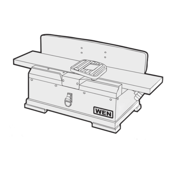
BENCHTOP JOINTER
IMPORTANT:
NEED HELP? CONTACT US!
Have product questions? Need technical support?
Please feel free to contact us at:
MODEL 6560, 6560T
6-INCH
4005911
Advertisement
Table of Contents

Related Manuals for Wen 6560T


Summary of Contents for Wen 6560T
- Page 1 4005911 IMPORTANT: Your new tool has been engineered and manufactured to WEN’s highest standards for dependability, ease of operation, and operator safety. When properly cared for, this product will supply you years of rugged, trouble-free performance. Pay close attention to the rules for safe operation, warnings, and cautions.
-
Page 2: Table Of Contents
Operation ..................13 Maintenance .................. 17 Troubleshooting Guide ..............19 Exploded View & Parts List ............20 Warranty Statement ............... 23 SPECIFICATIONS Model Number 6560, 6560T Motor 120V, 60 Hz, 10A Cutterhead Rotation Speed 10,000 RPM Cuts Per Minute 20,000 CPM Max Cutting Width 6-1/8 in. -
Page 3: Introduction
INTRODUCTION Thanks for purchasing the WEN Jointer. We know you are excited to put your tool to work, but first, please take a moment to read through the manual. Safe operation of this tool requires that you read and understand this operator’s manual and all the labels affixed to the tool. This manual provides information regarding potential safety concerns, as well as helpful assembly and operating instructions for your tool. -
Page 4: General Safety Rules
GENERAL SAFETY RULES Safety is a combination of common sense, staying alert and knowing how your item works. SAVE THESE SAFETY INSTRUCTIONS. WARNING: Read and understand all warnings, cautions and operating instructions before using this tool. Failure to follow all instructions listed below may result in personal injury and tool damage. - Page 5 GENERAL SAFETY RULES 4. Prevent unintentional starting. Ensure the switch is in the off-position before connecting to power source and/or battery pack, picking up or carrying the tool. Carrying power tools with your finger on the switch or energizing power tools that have the switch on invites accidents. 5.
-
Page 6: Specific Safety Rules For The Jointer
SPECIFIC RULES FOR THE JOINTER WARNING: Do not let comfort or familiarity with the product replace strict adherence to prod- uct safety rules. Failure to follow the safety instructions may result in serious personal injury. 1. TOOL PURPOSE. This jointer is designed for creating flat surfaces on wood or wood-like products only. - Page 7 SPECIFIC RULES FOR THE JOINTER 12. SUPPORT THE WORKPIECE adequately at all times during operation; maintain control of the work- piece. 13. DO NOT back the workpiece toward the infeed table. 14. If gluing a workpiece, always use a high quality glue that meets the needs of the particular work- piece.
-
Page 8: Electrical Information
ELECTRICAL INFORMATION GROUNDING INSTRUCTIONS IN THE EVENT OF A MALFUNCTION OR BREAKDOWN, grounding provides the path of least resistance for an electric current and reduces the risk of electric shock. This tool is equipped with an electric cord that has an equipment grounding conductor and a grounding plug. The plug MUST be plugged into a matching outlet that is properly installed and grounded in accordance with ALL local codes and ordi- nances. -
Page 9: Know Your Jointer
KNOW YOUR WOOD JOINTER UNPACKING With the help of a friend or trustworthy foe, carefully remove the jointer from the packaging. Make sure to take out all contents and accessories. Do not discard the packaging until the jointer is completely assembled. -
Page 10: Assembly & Adjustments
ASSEMBLY AND ADJUSTMENTS WARNING: Do not plug in or turn on the tool until it is fully assembled according to the instructions. Failure to follow the safety instructions may result in serious personal injury. ATTACH THE FENCE SUPPORT ASSEMBLY 1. Attach the fence support (Fig. 2 - 3) to the jointer with the socket head bolts and lock washers. - Page 11 ASSEMBLY AND ADJUSTMENTS SQUARE THE FENCE 1. Place a combination square (not included) against the face of the fence and the table surface. The fence and table must be at a 90° angle to each other. If not, loosen the fence bevel handle (Fig. 3 - 2) and the hex nut (Fig.
- Page 12 ASSEMBLY AND ADJUSTMENTS 1. Remove the fence and all other attachments (refer to p. 10). 2. Carefully and gently, with the help of another person if necessary, turn the unit over so its bottom is exposed. Remove the four rubber feet from the corners of the unit (Fig.
-
Page 13: Operation
OPERATION WARNING: Do not plug in or turn on the tool until it is fully assembled according on the instructions. Failure to follow the safety instructions may result in serious personal injury. TOOL PURPOSE Jointing is a surfacing operation in which a small amount of wood is removed from the edges and faces of boards to smooth and straighten the surfaces. - Page 14 OPERATION MOVE THE FENCE 1. Before adjusting the fence’s angle, make sure that the unit is unplugged and the power switch is in the OFF position. 2. Loosen the fence sliding handle (Fig. 12 - 1). 3. Slide the fence to the desired position. The fence can be posi- tioned over the blade so that only the desired width of the blade is exposed.
- Page 15 OPERATION AVOID DAMAGE TO BLADES Jointers are a precision woodworking machine and should be used on quality lumber only. Do not join dirty boards; dirt and small stones are abrasive and will wear out the blades. For proper operation, it is preferable to use the jointer with a dust collecting system attached to the exhaust port in the rear of the jointer.
- Page 16 OPERATION BEVEL AND CHAMFER The fence on the jointer is adjustable from 45° inward to 45° outward. Adjust the fence to the desired angle and tighten the bevel handle. Beveling refers to cutting the entire edge of a board at an angle. Fig.
-
Page 17: Maintenance
Any attempt to repair or replace electrical parts on this tool may be hazardous. Servicing of the tool must be performed by a qualified technician. When servicing, use only identi- cal WEN replacement parts. Use of other parts may be hazardous or induce product failure. WARNING: To avoid cuts, wear cut-proof or cut-resistant gloves when performing mainte- nance work. - Page 18 MAINTENANCE WARNING: To avoid cuts, wear cut-proof or cut-resistant gloves when performing mainte- nance work on the blades. Remove the gloves before operating the jointer. REPLACING BLADES 1. Make sure the switch is in the OFF position and that the cord is unplugged before replacing the blades (Fig.
-
Page 19: Troubleshooting Guide
TROUBLESHOOTING GUIDE WARNING: Stop using the tool immediately if any of the following problems occur. Repairs and replacements should only be performed by an authorized technician. For any questions, please contact our customer service at (800) 232-1195, M-F 8-5 CST or email us at techsupport@ wenproducts.com. -
Page 20: Exploded View & Parts List
EXPLODED VIEW & PARTS LIST... - Page 21 EXPLODED VIEW & PARTS LIST Part No. Description Qty. Part No. Description Qty. 6560-001 Hex Nut 6560-036 Table Frame 6560-002 Block 6560-037 Infeed Table 6560-003 Shaft 6560-038 Bracket 6560-004 Spring 6560-039 Table Pin 6560-005 Fence Lock 6560-040 Frame Pin 6560-006 Socket Head Screw 6560-041 Set Screw...
- Page 22 EXPLODED VIEW & PARTS LIST Part No. Description Qty. Part No. Description Qty. 6560-097 Pan Head Screw 6560-069 Socket Head Screw 6560-098 Socket Head Screw 6560-070 Power Cord Clamp 6560-099 Flat Washer 6560-071 Spring 6560-100 6560-072 6560-101 Mounting Plate 6560-073 Pan Head Screw 6560-102 Flat Washer...
-
Page 23: Warranty Statement
(2) years from date of purchase. Ninety days for all WEN products if the tool is used for professional or commercial use. SELLER’S SOLE OBLIGATION AND YOUR EXCLUSIVE REMEDY under this Limited Warranty and, to the... - Page 24 THANKS FOR REMEMBERING...
Need help?
Do you have a question about the 6560T and is the answer not in the manual?
Questions and answers