Table of Contents
Advertisement
Quick Links
Advertisement
Table of Contents
Troubleshooting

Related Manuals for Supermicro SuperWorkstation SYS-740A-T


Summary of Contents for Supermicro SuperWorkstation SYS-740A-T
- Page 1 SuperWorkstation ® SYS-740A-T USER’S MANUAL Revision 1.0b...
- Page 2 State of California, USA. The State of California, County of Santa Clara shall be the exclusive venue for the resolution of any such disputes. Supermicro's total liability for all claims will not exceed the price paid for the hardware product.
- Page 3 If you have any questions, please contact our support team at: support@supermicro.com This manual may be periodically updated without notice. Please check the Supermicro website for possible updates to the manual revision level. Secure Data Deletion A secure data deletion tool designed to fully erase all data from storage devices can be found on our website: https://www.supermicro.com/about/policies/disclaimer.cfm?url=/wdl/utility/...
-
Page 4: Table Of Contents
Preface Contents Chapter 1 Introduction 1.1 Overview ..........................9 1.2 System Features ........................10 Front View .........................10 Control Panel .........................11 Rear View ..........................12 1.3 System Architecture ......................13 Board Locations ........................13 1.4 Motherboard Layout ......................14 Quick Reference Table ......................15 Motherboard Block Diagram .....................17 Chapter 2 System Installation 2.1 Overview ..........................18 2.2 Unpacking the System .......................18... - Page 5 Preface Processor and Heatsink Installation ..................35 ESD Precautions ......................35 The 3rd Gen Intel Xeon Scalable Processor ..............36 Overview of the CPU Socket ....................39 Overview of the Processor Carrier Assembly ..............40 Overview of the Processor Heatsink Module ..............41 Creating the Processor Carrier Assembly .................42 Creating the Processor Heatsink Module (PHM) ..............45 Preparing the CPU Socket for Installation ................46 Preparing to Install the Processor Heatsink Module (PHM) into the CPU Socket ...47...
- Page 6 Preface Chapter 4 Motherboard Connections 4.1 Power Connections ......................75 4.2 Headers and Connectors ....................76 Control Panel .........................80 4.3 Input/Output Ports ......................85 4.4 Jumpers ..........................88 4.5 LED Indicators ........................90 Chapter 5 Software 5.1 Microsoft Windows OS Installation ..................92 5.2 Driver Installation ........................94 5.3 SuperDoctor 5 ........................95 ®...
- Page 7 Preface Recovering the UEFI BIOS Image ..................106 Recovering the Main BIOS Block with a USB Device ............106 7.7 CMOS Clear ........................111 7.8 Where to Get Replacement Components ................112 7.9 Reporting an Issue ......................112 Technical Support Procedures ..................112 Returning Merchandise for Service .................112 Vendor Support Filing System ..................113 7.10 Feedback .........................113 Appendix A Standardized Warning Statements for AC Systems...
- Page 8 Super Micro Computer, Inc. 980 Rock Ave. San Jose, CA 95131 U.S.A. Tel: +1 (408) 503-8000 Fax: +1 (408) 503-8008 Email: marketing@supermicro.com (General Information) support@supermicro.com (Technical Support) Website: www.supermicro.com Europe Address: Super Micro Computer B.V. Het Sterrenbeeld 28, 5215 ML...
-
Page 9: Chapter 1 Introduction
Two 1200W Redundant Titanium Level Power Supplies (Note: Full redundancy will be based Power on system configuration and application load.) Form Factor 4U (WxHxD) 7 x 17.8 x 25.5 in. (178mm x 452mm x 648mm) A Quick Reference Guide can be found on the product page of the Supermicro website. -
Page 10: System Features
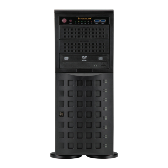
Chapter 1: Introduction 1.2 System Features The CSE-745BTS-R1K23BP3 is a tower chassis that can also be configured as a 4U rackmount. The following views of the system display the main features. Front View Control Panel 5.25" Drive Bay 3.5" Hard Drive Bays Drive LED Indicators Lock Feet... -
Page 11: Control Panel
Chapter 1: Introduction Control Panel Power Reset Power Failure LED Power LED Information LED HDD LED NIC LED NIC LED Figure 1-2. Control Panel Control Panel Features Feature Description Two front accessible USB 3.0 ports Power Fail LED When this LED flashes, it indicates a power failure in the power supply. Information LED Alerts operator to several states, as noted in the table below. -
Page 12: Rear View
Chapter 1: Introduction Rear View Top Cover Lock Power Supply Power Supply Four USB 3.2 Gen 1 7.1 HD Audio USB 3.2 Gen 2 Figure 1-3. System: Rear View System Features: Rear Feature Description Top Cover Lock Top cover locking mechanism Two 1200W redundant power supplies. -
Page 13: System Architecture
Chapter 1: Introduction 1.3 System Architecture This section covers the printed circuit board (PCB) locations. Board Locations Backplane Motherboard Figure 1-4. Board Locations... -
Page 14: Motherboard Layout
Chapter 1: Introduction 1.4 Motherboard Layout Below is a layout of the X12DAi-N6 motherboard with jumper, connector and LED locations shown. See the table on the following page for descriptions. For detailed descriptions, pinout information and jumper settings, refer to Chapter 4 or the Motherboard Manual. -
Page 15: Quick Reference Table
Chapter 1: Introduction Quick Reference Table Jumper Description Default Setting JBT1 CMOS Clear Open (Normal) JPME1 ME Recovery Pins 1-2 (Normal) JPL1 LAN1 Enable/Disable Pins 1-2 (Enabled) JPL2 LAN2 Enable/Disable Pins 1-2 (Enabled) JWD1 Watchdog Timer Pins 1-2 (Reset) Description Status LE4/LE7 M.2 LED... - Page 16 Chapter 1: Introduction Connector Description JPWR1, JPWR2, JPWR4 8-pin power connectors JPWR3 24-pin ATX power connector JSPDIF_IN, JSPDIF_OUT SPDIF (Sony/Philips Digital Interconnect Format) Audio In/Out connectors JTPM1 Trusted Platform Module/Port 80 Connector JUSB1 (USB0/1/2/3) Back panel USB 3.2 Gen 1 ports JUSBA (USB4) Back panel USB 3.2 Gen 2 Type A port JUSB31_l1 (USB7)
-
Page 17: Motherboard Block Diagram
Chapter 1: Introduction Motherboard Block Diagram X12DAi-N6 CPU1-B1 CPU1-A1 CPU1-D1 CPU1-C1 CPU2-C1 CPU2-D1 CPU2-A1 CPU2-B1 PVCCIN_CPU1 12V_STBY PVCCIN_CPU1 12V_STBY VR13HC VR13HC 7+1 PHASE 7+1 PHASE 270W 270W 10.4/11.2G CPU1 CPU2 DDR4 DDR4 CPU1-F1 CPU1-E1 CPU1-H1 CPU1-G1 CPU2-G1 CPU2-H1 CPU2-E1 CPU2-F1 PECI:30 PECI:31 SOCKET ID:0... -
Page 18: Chapter 2 System Installation
PCBs by their edges and keep them in anti-static bags when not in use. 2.2 Unpacking the System Inspect the box in which the SuperWorkstation SYS-740A-T was shipped, and note if it was damaged in any way. If any equipment appears damaged, file a damage claim with the carrier who delivered it. -
Page 19: System Precautions
Chapter 2: System Installation • In single rack installations, stabilizers should be attached to the rack. In multiple rack in- stallations, the racks should be coupled together. • Always make sure the rack is stable before extending a system or other component from the rack. -
Page 20: Airflow
Chapter 2: System Installation the rack's ambient temperature does not exceed the manufacturer’s maximum rated ambient temperature (TMRA). Airflow Equipment should be mounted into a rack so that the amount of airflow required for safe operation is not compromised. Mechanical Loading Equipment should be mounted into a rack so that a hazardous condition does not arise due to uneven mechanical loading. - Page 21 Chapter 2: System Installation To prevent bodily injury when mounting or servicing this unit in a rack, you must take special precautions to ensure that the system remains stable. The following guidelines are provided to ensure your safety: • This unit should be mounted at the bottom of the rack if it is the only unit in the rack. •...
-
Page 22: Preparing The Chassis For Rackmounting
Chapter 2: System Installation 2.4 Preparing the Chassis for Rackmounting Removing the Top Tower Cover 1. Locate the blue cover lock at the rear of the cover. 2. Slide the lock to the right and push the cover forward. 3. Lift the top cover off the chassis. Figure 2-1. -
Page 23: Installing The Optional Rails
Chapter 2: System Installation 2.5 Installing the Optional Rails This section provides a guideline for installing the rails to the chassis and to the rack with the optional rackmount kit. Identifying the Sections of the Rack Rails The optional rackmount kit includes two rack rail assemblies. Figures 2-2 and 2-3 show the sections of one rail assembly from two different angles. - Page 24 Chapter 2: System Installation Assembling the Outer Rails and the Rack Brackets Each outer rail requires assembly with the rack brackets before mounting onto the rack. 1. Identify the two long brackets for the rear of each rail and the two short brackets for the front of each rail.
- Page 25 Chapter 2: System Installation Releasing the Inner Rail from the Outer Rail 1. Locate the rail assembly. 2. Extend the rail assembly by pulling it outward. 3. Press the quick-release tab. 4. Separate the inner rail from the outer rail assembly. Figure 2-5.
- Page 26 Chapter 2: System Installation Installing the Inner Rails to the Chassis 1. Attach the handles to the front of the chassis with three screws each. 2. Identify the left and right inner rails. They are labeled on the rails and in the figure below.
- Page 27 Chapter 2: System Installation Installing the Outer Rails to the Rack Use the previously assembled outer rails with the rear brackets loosely attached. 1. Adjust the outer rail to fit the rack depth. Align the screw holes in the bracket ears with the holes in the rack post.
-
Page 28: Installing The System Into The Rack
Chapter 2: System Installation 2.6 Installing the System into the Rack With rails attached to both the chassis and the rack, install the system into the rack. 1. Pull the middle rail out of the outer rail and make sure the ball bearing shuttle is locked at the front of the middle rail. - Page 29 Chapter 2: System Installation 3. Insert and tighten the thumbscrews that hold the front of the system to the rack. Figure 2-11. Securing the System to the Rack Note: Figure is for illustrative purposes only. Always install systems to the bottom of a rack first.
- Page 30 Chapter 2: System Installation Removing the Chassis from the Rack Caution! It is dangerous for a single person to off-load the heavy chassis from the rack without assistance. Be sure to have sufficient assistance supporting the chassis when removing it from the rack.
-
Page 31: Control Panel Orientation
Chapter 2: System Installation 2.7 Control Panel Orientation The system can be configured for either tower or system rack orientation. It is shipped in tower mode and can be immediately used as a desktop workstation. To use it in a rack, rotate the module that contains the control panel and the three drive trays ( in Figure 2-12) 90 degrees. - Page 32 Chapter 2: System Installation Rotating the Control Panel/Drive Module for Rack Mounting Power down the system and open the chassis cover. 2. Disconnect any cables from the back of the Control Panel/Drive Module. 3. Push the module release lever to unlock the module. Control Panel/ Drive Module in Rack Mount...
-
Page 33: Chapter 3 Maintenance And Component Installation
Chapter 3: Maintenance and Component Installation Chapter 3 Maintenance and Component Installation This chapter provides instructions on installing and replacing main system components. To prevent compatibility issues, only use components that match the specifications and/or part numbers given. Installation or replacement of most components require that power first be removed from the system. -
Page 34: Accessing The System
Chapter 3: Maintenance and Component Installation 3.2 Accessing the System The CSE-745BTS-R1K23BP3 has removable side and front covers for interior access. Removing the Side Cover 1. Begin by removing power from the system. 2. Push the cover latch button to release the latch handle. 3. -
Page 35: Motherboard Components
Thermal grease is pre-applied on a new heatsink. No additional thermal grease is needed. • Refer to the Supermicro website for updates on processor and memory support. • All graphics in this manual are for illustrations only. Your components may look different. -
Page 36: The 3Rd Gen Intel Xeon Scalable Processor
Chapter 3: Maintenance and Component Installation The 3rd Gen Intel Xeon Scalable Processor Processor Top View 1. The 3rd Gen Intel Xeon Scalable Processor = Cutout = Pin 1 = CPU Key = Cutout = Pin 1 = CPU Key Processor Top View... - Page 37 Chapter 3: Maintenance and Component Installation 2. The Processor Carrier Carrier Top View = Cutout = Pin 1 = CPU Key Carrier Bottom View...
- Page 38 Chapter 3: Maintenance and Component Installation 3. Heatsink Note: Exercise extreme care when handling the heatsink. Pay attention to the edges of heatsink fins which can be sharp! To avoid damaging the heatsink, please do not apply excessive force on the fins when handling the heatsink.
-
Page 39: Overview Of The Cpu Socket
Chapter 3: Maintenance and Component Installation Overview of the CPU Socket The CPU socket is protected by a plastic protective cover. Plastic Protective Cover CPU Socket... -
Page 40: Overview Of The Processor Carrier Assembly
Chapter 3: Maintenance and Component Installation Overview of the Processor Carrier Assembly The processor carrier assembly contains a 3rd Gen Intel Xeon Scalable processor and a processor carrier. Carefully follow the instructions given in the installation section to place a processor into the carrier to create a processor carrier. -
Page 41: Overview Of The Processor Heatsink Module
Chapter 3: Maintenance and Component Installation Overview of the Processor Heatsink Module The Processor Heatsink Module (PHM) contains a heatsink, a processor carrier, and the 3rd Gen Intel Xeon Scalable Processor 1. Heatsink 2. Processor Carrier 3. The 3rd Gen Intel Xeon Scalable Processor Bottom View 4. -
Page 42: Creating The Processor Carrier Assembly
Chapter 3: Maintenance and Component Installation Creating the Processor Carrier Assembly The processor carrier assembly contains a 3rd Gen Intel Xeon Scalable processor and a processor carrier. To create the processor carrier assembly, please follow the steps below: Note: Be sure to follow the ESD precautions to properly prepare yourself for installation. - Page 43 Chapter 3: Maintenance and Component Installation 3. Locate the lever on the CPU socket and press the lever down as shown below. Lever 4. Using Pin 1 as a guide, carefully align the CPU keys (A & B) on the processor against the CPU keys on the carrier (a &...
- Page 44 Chapter 3: Maintenance and Component Installation 6. After the processor is placed inside the carrier, examine the four sides of the processor, making sure that the processor is properly seated on the carrier. Processor Carrier Processor Carrier Assembly Assembly (Bottom View) (Top View)
-
Page 45: Creating The Processor Heatsink Module (Phm)
Chapter 3: Maintenance and Component Installation Creating the Processor Heatsink Module (PHM) After creating the processor carrier assembly, please follow the instructions below to mount the processor carrier into the heatsink to form the processor heatsink module (PHM). Note: If this is a new heatsink, the thermal grease has been pre-applied on the underside. Otherwise, apply the proper amount of thermal grease. -
Page 46: Preparing The Cpu Socket For Installation
Chapter 3: Maintenance and Component Installation Preparing the CPU Socket for Installation This motherboard comes with a plastic protective cover installed on the CPU socket. Remove it from the socket to install the Processor Heatsink Module (PHM). Gently pull up one corner of the plastic protective cover to remove it. -
Page 47: Preparing To Install The Processor Heatsink Module (Phm) Into The Cpu Socket
Chapter 3: Maintenance and Component Installation Preparing to Install the Processor Heatsink Module (PHM) into the CPU Socket After assembling the Processor Heatsink Module (PHM), you are ready to install it into the CPU socket. To ensure the proper installation, please follow the procedures below: 1. -
Page 48: Installing The Processor Heatsink Module (Phm)
Chapter 3: Maintenance and Component Installation Installing the Processor Heatsink Module (PHM) 1. Align peek nut "A", which is next to the triangle (Pin 1) on the heatsink, against threaded fastener "a" on the CPU socket. Then align peek nuts "B", "C", "D" on the heatsink against threaded fasteners "b", "c", "d"... - Page 49 Chapter 3: Maintenance and Component Installation 4. With a T30-bit screwdriver, tighten all peek nuts in the sequence of "A", "B", "C", and "D" with even pressure. To avoid damaging the processor or socket, do not use a force greater than 12 lbf-in when tightening the screws. 5.
-
Page 50: Removing The Processor Heatsink Module From The Cpu Socket
Chapter 3: Maintenance and Component Installation Removing the Processor Heatsink Module from the CPU Socket Before removing the processor heatsink module (PHM) from the motherboard, unplug the AC power cord from all power supplies after shutting down the system. Then follow the steps below: 1. -
Page 51: Removing The Carrier Assembly From The Processor Heatsink Module (Phm)
Chapter 3: Maintenance and Component Installation Removing the Carrier Assembly from the Processor Heatsink Module (PHM) To remove the processor carrier assembly from the PHM, please follow the steps below: 1. Detach four plastic clips (marked a, b, c, d) on the processor carrier assembly from the four corners of heatsink (marked A, B, C, D) in the drawings below. -
Page 52: Removing The Processor From The Processor Carrier Assembly
Chapter 3: Maintenance and Component Installation Removing the Processor from the Processor Carrier Assembly Once you have removed the processor carrier assembly from the PHM, you are ready to remove the processor from the processor carrier by following the steps below. 1. -
Page 53: Memory
Chapter 3: Maintenance and Component Installation 3.4 Memory The X12DAi-N6 motherboard has 16 DIMM slots. It supports up to • 4TB (DDR4 only): 3DS LRDIMM/LRDIMM/3DS RDIMM/RDIMM DDR4 (288-pin) ECC memory with speeds of 3200/2933/2666 MHz. • 4TB (PMem + DDR4): Intel Optane PMem 200 Series with speeds of up to 3200 MHz. Notes: PMem 200 Series are supported on 3rd Gen Intel Xeon Scalable Platinum, Gold and selected Silver processors. -
Page 54: Ddr4 Memory Population Guideline
CPU2: A1, E1, C1, G1, B1, F1, D1, H1 *recommended configurations shaded in orange and marked with an asterisk Note: Memory DIMM capacities larger than 64GB may only be supported under certain conditions, please contact Supermicro technical support for additional information. -
Page 55: Intel Optane Pmem 200 Series
Note: PMem 200 Series are supported on 3rd Gen Intel Xeon Scalable Platinum, Gold and selected Silver processors. PMem may only be supported under certain conditions, please contact Supermicro technical support for additional information. CPU1 PMem Population on 16-DIMM Motherboard... -
Page 56: Dimm Installation
Chapter 3: Maintenance and Component Installation DIMM Installation USB4(3.1) LAN/1/2 USB0/1/2/3(3.0) HEARTBEAT JVGA LEDM1 JUSBA JAUDIO1 JNCSI JUSB1 JLAN1 1. Insert the desired number of DIMMs into the JPCIE1 JPCIE2 JPCIE3 JPCIE4 JPCIE5 JPCIE6 memory slots based on the recommended DIMM population table on page 54. -
Page 57: Dimm Removal
Chapter 3: Maintenance and Component Installation DIMM Removal Press both release tabs on the ends of the DIMM module to unlock it. Once the DIMM module is loosened, remove it from the memory slot. Warning! Please do not use excessive force when pressing the release tabs on the ends of the DIMM socket to avoid causing any damage to the DIMM module or the DIMM socket. -
Page 58: Expansion Card Installation
Chapter 3: Maintenance and Component Installation 3.5 Expansion Card Installation Installing an M.2 Solid State Drive The X12DAi-N6 can accommodate two M.2 solid state drives (SSDs). Each M.2 socket supports NVMe PCIe 4.0 x4 (32 Gb/s) SSD cards in the 2280 or 22110 form factors. The 22110 form factor is recommended because the appropriate standoff comes pre-installed on the motherboard. -
Page 59: Pci Expansion Card Installation
Chapter 3: Maintenance and Component Installation PCI Expansion Card Installation The motherboard supports six expansion cards. Installing Expansion Cards 1. Begin by removing power from the system and remove the side cover. 2. Locate the release tab on the top of the PCI slot bracket. Figure 3-4. - Page 60 Chapter 3: Maintenance and Component Installation 3. Gently apply pressure in the middle of the release tab to unlock the PCI slot bracket. 4. Pull the release tab upward. 5. Remove the screw holding the bracket in place and pull the bracket from the chassis. 6.
-
Page 61: Motherboard Battery
Chapter 3: Maintenance and Component Installation 3.6 Motherboard Battery The motherboard uses non-volatile memory to retain system information when system power is removed. This memory is powered by a lithium battery residing on the motherboard. Replacing the Battery Begin by removing power from the system. -
Page 62: Storage Drives
Chapter 3: Maintenance and Component Installation 3.7 Storage Drives A total of eight drives may be housed in the CSE-745BTS-R1K23BP3 chassis. All drive bays support SATA HDDs by default. Drive bays 0-7 can support SAS HDDs with optional add- on card and cables. Drive bays 0-3 can also support NVMe SSDs with optional cables. See Chapter 6 Optional Components for more information. -
Page 63: Drive Carrier Indicators
Chapter 3: Maintenance and Component Installation Drive Carrier Indicators Each drive carrier has two LED indicators: an activity indicator and a status indicator. The meaning of the status indicator is described in the table below. Drive Carrier LED Indicator Color Blinking Pattern Behavior for Device Blue... -
Page 64: Hot-Swap Drives
Chapter 3: Maintenance and Component Installation Hot-Swap Drives Hot-swap capability depends on the operating system support. Check if a drive is hot- swappable before attempting to remove the drive. If a drive is not hot-swappable, power down the system and remove power before opening the front bezel. Removing a Drive Carrier 1. - Page 65 Chapter 3: Maintenance and Component Installation Removing 2.5" Drive from the Converter Tray 1. Press down on the release tab untils the drive pops up from the tray. 2. Remove the 2.5" drive from the tray. Figure 3-10. Removing a 2.5" Drive from the Carrier Removing the Converter Tray 1.
- Page 66 2. Install the 3.5" drive into the drive carrier and reinstall the screws. Figure 3-12. Installing or Removing a 3.5" Drive Note: Enterprise level hard disk drives are recommended for use in Supermicro chassis and systems. For information on recommended HDDs, visit the Supermicro website at http://www.
-
Page 67: System Cooling
Chapter 3: Maintenance and Component Installation 3.8 System Cooling Three 8-cm chassis cooling fans (located in the center of the chassis) provide cooling airflow while two 8-cm exhaust fans expel hot air from the chassis. The chassis is also fitted with an air shroud to balance the overall system thermal performance. - Page 68 Chapter 3: Maintenance and Component Installation Replacing Mid-Chassis Cooling Fans 1. Begin by removing the side cover. 2. Depress the locking tab on the failed fan. 3. With the tab depressed, pull the unit straight out. The wiring for these fans has been designed to detach automatically.
-
Page 69: Air Shroud
Chapter 3: Maintenance and Component Installation Air Shroud The air shroud balances the system's thermal performance and should be in place during normal operation. Under most circumstances you will not need to remove the air shroud to perform any service on the system. However, if you wish to temporarily remove it, please follow the procedure below. - Page 70 Chapter 3: Maintenance and Component Installation Installing the Air Shroud 1. Drop the air shroud into place. 2. Line up the internal divider walls and both sides of the air shroud. 3. Line up the rear of the air shroud. Figure 3-17.
-
Page 71: Power Supply
A failed power supply can be replaced while the system is running. Replacement units can be ordered directly from Supermicro. Note: Full redundancy is based on system configuration and application load. -
Page 72: Storage Drive Cable Routing Diagrams
Chapter 3: Maintenance and Component Installation 3.10 Storage Drive Cable Routing Diagrams The system supports eight hot-swap 3.5"/2.5" SAS/SATA storage drives. SAS can be supported with an optional controller card and cables. NVMe support just require additional cables (refer to the optional parts list for more details). Below are the cable routing diagrams for each of these storage configurations. -
Page 73: Storage Aoc Drive Bay Cable Routing
Chapter 3: Maintenance and Component Installation Storage AOC Drive Bay Cable Routing Figure 3-20. Cable Routing Diagram Eight SAS Drives Drive Configuration Drive Bay 0-7 CBL-SAST-0593 or CBL-SAST-1264-100 8 SAS (The cable depends on the SAS controller. See the optional parts list in Chapter 6 more details.) -
Page 74: Pch Sata Drive Bay Cable Routing
Chapter 3: Maintenance and Component Installation PCH SATA Drive Bay Cable Routing Figure 3-21. Cable Routing Diagram PCH SATA Drives Drive Configuration Drive Bay 0-7 8 PCH SATA CBL-SAST-0631... -
Page 75: Chapter 4 Motherboard Connections
Chapter 4: Motherboard Connections Chapter 4 Motherboard Connections This section describes the connections on the motherboard and provides pinout definitions. Note that depending on how the system is configured, not all connections are required. The LEDs on the motherboard are also described here. A motherboard layout indicating component locations may be found in Chapter 1. -
Page 76: Headers And Connectors
Chapter 4: Motherboard Connections 4.2 Headers and Connectors Fan Headers There are eight 4-pin fan headers (FAN1 ~ FAN7, FANA) on the motherboard. All these 4-pin fan headers are backwards compatible with the traditional 3-pin fans. However, fan speed control is available for 4-pin fans only by Thermal Management via the BMC interface. Refer to the table below for pin definitions. - Page 77 Port 80 connection. Use this header to enhance system performance and data security. Refer to the table below for pin definitions. Please go to the following link for more information on the TPM: http://www.supermicro.com/manuals/other/TPM.pdf. Trusted Platform Module Header Pin Definitions...
- Page 78 C) headers (JNVI2C), used for PCIe SMBus clock and data connections, provide hot-plug support via a dedicated SMBus interface. This feature is only available for a Supermicro complete system with an SMCI-proprietary NVMe add-on card and cable installed. See the table below for pin definitions.
- Page 79 Chapter 4: Motherboard Connections M.2 Slot The X12DAi-N6 motherboard has two M.2 slot (JM2_1 and JM2_2). M.2 allows for a variety of card sizes, increased functionality, and spatial efficiency. The M.2 socket on the motherboard supports PCIe 4.0 x4 (32 Gb/s) SSD cards in the 2280 and 22110 form factors. Note: JM2_2 cannot be used if a graphics card is installed in any of the PCIe slots 1-5.
-
Page 80: Control Panel
JF1 contains header pins for various buttons and indicators that are normally located on a control panel at the front of the chassis. These connectors are designed specifically for use with Supermicro chassis. See the figure below for the descriptions of the front control panel buttons and LED indicators. - Page 81 Chapter 4: Motherboard Connections Front Control Panel LEDs Power Button Ground Reset Button Ground Power Fail (for LED6) 3.3V Red+ Blue+ (Blue LED_Cathode_UID) (Red OH/Fan Fail/PWR Fail for LED5/Blue UID LED) NIC2 (Activity) LED NIC2 (Link) LED NIC1 (Link) LED NIC1 (Activity) LED ID_UID/3.3V Stby HDD LED...
- Page 82 Chapter 4: Motherboard Connections Power On & BMC/BIOS Status LED Button The Power On and BMC/BIOS Status LED button is located on pins 1 and 2 of JF1. Momentarily contacting both pins will power on/off the system or display BMC/BIOS status. Refer to the tables below for more information.
- Page 83 Chapter 4: Motherboard Connections Power Fail LED The Power Fail LED connection is located on pins 5 and 6 of JF1. When this LED turns solid red, it indicates a power failure. Refer to the table below for pin definitions. Power Fail LED Pin Definitions (JF1) Pin#...
- Page 84 Chapter 4: Motherboard Connections NIC1/NIC2 (LAN1/LAN2) The NIC (Network Interface Controller) LED connection for LAN port 1 is located on pins 11 and 12 of JF1, and LAN port 2 is on pins 9 and 10. Refer to the tables below for pin definitions. LAN1/LAN2 LED LAN1/LAN2 LED Pin Definitions (JF1)
-
Page 85: Input/Output Ports
Chapter 4: Motherboard Connections 4.3 Input/Output Ports LAN/1/2 USB4(3.1) USB0/1/2/3(3.0) HEARTBEAT JVGA LEDM1 JUSBA JAUDIO1 JNCSI JUSB1 JLAN1 JPCIE1 JPCIE2 JPCIE3 JPCIE4 JPCIE5 JPCIE6 COM1 JNVI2C JNVME2 JIPMB1 MH17 MH18 JM2_2 BIOS LICENSE CPU2 MAC CODE X12DAi-N JM2_1 BAR CODE REV:1.01 DESIGNED IN USA MH15... - Page 86 Chapter 4: Motherboard Connections VGA Port A video (VGA) port is located next to LAN2 on the I/O back panel. Refer to the board layout below for the location. 7.1 HD (High-Definition) Audio This motherboard features a 7.1 Channel High-Definition Audio (HDA) codec that provides 8 DAC channels.
- Page 87 Chapter 4: Motherboard Connections Ethernet Ports Two Gigabit Ethernet ports (LAN1, LAN2) are located on the I/O back panel. These Ethernet ports support 1GbE LAN connections on the X12DAi-N6. All of these ports accept RJ45 cables. Please refer to the LED Indicator section for LAN LED information. LAN Port Pin Definition Pin#...
-
Page 88: Jumpers
Chapter 4: Motherboard Connections 4.4 Jumpers Explanation of Jumpers To modify the operation of the motherboard, jumpers are used to choose between optional settings. Jumpers create shorts between two pins to change the function associated with it. Pin 1 is identified with a square solder pad on the printed circuit board. See the motherboard layout page for jumper locations. - Page 89 Chapter 4: Motherboard Connections Watchdog Watchdog (JWD1) is a system monitor that can reboot the system when a software application hangs. Close pins 1-2 to reset the system if an application hangs. Close pins 2-3 to generate a non-maskable interrupt (NMI) signal for the application that hangs. Refer to the table below for jumper settings.
-
Page 90: Led Indicators
Chapter 4: Motherboard Connections 4.5 LED Indicators LAN LEDs Two LAN ports (LAN 1 and LAN 2) are located on the I/O back panel of the motherboard. Each Ethernet LAN port has two LEDs. The solid green LED indicates activity, while the other Link LED may be green, amber, or off to indicate the speed of the connection. - Page 91 Chapter 4: Motherboard Connections BMC Heartbeat LED A BMC Heartbeat LED is located at LEDM1 on the motherboard. When LEDM1 is blinking, the BMC is functioning normally. Refer to the table below for more information. BMC Heartbeat LED Indicator LED Color Definition Green: BMC Normal...
-
Page 92: Chapter 5 Software
USB/SATA DVD drive, or a USB flash drive, or the BMC KVM console. 2. Retrieve the proper RST/RSTe driver. Go to the Supermicro web page for your motherboard and click on "Download the Latest Drivers and Utilities", select the proper driver, and copy it to a USB flash drive. - Page 93 Chapter 5: Software 4. During Windows Setup, continue to the dialog where you select the drives on which to install Windows. If the disk you want to use is not listed, click on “Load driver” link at the bottom left corner. Figure 5-2.
-
Page 94: Driver Installation
The Supermicro website contains drivers and utilities for your system at https://www. supermicro.com/wdl/driver. Some of these must be installed, such as the chipset driver. After accessing the website, go into the CDR_Images (in the parent directory of the above link) and locate the ISO file for your motherboard. Download this file to a USB flash drive or a DVD. -
Page 95: Superdoctor ® 5
5.3 SuperDoctor ® The Supermicro SuperDoctor 5 is a program that functions in a command-line or web-based interface for Windows and Linux operating systems. The program monitors such system health information as CPU temperature, system voltages, system power consumption, fan speed, and provides alerts via email or Simple Network Management Protocol (SNMP). -
Page 96: Bmc
There are several BIOS settings that are related to BMC. For general documentation and information on BMC, visit our website at: www.supermicro.com/en/solutions/management-software/bmc-resources BMC ADMIN User Password For security, each system is assigned a unique default BMC password for the ADMIN user. -
Page 97: Chapter 6 Optional Components
Enables the 8x hot-swap drive bays to support controller kit (backplane is 16DD-P and 1x CBL- SAS drives Gen3) SAST-1264-100 Supermicro System Managment Software Suite Management Software SFT-DCMS-SINGLE - 1 per node 9.4K RPM, Hot-swappable Middle Cooling Middle Fan FAN-0182L4... -
Page 98: Tpm Security Module
The JTPM1 header is used to connect a Trusted Platform Module (TPM). A TPM is a security device that supports encryption and authentication in hard drives. It enables the motherboard to deny access if the TPM associated with the hard drive is not installed in the system. Details and installation procedures are at: http://www.supermicro.com/manuals/other/TPM.pdf. • AOM-TPM-9670V... -
Page 99: Chapter 7 Troubleshooting And Support
Chapter 7: Troubleshooting and Support Chapter 7 Troubleshooting and Support 7.1 Information Resources Website A great deal of information is available on the Supermicro website, supermicro.com. Figure 7-1. Supermicro Website • Specifications for servers and other hardware are available by clicking Products. •... -
Page 100: Bmc Interface
Security Center for recent security notices Supermicro Phone and Addresses 7.2 BMC Interface The system supports the Baseboard Management Controller (BMC) interface. BMC is used to provide remote access, monitoring and management. There are several BIOS settings that are related to BMC. -
Page 101: Troubleshooting Procedures
Chapter 7: Troubleshooting and Support 7.3 Troubleshooting Procedures Use the following procedures to troubleshoot your system. If you have followed all of the procedures below and still need assistance, refer to the Technical Support Procedures Returning Merchandise for Service sections in this chapter. Power down the system before changing any non hot-swap hardware components. -
Page 102: No Video
Chapter 7: Troubleshooting and Support • Make sure that the power connector is connected to the power supply. • Check that the motherboard battery still supplies ~3VDC. If it does not, replace it. • Check that the system input voltage is 100-120v or 180-240v. •... -
Page 103: When The System Becomes Unstable
Also check the Control panel Overheat LED. • Adequate power supply: Make sure that the power supply provides adequate power to the system. Make sure that all power connectors are connected. Refer to the Supermicro website for the minimum power requirements. •... -
Page 104: Bios Error Beep (Post) Codes
When BIOS performs the Power On Self Test, it writes checkpoint codes to I/O port 0080h. If the computer cannot complete the boot process, a diagnostic card can be attached to the computer to read I/O port 0080h (Supermicro p/n AOC-LPC80-20). For information on AMI updates, please refer to http://www.ami.com/products/. -
Page 105: Crash Dump Using Bmc
In the event of a processor internal error (IERR) that crashes your system, you may want to provide information to support staff. You can download a crash dump of status information using BMC. The BMC manual is available at https://www.supermicro.com/manuals/other/ BMC_Users_Guide_X12_H12.pdf. Check BMC Error Log 1. -
Page 106: Uefi Bios Recovery
Warning: Do not upgrade the BIOS unless your system has a BIOS-related issue. Flashing the wrong BIOS can cause irreparable damage to the system. In no event shall Supermicro be liable for direct, indirect, special, incidental, or consequential damages arising from a BIOS update. - Page 107 USB device or a writable CD/DVD. Note 1: If you cannot locate the "Super.ROM" file in your drive disk, visit our website at www.supermicro.com to download the BIOS package. Extract the BIOS binary image into a USB flash device and rename it "Super.ROM" for the BIOS recovery use.
- Page 108 Chapter 7: Troubleshooting and Support Note: At this point, you may decide if you want to start the BIOS recovery. If you decide to proceed with BIOS recovery, follow the procedures below. 4. When the screen as shown above displays, use the arrow keys to select the item "Proceed with flash update"...
- Page 109 Chapter 7: Troubleshooting and Support 7. Press <Del> continuously during system boot to enter the BIOS Setup utility. From the top of the tool bar, select Boot to enter the submenu. From the submenu list, select Boot Option #1 as shown below. Then, set Boot Option #1 to [UEFI AP:UEFI: Built-in EFI Shell]. Press <F4>...
- Page 110 Chapter 7: Troubleshooting and Support Note: Do not interrupt this process until the BIOS flashing is complete. 9. The screen above indicates that the BIOS update process is complete. When you see the screen above, unplug the AC power cable from the power supply, clear CMOS, and plug the AC power cable in the power supply again to power on the system.
-
Page 111: Cmos Clear
Chapter 7: Troubleshooting and Support 7.7 CMOS Clear JBT1 is used to clear CMOS, which will also clear any passwords. Instead of pins, this jumper consists of contact pads to prevent accidentally clearing the contents of CMOS. To Clear CMOS 1. -
Page 112: Where To Get Replacement Components
7.8 Where to Get Replacement Components If you need replacement parts for your system, to ensure the highest level of professional service and technical support, purchase exclusively from our Supermicro Authorized Distributors/System Integrators/Resellers. A list can be found at: http://www.supermicro.com. -
Page 113: Vendor Support Filing System
For issues related to Red Hat Enterprise Linux, since it is a subscription based OS, contact your account representative. 7.10 Feedback Supermicro values your feedback as we strive to improve our customer experience in all facets of our business. Please email us at techwriterteam@supermicro.com to provide feedback on our manuals. -
Page 114: Appendix A Standardized Warning Statements For Ac Systems
Supermicro's Technical Support department for assistance. Only certified technicians should attempt to install or configure components. Read this appendix in its entirety before installing or configuring components in the Supermicro chassis. These warnings may also be found on our website at http://www.supermicro.com/about/... - Page 115 Appendix A: Warning Statements Warnung WICHTIGE SICHERHEITSHINWEISE Dieses Warnsymbol bedeutet Gefahr. Sie befinden sich in einer Situation, die zu Verletzungen führen kann. Machen Sie sich vor der Arbeit mit Geräten mit den Gefahren elektrischer Schaltungen und den üblichen Verfahren zur Vorbeugung vor Unfällen vertraut. Suchen Sie mit der am Ende jeder Warnung angegebenen Anweisungsnummer nach der jeweiligen Übersetzung in den übersetzten Sicherheitshinweisen, die zusammen mit diesem Gerät ausgeliefert wurden.
- Page 116 Appendix A: Warning Statements . ٌ ا ك ً ف حالة و ٌ يك أى تتسبب ف اصابة جسذ ة ٌ هذا الزهز ع ٌ خطز !تحذ ز قبل أى تعول عىل أي هعذات،يك عىل علن بالوخاطز ال ا ٌجوة عي الذوائز ٍ...
- Page 117 Appendix A: Warning Statements Warnung Vor dem Anschließen des Systems an die Stromquelle die Installationsanweisungen lesen. ¡Advertencia! Lea las instrucciones de instalación antes de conectar el sistema a la red de alimentación. Attention Avant de brancher le système sur la source d'alimentation, consulter les directives d'installation. .יש...
- Page 118 Appendix A: Warning Statements Warnung Dieses Produkt ist darauf angewiesen, dass im Gebäude ein Kurzschluss- bzw. Überstromschutz installiert ist. Stellen Sie sicher, dass der Nennwert der Schutzvorrichtung nicht mehr als: 250 V, 20 A beträgt. ¡Advertencia! Este equipo utiliza el sistema de protección contra cortocircuitos (o sobrecorrientes) del edificio.
- Page 119 Appendix A: Warning Statements 電源切断の警告 システムコンポーネントの取り付けまたは取り外しのために、 シャーシー内部にアクセスするには、 システムの電源はすべてのソースから切断され、 電源コードは電源モジュールから取り外す必要が あります。 警告 在你打开机箱并安装或移除内部器件前,必须将系统完全断电,并移除电源线。 警告 在您打開機殼安裝或移除內部元件前,必須將系統完全斷電,並移除電源線。 Warnung Das System muss von allen Quellen der Energie und vom Netzanschlusskabel getrennt sein, das von den Spg.Versorgungsteilmodulen entfernt wird, bevor es auf den Chassisinnenraum zurückgreift, um Systemsbestandteile anzubringen oder zu entfernen. ¡Advertencia! El sistema debe ser disconnected de todas las fuentes de energía y del cable eléctrico quitado de los módulos de fuente de alimentación antes de tener acceso el interior del chasis para...
- Page 120 Appendix A: Warning Statements يجب فصم اننظاو من جميع مصادر انطاقت وإ ز انت سهك انكهرباء من وحدة امداد انطاقت قبم انىصىل إىن امنناطق انداخهيت نههيكم نتثبيج أو إ ز انت مكىناث الجهاز 경고! 시스템에 부품들을 장착하거나 제거하기 위해서는 섀시 내부에 접근하기 전에 반드시 전원 공급장치로부터...
- Page 121 Appendix A: Warning Statements Attention Il est vivement recommandé de confier l'installation, le remplacement et la maintenance de ces équipements à des personnels qualifiés et expérimentés. !אזהרה .צוות מוסמך בלבד רשאי להתקין, להחליף את הציוד או לתת שירות עבור הציוד واملدربيه...
- Page 122 Appendix A: Warning Statements Warnung Diese Einheit ist zur Installation in Bereichen mit beschränktem Zutritt vorgesehen. Der Zutritt zu derartigen Bereichen ist nur mit einem Spezialwerkzeug, Schloss und Schlüssel oder einer sonstigen Sicherheitsvorkehrung möglich. ¡Advertencia! Esta unidad ha sido diseñada para instalación en áreas de acceso restringido. Sólo puede obtenerse acceso a una de estas áreas mediante la utilización de una herramienta especial, cerradura con llave u otro medio de seguridad.
- Page 123 Appendix A: Warning Statements Battery Handling Warning! There is the danger of explosion if the battery is replaced incorrectly. Replace the battery only with the same or equivalent type recommended by the manufacturer. Dispose of used batteries according to the manufacturer's instructions 電池の取り扱い...
- Page 124 Appendix A: Warning Statements هناك خطر من انفجار يف حالة اسحبذال البطارية بطريقة غري صحيحة فعليل اسحبذال البطارية فقط بنفس النىع أو ما يعادلها مام أوصث به الرشمة املصنعة جخلص من البطاريات املسحعملة وفقا لحعليامت الرشمة الصانعة 경고! 배터리가 올바르게 교체되지 않으면 폭발의 위험이 있습니다. 기존 배터리와 동일하거나 제 조사에서...
- Page 125 Appendix A: Warning Statements ¡Advertencia! Puede que esta unidad tenga más de una conexión para fuentes de alimentación. Para cortar por completo el suministro de energía, deben desconectarse todas las conexiones. Attention Cette unité peut avoir plus d'une connexion d'alimentation. Pour supprimer toute tension et tout courant électrique de l'unité, toutes les connexions d'alimentation doivent être débranchées.
- Page 126 Appendix A: Warning Statements Backplane Voltage Warning! Hazardous voltage or energy is present on the backplane when the system is operating. Use caution when servicing. バックプレーンの電圧 システムの稼働中は危険な電圧または電力が、 バックプレーン上にかかっています。 修理する際には注意く ださい。 警告 当系统正在进行时,背板上有很危险的电压或能量,进行维修时务必小心。 警告 當系統正在進行時,背板上有危險的電壓或能量,進行維修時務必小心。 Warnung Wenn das System in Betrieb ist, treten auf der Rückwandplatine gefährliche Spannungen oder Energien auf.
- Page 127 Appendix A: Warning Statements هناك خطز مه التيار الكهزبايئ أوالطاقة املىجىدة عىل اللىحة عندما يكىن النظام يعمل كه حذ ر ا عند خدمة هذا الجهاس 경고! 시스템이 동작 중일 때 후면판 (Backplane)에는 위험한 전압이나 에너지가 발생 합니다. 서비스 작업 시 주의하십시오. Waarschuwing Een gevaarlijke spanning of energie is aanwezig op de backplane wanneer het systeem in gebruik is.
- Page 128 Appendix A: Warning Statements תיאום חוקי החשמל הארצי !אזהרה .התקנת הציוד חייבת להיות תואמת לחוקי החשמל המקומיים והארציים تركيب املعدات الكهربائية يجب أن ميتثل للقىاويه املحلية والىطىية املتعلقة بالكهرباء 경고! 현 지역 및 국가의 전기 규정에 따라 장비를 설치해야 합니다. Waarschuwing Bij installatie van de apparatuur moet worden voldaan aan de lokale en nationale elektriciteitsvoorschriften.
- Page 129 Appendix A: Warning Statements Attention La mise au rebut ou le recyclage de ce produit sont généralement soumis à des lois et/ou directives de respect de l'environnement. Renseignez-vous auprès de l'organisme compétent. סילוק המוצר !אזהרה .סילוק סופי של מוצר זה חייב להיות בהתאם להנחיות וחוקי המדינה التخلص...
- Page 130 Appendix A: Warning Statements Warnung Gefährlich Bewegende Teile. Von den bewegenden Lüfterblätter fern halten. Die Lüfter drehen sich u. U. noch, wenn die Lüfterbaugruppe aus dem Chassis genommen wird. Halten Sie Finger, Schraubendreher und andere Gegenstände von den Öffnungen des Lüftergehäuses entfernt.
- Page 131 Verbindungskabeln, Stromkabeln und/oder Adapater, die Ihre örtlichen Sicherheitsstandards einhalten. Der Gebrauch von anderen Kabeln und Adapter können Fehlfunktionen oder Feuer verursachen. Die Richtlinien untersagen das Nutzen von UL oder CAS zertifizierten Kabeln (mit UL/CSA gekennzeichnet), an Geräten oder Produkten die nicht mit Supermicro gekennzeichnet sind.
- Page 132 .قيرح وأ لطع يف ببستي دق ىرخأ تالوحمو تالباك يأ مادختسا .ميلسلا سباقلاو لصوملا مجح لبق نم ةدمتعملا تالباكلا مادختسا تادعملاو ةيئابرهكلا ةزهجألل ةمالسلا نوناق رظحيUL وأCSA ( ةمالع لمحت يتلاوUL/CSA) لبق نم ةددحملاو ةينعملا تاجتنملا ريغ ىرخأ تادعم يأ عمSupermicro.
- Page 133 사항을 준수하여 제공되거나 지정된 연결 혹은 구매 케이블, 전원 케이블 및 AC 어댑터를 사용하십시오. 다른 케이블이나 어댑터를 사용하면 오작동이나 화재가 발생할 수 있습니다. 전기 용품 안전법은 UL 또는 CSA 인증 케이블 (코드에 UL / CSA가 표시된 케이블)을 Supermicro 가 지정한 제품 이외의 전기 장치에 사용하는 것을 금지합니다. Stroomkabel en AC-Adapter...
-
Page 134: Appendix B System Specifications
Dual 3rd Gen Intel Xeon Scalable Processors (Socket P+) with up to 40 cores and a thermal design power (TDP) of up to 270W Note: Refer to the motherboard specifications page on our website for updates to supported processors. Certain CPU SKUs are conditionally supported. Please contact Supermicro Technical Support for additional information about specialized system optimization. Chipset... - Page 135 Appendix B: System Specifications System Cooling Three 8-cm internal hot-swappable fans, two 8-cm hot-swappable fans, one air shroud, two active CPU heatsinks (p/n SNK- P0080AP4) Power Supply Model: PWS-1K23A-SQ, 1200 W redundant modules, 80Plus Titanium level AC Input 100-127 Vac, 9-7.5A, 50-60 Hz 200-240 Vac, 6-5A, 50-60 Hz +12V Max: 66.7 A, Min: 0 A (100 Vac–127 Vac)
Need help?
Do you have a question about the SuperWorkstation SYS-740A-T and is the answer not in the manual?
Questions and answers