Table of Contents
Advertisement
Advertisement
Table of Contents

Subscribe to Our Youtube Channel
Related Manuals for Supermicro SuperWorkstation 7049GP-TRT


Summary of Contents for Supermicro SuperWorkstation 7049GP-TRT
- Page 1 SuperWorkstation 7049GP-TRT USER’S MANUAL Revision 1.0c...
- Page 2 State of California, USA. The State of California, County of Santa Clara shall be the exclusive venue for the resolution of any such disputes. Supermicro's total liability for all claims will not exceed the price paid for the hardware product.
- Page 3 If you have any questions, please contact our support team at: support@supermicro.com. This manual may be periodically updated without notice. Please check the Supermicro website for possible updates to the manual revision level. Warnings Special attention should be given to the following symbols used in this manual.
-
Page 4: Table Of Contents
SuperWorkstation 7049GP-TRT User's Manual Contents Chapter 1 Introduction 1.1 Overview ..........................7 1.2 Unpacking the System ......................7 1.3 System Features ........................8 1.4 Server Chassis Features ......................9 Control Panel ........................9 Front Features ........................11 Rear Features ........................12 1.5 Motherboard Layout ......................13 Quick Reference Table ......................14 Chapter 2 Workstation Setup 2.1 Overview ..........................17... - Page 5 Preface Air Shroud ........................30 System Cooling .........................31 System Fan Failure ......................31 Replacing System Fans ....................31 Chapter 4 Motherboard Connections 4.1 Power Connections ......................33 4.2 Headers and Connectors ....................34 4.3 Ports ...........................40 Rear I/O Ports ........................40 4.4 Jumpers ..........................43 Explanation of Jumpers ....................43 4.5 LED Indicators ........................46 Chapter 5 Software 5.1 OS Installation ........................47...
- Page 6 SuperWorkstation 7049GP-TRT User's Manual Contacting Supermicro Headquarters Address: Super Micro Computer, Inc. 980 Rock Ave. San Jose, CA 95131 U.S.A. Tel: +1 (408) 503-8000 Fax: +1 (408) 503-8008 Email: marketing@supermicro.com (General Information) support@supermicro.com (Technical Support) Website: www.supermicro.com Europe Address: Super Micro Computer B.V.
-
Page 7: Chapter 1 Introduction
Chapter 1: Introduction Chapter 1 Introduction 1.1 Overview This chapter provides a brief outline of the functions and features of the 7049GP-TRT. The 7049GP-TRT is based on the X11DPG-QT motherboard and the SC-747BTS-R2K20BP chassis. In addition to the motherboard and chassis, several important parts that are included with the system are listed below. -
Page 8: System Features
SuperWorkstation 7049GP-TRT User's Manual 1.3 System Features The following table provides you with an overview of the main features of the 7049GP-TRT. Please refer to Appendix C for additional specifications. System Features Motherboard X11DPG-QT Chassis SC-747BTS-R2K20BP Intel® Xeon® Scalable Processors... -
Page 9: Server Chassis Features
Chapter 1: Introduction 1.4 Server Chassis Features Control Panel The switches and LEDs located on the control panel are described below. See Chapter 4 for details on the control panel connections. Figure 1-1. Control Panel View... - Page 10 SuperWorkstation 7049GP-TRT User's Manual Control Panel Features Item Feature Description The main power switch is used to apply or remove power from the power supply to the server. Turning off system power with this button Power Button removes the main power but maintains standby power. To perform many maintenance tasks, you must unplug system before servicing.
-
Page 11: Front Features
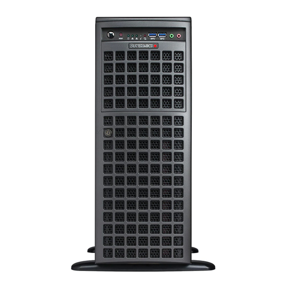
Chapter 1: Introduction Front Features The SC-747BTS-R2K20BP is 4U rackmount/tower chassis See the illustration below for the features included on the front of the chassis. Figure 1-2. Chassis Front View Front Chassis Features Item Feature Description Control Panel Front control panel (see preceding page). Bezel Lock Locks the bezel for secure access. -
Page 12: Rear Features
SuperWorkstation 7049GP-TRT User's Manual Rear Features The illustration below shows the features included on the rear of the chassis. Figure 1-3. Chassis Rear View Rear Chassis Features Item Feature Description Power 2x 2200W redundant power supply with PMBus Serial Port Two USB 3.0 ports and two USB 2.0 ports... -
Page 13: Motherboard Layout
Chapter 1: Introduction 1.5 Motherboard Layout Below is a layout of the X11DPG-QT with jumper, connector and LED locations shown. See the table on the following page for descriptions. For detailed descriptions, pinout information and jumper settings, refer to Chapter 4. JUIDB1 COM1 (UID) -
Page 14: Quick Reference Table
SuperWorkstation 7049GP-TRT User's Manual Quick Reference Table Jumper Description Default Setting JBT1 CMOS Clear Open (Normal) JHD_AC1 AC97/High Definition Audio Enable Off (HD Enabled) JPAC1 Audio Enable Pins 1-2 (Enabled) JPME2 ME Manufacturing Mode Pins 1-2 (Normal) JPTG1 Onboard 10Gb LAN1/2 Enable/Disable... - Page 15 Chapter 1: Introduction Connector Description JSTBY1 Standby Power Connector JTAG_HFI1 HFI Debug Port for Fabric CPU JTBT1 General Purpose Header for Thunderbolt Add-on Card JTPM1 Trusted Platform Module/Port 80 connector JUIDB1 UID (Unit Identifier) Switch LAN1/2 LAN Ports PCI-E M.2 Connector, small form factor devices and other portable devices for High speed NVMe M.2 CONNECTOR SSDs S-SATA4/S-SATA5...
- Page 16 SuperWorkstation 7049GP-TRT User's Manual JPCIE8 x 16 JPCIE6 32GB/s 32GB/s Slot 8 Slot 6 VCCP1&2 PCIE 3.0 x16 PCIE 3.0 x16 VR13 6+1 PHASE 205W JPCIE10 JPCIE11 32GB/s Slot 10 Slot 11 PCIE 3.0 x4 PCIE 3.0 x16 PE2 PE1 DMI...
-
Page 17: Chapter 2 Workstation Setup
Chapter 2: Server Installation Chapter 2 Workstation Setup 2.1 Overview This chapter provides advice setting up your system. If your system is not already fully integrated with processors, system memory etc., refer to Chapter 3 for details on installing those specific components. Caution: Electrostatic Discharge (ESD) can damage electronic components. -
Page 18: Chapter 3 Maintenance And Component Installation
SuperWorkstation 7049GP-TRT User's Manual Chapter 3 Maintenance and Component Installation This chapter provides instructions on installing and replacing main system components. To prevent compatibility issues, only use components that match the specifications and/or part numbers given. Installation or replacement of most components require that power first be removed from the system. -
Page 19: Motherboard Components
• Use an Intel-certified multi-directional heatsink. • Refer to the Supermicro website for updates on CPU support. • Always connect the power cord last, and always remove it before adding, removing, or changing any hardware components. Please note that the processor and heatsink should be assembled together first to form the Processor Heatsink Module (PHM), and then install the entire PHM into the CPU socket. -
Page 20: Overview Of The Processor Socket Assembly
SuperWorkstation 7049GP-TRT User's Manual Overview of the Processor Socket Assembly The processor socket assembly contains 1) the Intel 81xx/61xx/51xx/41xx/31xx processor, 2) the narrow processor clip, 3) the dust cover, and 4) the CPU socket. 1. The 81xx/61xx/51xx/41xx/31xx Processor 81xx/61xx/51xx/41xx/31xx (The Processor) 2. -
Page 21: Overview Of The Processor Heatsink Module (Phm)
Chapter 3: Maintenance and Component Installation Overview of the Processor Heatsink Module (PHM) The Processor Heatsink Module (PHM) contains 1) a heatsink, 2) a narrow processor clip, and 3) the 81xx/61xx/51xx/41xx/31xx processor. 1. Heatsink 2. Narrow Processor Clip 3. Intel Processor... -
Page 22: Attaching The Non-F Model Processor To The Narrow Processor Clip To Create The Processor Package Assembly
SuperWorkstation 7049GP-TRT User's Manual Attaching the Non-F Model Processor to the Narrow Processor Clip to Create the Processor Package Assembly To properly install the CPU into the narrow processor clip, please follow the steps below. 1. Locate pin 1 (notch A), which is the triangle located on the top of the narrow processor clip. -
Page 23: Removing The Fan Module
Chapter 3: Maintenance and Component Installation Removing the FAN Module 1. Unplug the fan module connector from the motherboard fan connector. 2. Remove the screw on the fan module to release it from the heatsink. -
Page 24: Attaching The Non-F Model Processor Package Assembly To The Heatsink To Form The Processor Heatsink Module (Phm)
SuperWorkstation 7049GP-TRT User's Manual Attaching the Non-F Model Processor Package Assembly to the Heatsink to Form the Processor Heatsink Module (PHM) After you have made a processor package assembly by following the instructions on the previous page, please follow the steps below to mount the processor package assembly onto the heatsink to create the Processor Heatsink Module (PHM). -
Page 25: Preparing The Cpu Socket For Installation
Chapter 3: Maintenance and Component Installation Preparing the CPU Socket for Installation This motherboard comes with the CPU socket pre-assembled in the factory. The CPU socket contains 1) a dust cover, 2) a socket bracket, 3) the CPU (P0) socket, and 4) a back plate. These components are pre-installed on the motherboard before shipping. -
Page 26: Installing The Processor Heatsink Module (Phm)
SuperWorkstation 7049GP-TRT User's Manual Installing the Processor Heatsink Module (PHM) 1. Once you have assembled the processor heatsink module (PHM) by following the instructions listed on page 29 or page 30, you are ready to install the processor heatsink module (PHM) into the CPU socket on the motherboard. To install the PHM into the CPU socket, follow the instructions below. -
Page 27: Removing The Processor Heatsink Module (Phm) From The Motherboard
Chapter 3: Maintenance and Component Installation Removing the Processor Heatsink Module (PHM) from the Motherboard Before removing the processor heatsink module (PHM), unplug power cord from the power outlet. 1. Using a T30 Torx-bit screwdriver, turn the screws on the PHM counterclockwise to loosen them from the socket, starting with screw marked #4 (in the sequence of 4, 3, 2, 2. -
Page 28: Installing Memory
SuperWorkstation 7049GP-TRT User's Manual Installing Memory 1. Remove power from the system as described in Section 3.1. 2. Starting with the slot in the order described previously, push the release tab outward to unlock it. Notch Release Tab 3. Align the key of the DIMM with the receptive point on the memory slot and with your thumbs on both ends of the module, press it straight down into the slot until the module snaps into place. -
Page 29: Motherboard Battery
Chapter 3: Maintenance and Component Installation Motherboard Battery The motherboard uses non-volatile memory to retain system information when system power is removed. This memory is powered by a lithium battery residing on the motherboard. Replacing the Battery 1. Remove power from the system as described in section 3.1 and remove the node from the chassis. -
Page 30: Air Shroud
SuperWorkstation 7049GP-TRT User's Manual Air Shroud The air shroud is used to concentrate airflow to maximize fan efficiency. The air shroud does not require screws to set up. Installing the Air Shroud 1. Lay the chassis on a flat, stable surface and remove the chassis cover. -
Page 31: System Cooling
Chapter 3: Maintenance and Component Installation System Cooling Heavy-duty fans provide cooling for the chassis. Four fans are located in the mid-section of the chassis, two fans are located in the rear, and two optional fans can be mounted on the external rear of the chassis, required for passive GPUs. - Page 32 SuperWorkstation 7049GP-TRT User's Manual FAN-0114L4 Mid Fan Release Tab FAN-0138L4 Figure 3-3. Mid-System Chassis Fans FAN-0082L4 Rear Fan Release Tab Figure 3-4. Rear System Chassis Fans...
-
Page 33: Chapter 4 Motherboard Connections
Chapter 4: Motherboard Connections Chapter 4 Motherboard Connections This section describes the connections on the motherboard and provides pinout definitions. Note that depending on how the system is configured, not all connections are required. The LEDs on the motherboard are also described here. A serverboard layout indicating component locations may be found in Chapter 1. -
Page 34: Headers And Connectors
SuperWorkstation 7049GP-TRT User's Manual 4.2 Headers and Connectors Fan Headers There are eight fan headers on the motherboard. These are 4-pin fan headers; pins 1-3 are backward compatible with traditional 3-pin fans. The onboard fan speeds are controlled by Thermal Management (via Hardware Monitoring) in the BIOS. When using Thermal Management setting, please use all 3-pin fans or all 4-pin fans. - Page 35 Chapter 4: Motherboard Connections Disk-On-Module Power Connector The Disk-On-Module (DOM) power connectors at JSD1 and JSD2 provide 5V power to a solid-state DOM storage devices connected to one of the SATA ports. See the table below for pin definitions. DOM Power Pin Definitions Pin# Definition...
- Page 36 Intel® C621 chipset. In addition, it also has two S-SATA 3.0 ports (S-SATA4/ S-SATA5) that are supported by the Intel® SCU. S-SATA4/5 can be used with Supermicro SuperDOMs which are yellow SATA DOM connectors with power pins built in, and do not require external power cables.
- Page 37 Chapter 4: Motherboard Connections RAID Key Header A RAID_Key header is located at JRK1 on the motherboard. RAID key is used to support onboard NVMe connections. RAID Key Header Pin Definitions Pin# Definition Ground RAID_KEY_PU Ground PCH_RAID_KEY Audio Front Panel Header A 10-pin audio header (AUDIO_FP) located on the motherboard allows you to use the onboard sound chip (ALC888S) for audio functions.
- Page 38 (BMC) and a Network Interface Controller (NIC) for remote management. For the network sideband interface to work properly, you will need to use a motherboard that supports NC-SI and also need to have a special cable. Please contact Supermicro at www.supermicro.com...
- Page 39 5V STBY Inlet Sensor Header This header (JSEN1) allows BMC to monitor thermal inlet temperature. A special module is required. Please contact Supermicro at www.supermicro.com to purchase the module for this header. Refer to the table below for pin definitions.
-
Page 40: Ports
SuperWorkstation 7049GP-TRT User's Manual 4.3 Ports Rear I/O Ports See the figure below for the locations and descriptions of the various I/O ports on the rear of the motherboard. Figure 4-2. Rear I/O Ports Rear I/O Ports Description Description COM Port 1... - Page 41 Chapter 4: Motherboard Connections LAN Ports Two LAN ports (LAN1, LAN2) are located on the I/O back panel. These ports accept RJ45 type cables. LAN Port Pin Definition Pin# Definition Pin# Definition TX_D1+ BI_D3- TX_D1- RX_D2- RX_D2+ BI_D4+ BI_D3+ BI_D4- Universal Serial Bus (USB) Ports There are two USB 3.0 ports (USB 4/5) located on the I/O back panel.
- Page 42 SuperWorkstation 7049GP-TRT User's Manual Unit Identifier Switch/UID LED Indicator A rear Unit Identifier (UID) switch (JUIDB1) and an rear LED Indicator (LED2) are located on the rear side of the system. The front UID LED is located on Pin 7 of the Front Control Panel (JF1).
-
Page 43: Jumpers
Chapter 4: Motherboard Connections 4.4 Jumpers Explanation of Jumpers To modify the operation of the motherboard, jumpers are used to choose between optional settings. Jumpers create shorts between two pins to change the function associated with it. Pin 1 is identified with a square solder pad on the printed circuit board. See the motherboard layout page for jumper locations. - Page 44 SuperWorkstation 7049GP-TRT User's Manual HD Audio Enable JHD_AC1 allows you to enable or disable the onboard high definition audio support. See the table below for jumper settings HD Audio Enable/Disable Jumper Settings Jumper Setting Definition Open Enabled (Default) Short Disabled Onboard Audio Enable JPAC1 allows you to enable or disable the onboard audio support.
- Page 45 Chapter 4: Motherboard Connections VRM_I2C Jumper Set this jumper (JVRM_SEL1) to Normal (Default) to allow BMC to access VRM controllers. Set this jumper to short pins 2-3 to have VRM code updated by PCH. See the table below for jumper settings. VRM_I2C Jumper Settings Jumper Setting...
-
Page 46: Led Indicators
SuperWorkstation 7049GP-TRT User's Manual 4.5 LED Indicators Dedicated IPMI LAN LEDs A dedicated IPMI LAN port is also included on the motherboard. The amber LED on the right of the IPMI LAN port indicates activity, while the green LED on the left indicates the speed of the connection. -
Page 47: Chapter 5 Software
USB/SATA DVD drive, or a USB flash drive, or the IPMI KVM console. 2. Retrieve the proper RST/RSTe driver. Go to the Supermicro web page for your motherboard and click on "Download the Latest Drivers and Utilities", select the proper driver, and copy it to a USB flash drive. - Page 48 SuperServer 7049GP-TRT User's Manual 4. During Windows Setup, continue to the dialog where you select the drives on which to install Windows. If the disk you want to use is not listed, click on “Load driver” link at the bottom left corner. Figure 5-2.
-
Page 49: Driver Installation
The Supermicro website contains drivers and utilities for your system at https://www. supermicro.com/wftp/driver. Some of these must be installed, such as the chipset driver. After accessing the website, go into the CDR_Images (in the parent directory of the above link) and locate the ISO file for your motherboard. Download this file to to a USB flash drive or a DVD. -
Page 50: Superdoctor ® 5
5.3 SuperDoctor ® The Supermicro SuperDoctor 5 is a program that functions in a command-line or web-based interface for Windows and Linux operating systems. The program monitors such system health information as CPU temperature, system voltages, system power consumption, fan speed, and provides alerts via email or Simple Network Management Protocol (SNMP). -
Page 51: Ipmi
The X11DPG-QT supports the Intelligent Platform Management Interface (IPMI). IPMI is used to provide remote access, monitoring and management. There are several BIOS settings that are related to IPMI. For general documentation and information on IPMI, please visit our website at: http://www.supermicro.com/products/nfo/IPMI.cfm. -
Page 52: Chapter 6 Uefi Bios
Chapter 6: UEFI BIOS Chapter 6 UEFI BIOS 6.1 Introduction This chapter describes the AMIBIOS™ Setup utility for the X11DPG-QT motherboard. The is stored on a chip and can be easily upgraded using a flash program. Note: Due to periodic changes to the BIOS, some settings may have been added or deleted and might not yet be recorded in this manual. -
Page 53: Main Setup
SuperWorkstation 7049GP-TRT User's Manual 6.2 Main Setup When you first enter the AMI BIOS setup utility, you will enter the Main setup screen. You can always return to the Main setup screen by selecting the Main tab on the top of the screen. The Main BIOS setup screen is shown below. -
Page 54: Advanced Setup Configurations
Chapter 6: UEFI BIOS 6.3 Advanced Setup Configurations Use the arrow keys to select Boot Setup and press <Enter> to access the submenu items. Warning: Take caution when changing the Advanced settings. An incorrect value, a very high DRAM frequency, or an incorrect DRAM timing setting may make the system unstable. When this occurs, revert to the default to the manufacture default settings. - Page 55 SuperWorkstation 7049GP-TRT User's Manual INT19 Trap Response Interrupt 19 is the software interrupt that handles the boot disk function. When this item is set to Immediate, the ROM BIOS of the host adaptors will "capture" Interrupt 19 at bootup immediately and allow the drives that are attached to these host adaptors to function as bootable disks.
- Page 56 Chapter 6: UEFI BIOS Throttle on Power Fail Throttling improves reliability and reduces power consumption in the processor via automatic voltage control during processor idle states. Select Enabled to decrease the system power by throttling CPU frequency when one power supply is failed. The options are Disabled and Enabled.
- Page 57 SuperWorkstation 7049GP-TRT User's Manual Intel Virtualization Technology (Available when supported by the CPU) Select Enable to use Intel® Virtualization Technology so that I/O device assignments will be reported directly to the VMM (Virtual Memory Management) through the DMAR ACPI Tables.
- Page 58 Chapter 6: UEFI BIOS Advanced Power Management Configuration Power Technology Use this item to enable power management features. The options are Disable, Energy Efficient, and Custom. Select Energy Efficient to support power-saving mode. Select Custom to customize system power settings. Select Disable to disable power-saving settings.
- Page 59 SuperWorkstation 7049GP-TRT User's Manual Hardware PM State Control (Available when Power Technology is set to Custom) Hardware P-States This feature enables the hardware P-States support. The options are Disable, Native Mode, Out of Band Mode, and Native Mode with No Legacy Support.
- Page 60 Chapter 6: UEFI BIOS Chipset Configuration Warning: Setting the wrong values in the following features may cause the system to malfunc- tion. North Bridge This feature allows the user to configure the following North Bridge settings. UPI Configuration UPI Configuration The following information will be displayed: •...
- Page 61 SuperWorkstation 7049GP-TRT User's Manual Sub NUMA Clustering (SNC) is a feature that breaks up the Last Level Cache (LLC) into clusters based on address range. Each cluster is connected to a subset of the memory controller. Enabling SNC improves average latency and reduces memory access conges- tion to achieve higher performance.
- Page 62 Chapter 6: UEFI BIOS Memory Configuration Integrated Memory Controller (iMC) Enforce POR Select Enable to enforce POR restrictions on DDR4 frequency and voltage programming. The options are POR and Disable. Memory Frequency Use this feature to set the maximum memory frequency for onboard memory modules. The options are Auto, 1866, 2000, 2133, 2200, 2400, 2600, and 2666.
- Page 63 SuperWorkstation 7049GP-TRT User's Manual Memory Topology The item displays the information of onboard memory modules as detected by the BIOS. Memory RAS (Reliability_Availability_Serviceability) Configuration Memory RAS Configuration Setup Use this submenu to configure the following Memory RAS settings.
- Page 64 Chapter 6: UEFI BIOS ADDDC Sparing Adaptive Double Device Data Correction (ADDDC) Sparing detects the predetermined threshold for correctable errors, copying the contents of the failing DIMM to spare memory. The failing DIMM or memory rank will then be disabled. The options are Dis- able and Enable.
- Page 65 SuperWorkstation 7049GP-TRT User's Manual CPU1 SLOT2 PCI-E 3.0 x16 Link Speed Use this feature to select the link speed for the PCIe port. The options are Auto, Gen 1 (2.5 GT/s), Gen 2 (5 GT/s), and Gen 3 (8 GT/s).
- Page 66 Chapter 6: UEFI BIOS CPU1 SLOT9 PCI-E 3.0 x16 Link Speed Use this feature to select the link speed for the PCIe port. The options are Auto, Gen 1 (2.5 GT/s), Gen 2 (5 GT/s), and Gen 3 (8 GT/s). PCI-E Port Link Status PCI-E Port Link Max PCI-E Port Link Speed...
- Page 67 SuperWorkstation 7049GP-TRT User's Manual PCI-E Port Link Status PCI-E Port Link Max PCI-E Port Link Speed PCI-E Port Clocking The options are Distinct and Common. If this item is set to Distinct, this component and the component at the opposite end of the Link are operating with separate refer- ence clock sources.
- Page 68 Chapter 6: UEFI BIOS CPU2 SLOT10 PCI-E 3.0 x16 Link Speed Use this feature to select the link speed for the PCIe port. The options are Auto, Gen 1 (2.5 GT/s), Gen 2 (5 GT/s), and Gen 3 (8 GT/s). PCI-E Port Link Status PCI-E Port Link Max PCI-E Port Link Speed...
- Page 69 SuperWorkstation 7049GP-TRT User's Manual Intel® VT for Directed I/O (VT-d) Intel VT for Directed I/O (VT-d) ® Select Enable to use Intel® Virtualization Technology support for Direct I/O VT-d support by reporting the I/O device assignments to the VMM (Virtual Machine Monitor) through the DMAR ACPI Tables.
- Page 70 Chapter 6: UEFI BIOS *If the item above "Intel® VMD for Volume Management Device" is set to Enable, the following items will be displayed: CPU1 SLOT2 PCI-E 3.0 x16 VMD (Available when the device is detected by the system) Select Enable to use the Intel® Volume Management Device Technology for this device.
- Page 71 SuperWorkstation 7049GP-TRT User's Manual Intel® VMD for Volume Management Device on CPU2 VMD Config for PStack0 Intel® VMD for Volume Management Device Select Enable to use the Intel® Volume Management Device Technology for this stack. The options are Disable and Enable.
- Page 72 Chapter 6: UEFI BIOS *If the item above "Intel® VMD for Volume Management Device" is set to Enable, the following items will be displayed: CPU2 SLOT10 PCI-E 3.0 x16 VMD (Available when the device is detected by the system) Select Enable to use the Intel® Volume Management Device Technology for this device.
- Page 73 SuperWorkstation 7049GP-TRT User's Manual Real USB Wake Up Select Enabled to enable the wake-up function of the USB port. The options are Disabled and Enabled. Front USB Wake Up Select Enabled to enable the wake-up function of the front access USB port. The options are Disabled and Enabled.
- Page 74 Chapter 6: UEFI BIOS SATA HDD Unlock Select Enable to unlock the HDD password. The options are Disable and Enable. Aggressive Link Power Management When this item is set to Enable, the SATA AHCI controller manages the power usage of the SATA link.
- Page 75 SuperWorkstation 7049GP-TRT User's Manual SATA RSTe Boot Info Select Enable to provide the full int13h support for SATA controller attached devices. The options are Disable and Enable. SATA RAID Option ROM/UEFI Driver Select EFI to load the EFI driver for system boot. Select Legacy to load a legacy driver for system boot.
- Page 76 Chapter 6: UEFI BIOS Aggressive Link Power Management When this item is set to Enable, the SATA AHCI controller manages the power usage of the SATA link. The controller will put the link to a low power state when the I/O is inactive for an extended period of time, and the power state will return to normal when the I/O becomes active.
- Page 77 SuperWorkstation 7049GP-TRT User's Manual sSATA RAID Option ROM/UEFI Driver Select EFI to load the EFI driver for system boot. Select Legacy to load a legacy driver for system boot. The options are Disable, EFI, and Legacy. sSATA Port 0~ Port 1 This item displays the information detected on the installed SATA drive on the particular SATA port.
- Page 78 Chapter 6: UEFI BIOS MMIO High Granularity Size Use this item to select the high memory size according to memory-address mapping for the IO hub. The options are 1G, 4G, 16G, 64G, 256G, and 1024G. PCI PERR/SERR Support Select Enabled to activate PCI Error and System Error report handling. The options are Disabled and Enabled.
- Page 79 SuperWorkstation 7049GP-TRT User's Manual Onboard Video Option ROM Select Legacy to boot the system using a legacy video device installed on the motherboard. The options are Disabled, Legacy, and EFI. Network Stack Configuration Network Stack Select Enabled to enable UEFI (Unified Extensible Firmware Interface) for network stack support.
- Page 80 Chapter 6: UEFI BIOS Serial Port 1 Configuration Serial Port 1 Configuration This submenu allows the user the configure settings of Serial Port 1. Serial Port 1 Select Enabled to enable the selected onboard serial port. The options are Disabled and Enabled.
- Page 81 SuperWorkstation 7049GP-TRT User's Manual Serial Port Console Redirection COM1 Console Redirection Select Enabled to enable console redirection support for a serial port specified by the user. The options are Disabled and Enabled. *If the item above is set to Enabled, the following items will become available for user's configuration: Console Redirection Settings...
- Page 82 Chapter 6: UEFI BIOS Stop Bits A stop bit indicates the end of a serial data packet. Select 1 Stop Bit for standard serial data communication. Select 2 Stop Bits if slower devices are used. The options are 1 and 2. Flow Control Use this feature to set the flow control for Console Redirection to prevent data loss caused by buffer overflow.
- Page 83 SuperWorkstation 7049GP-TRT User's Manual *If the item above is set to Enabled, the following items will become available for user's configuration: Console Redirection Settings This feature allows the user to specify how the host computer will exchange data with the client computer, which is the remote computer used by the user.
- Page 84 Chapter 6: UEFI BIOS is full. Send a "Start" signal to start sending data when the receiving buffer is empty. The options are None and Hardware RTS/CTS. VT-UTF8 Combo Key Support Select Enabled to enable VT-UTF8 Combination Key support for ANSI/VT100 terminals. The options are Disabled and Enabled.
- Page 85 SuperWorkstation 7049GP-TRT User's Manual *If the item above is set to Enabled, the following items will become available for user's configuration: Console Redirection Settings This feature allows the user to specify how the host computer will exchange data with the client computer, which is the remote computer used by the user.
- Page 86 Chapter 6: UEFI BIOS WHEA Support Select Enabled to support the Windows Hardware Error Architecture (WHEA) platform and provide a common infrastructure for the system to handle hardware errors within the Windows OS environment to reduce system crashes and to enhance system recovery and health monitoring.
- Page 87 SuperWorkstation 7049GP-TRT User's Manual Platform Hierarchy Use this item to disable or enable platform hierarchy for platform protection. The options are Disabled and Enabled. Storage Hierarchy Use this item to disable or enable storage hierarchy for cryptographic protection. The options are Disabled and Enabled.
-
Page 88: Event Logs
Chapter 6: UEFI BIOS 6.4 Event Logs Use this feature to configure the Event Log settings. Change SMBIOS Event Log Settings Enabling/Disabling Options SMBIOS Event Log Change this item to enable or disable all features of the SMBIOS (System Management BIOS) Event Logging during system boot. - Page 89 SuperWorkstation 7049GP-TRT User's Manual SMBIOS Event Log Standard Settings Log System Boot Event This option toggles the System Boot Event logging to enabled or disabled. The options are Enabled and Disabled. MECI The Multiple Event Count Increment (MECI) counter counts the number of occurrences that a duplicate event must happen before the MECI counter is incremented.
-
Page 90: Ipmi
Chapter 6: UEFI BIOS 6.5 IPMI Use this feature to configure Intelligent Platform Management Interface (IPMI) settings. BMC Firmware Revision This item indicates the IPMI firmware revision used in your system. IPMI STATUS (Baseboard Management Controller) This item indicates the status of the IPMI firmware installed in your system. System Event Log ... - Page 91 SuperWorkstation 7049GP-TRT User's Manual When SEL is Full This feature allows the user to decide what the BIOS should do when the system event log is full. Select Erase Immediately to erase all events in the log when the system event log is full.
- Page 92 Chapter 6: UEFI BIOS Station MAC Address This item displays the Station MAC address for this computer. Mac addresses are 6 two-digit hexadecimal numbers. Gateway IP Address This item displays the Gateway IP address for this computer. This should be in decimal and in dotted quad form (i.e., 172.31.0.1).
-
Page 93: Security
SuperWorkstation 7049GP-TRT User's Manual 6.6 Security This menu allows the user to configure the following security settings for the system. Administrator Password Press Enter to set the user password which is required to enter the BIOS setup utility. The length of the password should be from 3 characters to 20 characters long. - Page 94 Chapter 6: UEFI BIOS • Secure Boot • Vendor Keys Secure Boot Use this item to enable secure boot. The options are Disabled and Enabled. Secure Boot Mode Use this item to select the secure boot mode. The options are Standard and Custom. CSM Support Select Enabled to support the EFI Compatibility Support Module (CSM), which provides compatibility support for traditional legacy BIOS for system boot.
- Page 95 SuperWorkstation 7049GP-TRT User's Manual Key Exchange Keys (KEK) Select Set New to load the KEK from the manufacturer's defaults. Select Append to add the KEK from the manufacturer's defaults list to the existing KEK. The default setting is Set New.
-
Page 96: Boot
Chapter 6: UEFI BIOS 6.7 Boot Use this feature to configure Boot Settings: Boot mode select Use this item to select the type of device that the system is going to boot from. The options are LEGACY, UEFI, and DUAL. The default setting is DUAL. LEGACY to EFI support Use this item to enable the EFI boot support. - Page 97 SuperWorkstation 7049GP-TRT User's Manual • Legacy/UEFI/Dual Boot Order #6 • Legacy/UEFI/Dual Boot Order #7 • Legacy/UEFI/Dual Boot Order #8 • UEFI/Dual Boot Order #9 • Dual Boot Order #10 • Dual Boot Order #11 • Dual Boot Order #12 •...
- Page 98 Chapter 6: UEFI BIOS UEFI Application Boot Priorities This feature allows the user to specify which UEFI devices are boot devices. Boot Option #1 The options are UEFI: Built-in EFI Shell and Disabled. Hard Disk Drive BBS Priorities This feature allows the user to specify the boot device priority from the available hard disk drives.
-
Page 99: Save & Exit
SuperWorkstation 7049GP-TRT User's Manual 6.8 Save & Exit Select the Save & Exit tab from the BIOS setup screen to configure the settings below. Save Options Discard Changes and Exit Select this option to quit the BIOS Setup without making any permanent changes to the system configuration, and reboot the computer. - Page 100 Chapter 6: UEFI BIOS Default Options Restore Optimized Defaults To set this feature, select Restore Optimized Defaults from the Save & Exit menu and press <Enter>. These are factory settings designed for maximum system stability, but not for maximum performance. Save As User Defaults To set this feature, select Save as User Defaults from the Exit menu and press <Enter>.
-
Page 101: Appendix A Bios Error Codes
SuperWorkstation 7049GP-TRTUser's Manual Appendix A BIOS Error Codes A.1 BIOS Error Beep (POST) Codes During the POST (Power-On Self-Test) routines, which are performed each time the system is powered on, errors may occur. Non-fatal errors are those which, in most cases, allow the system to continue the boot-up process. - Page 102 When BIOS performs the Power On Self Test, it writes checkpoint codes to I/O port 0080h. If the computer cannot complete the boot process, a diagnostic card can be attached to the computer to read I/O port 0080h (Supermicro p/n AOC-LPC80-20). For information on AMI updates, please refer to http://www.ami.com/products/.
-
Page 103: Appendix B Standardized Warning Statements For Ac Systems
Supermicro's Technical Support department for assistance. Only certified technicians should attempt to install or configure components. Read this appendix in its entirety before installing or configuring components in the Supermicro chassis. These warnings may also be found on our website at http://www.supermicro.com/about/... - Page 104 Appendix B: Standardized Warning Statements Warnung WICHTIGE SICHERHEITSHINWEISE Dieses Warnsymbol bedeutet Gefahr. Sie befinden sich in einer Situation, die zu Verletzungen führen kann. Machen Sie sich vor der Arbeit mit Geräten mit den Gefahren elektrischer Schaltungen und den üblichen Verfahren zur Vorbeugung vor Unfällen vertraut. Suchen Sie mit der am Ende jeder Warnung angegebenen Anweisungsnummer nach der jeweiligen Übersetzung in den übersetzten Sicherheitshinweisen, die zusammen mit diesem Gerät ausgeliefert wurden.
- Page 105 SuperWorkstation 7049GP-TRT User's Manual . ٌ ا ك ً ف حالة و ٌ يك أى تتسبب ف اصابة جسذ ة ٌ هذا الزهز ع ٌ خطز !تحذ ز قبل أى تعول عىل أي هعذات،يك عىل علن بالوخاطز ال ا ٌجوة عي الذوائز...
- Page 106 Appendix B: Standardized Warning Statements Warnung Vor dem Anschließen des Systems an die Stromquelle die Installationsanweisungen lesen. ¡Advertencia! Lea las instrucciones de instalación antes de conectar el sistema a la red de alimentación. Attention Avant de brancher le système sur la source d'alimentation, consulter les directives d'installation. .יש...
- Page 107 SuperWorkstation 7049GP-TRT User's Manual Warnung Dieses Produkt ist darauf angewiesen, dass im Gebäude ein Kurzschluss- bzw. Überstromschutz installiert ist. Stellen Sie sicher, dass der Nennwert der Schutzvorrichtung nicht mehr als: 250 V, 20 A beträgt. ¡Advertencia! Este equipo utiliza el sistema de protección contra cortocircuitos (o sobrecorrientes) del edificio.
- Page 108 Appendix B: Standardized Warning Statements Power Disconnection Warning Warning! The system must be disconnected from all sources of power and the power cord removed from the power supply module(s) before accessing the chassis interior to install or remove system components. 電源切断の警告...
- Page 109 SuperWorkstation 7049GP-TRT User's Manual يجب فصم اننظاو من جميع مصادر انطاقت وإ ز انت سهك انكهرباء من وحدة امداد انطاقت قبم انىصىل إىن امنناطق انداخهيت نههيكم نتثبيج أو إ ز انت مكىناث الجهاز 경고! 시스템에 부품들을 장착하거나 제거하기 위해서는 섀시 내부에 접근하기 전에 반드시 전원...
- Page 110 Appendix B: Standardized Warning Statements Attention Il est vivement recommandé de confier l'installation, le remplacement et la maintenance de ces équipements à des personnels qualifiés et expérimentés. !אזהרה .צוות מוסמך בלבד רשאי להתקין, להחליף את הציוד או לתת שירות עבור הציוד واملدربيه...
- Page 111 SuperWorkstation 7049GP-TRT User's Manual Warnung Diese Einheit ist zur Installation in Bereichen mit beschränktem Zutritt vorgesehen. Der Zutritt zu derartigen Bereichen ist nur mit einem Spezialwerkzeug, Schloss und Schlüssel oder einer sonstigen Sicherheitsvorkehrung möglich. ¡Advertencia! Esta unidad ha sido diseñada para instalación en áreas de acceso restringido. Sólo puede obtenerse acceso a una de estas áreas mediante la utilización de una herramienta especial,...
- Page 112 Appendix B: Standardized Warning Statements Battery Handling Warning! There is the danger of explosion if the battery is replaced incorrectly. Replace the battery only with the same or equivalent type recommended by the manufacturer. Dispose of used batteries according to the manufacturer's instructions 電池の取り扱い...
- Page 113 SuperWorkstation 7049GP-TRT User's Manual هناك خطر من انفجار يف حالة اسحبذال البطارية بطريقة غري صحيحة فعليل اسحبذال البطارية فقط بنفس النىع أو ما يعادلها مام أوصث به الرشمة املصنعة جخلص من البطاريات املسحعملة وفقا لحعليامت الرشمة الصانعة 경고! 배터리가 올바르게 교체되지 않으면 폭발의 위험이 있습니다. 기존 배터리와 동일하거나 제...
- Page 114 Appendix B: Standardized Warning Statements ¡Advertencia! Puede que esta unidad tenga más de una conexión para fuentes de alimentación. Para cortar por completo el suministro de energía, deben desconectarse todas las conexiones. Attention Cette unité peut avoir plus d'une connexion d'alimentation. Pour supprimer toute tension et tout courant électrique de l'unité, toutes les connexions d'alimentation doivent être débranchées.
- Page 115 SuperWorkstation 7049GP-TRT User's Manual Backplane Voltage Warning! Hazardous voltage or energy is present on the backplane when the system is operating. Use caution when servicing. バックプレーンの電圧 システムの稼働中は危険な電圧または電力が、 バックプレーン上にかかっています。 修理する際には注意く ださい。 警告 当系统正在进行时,背板上有很危险的电压或能量,进行维修时务必小心。 警告 當系統正在進行時,背板上有危險的電壓或能量,進行維修時務必小心。 Warnung Wenn das System in Betrieb ist, treten auf der Rückwandplatine gefährliche Spannungen oder Energien auf.
- Page 116 Appendix B: Standardized Warning Statements هناك خطز مه التيار الكهزبايئ أوالطاقة املىجىدة عىل اللىحة عندما يكىن النظام يعمل كه حذ ر ا عند خدمة هذا الجهاس 경고! 시스템이 동작 중일 때 후면판 (Backplane)에는 위험한 전압이나 에너지가 발생 합니다. 서비스 작업 시 주의하십시오. Waarschuwing Een gevaarlijke spanning of energie is aanwezig op de backplane wanneer het systeem in gebruik is.
- Page 117 SuperWorkstation 7049GP-TRT User's Manual תיאום חוקי החשמל הארצי !אזהרה .התקנת הציוד חייבת להיות תואמת לחוקי החשמל המקומיים והארציים تركيب املعدات الكهربائية يجب أن ميتثل للقىاويه املحلية والىطىية املتعلقة بالكهرباء 경고! 현 지역 및 국가의 전기 규정에 따라 장비를 설치해야 합니다.
- Page 118 Appendix B: Standardized Warning Statements Attention La mise au rebut ou le recyclage de ce produit sont généralement soumis à des lois et/ou directives de respect de l'environnement. Renseignez-vous auprès de l'organisme compétent. סילוק המוצר !אזהרה .סילוק סופי של מוצר זה חייב להיות בהתאם להנחיות וחוקי המדינה التخلص...
- Page 119 SuperWorkstation 7049GP-TRT User's Manual Warnung Gefährlich Bewegende Teile. Von den bewegenden Lüfterblätter fern halten. Die Lüfter drehen sich u. U. noch, wenn die Lüfterbaugruppe aus dem Chassis genommen wird. Halten Sie Finger, Schraubendreher und andere Gegenstände von den Öffnungen des Lüftergehäuses entfernt.
- Page 120 Verbindungskabeln, Stromkabeln und/oder Adapater, die Ihre örtlichen Sicherheitsstandards einhalten. Der Gebrauch von anderen Kabeln und Adapter können Fehlfunktionen oder Feuer verursachen. Die Richtlinien untersagen das Nutzen von UL oder CAS zertifizierten Kabeln (mit UL/CSA gekennzeichnet), an Geräten oder Produkten die nicht mit Supermicro gekennzeichnet sind.
- Page 121 االلت ز ام بقوانني ومتطلبات السالمة املحلية مبا يف ذلك حجم املوصل والقابس السليم. استخدام أي كابالت ومحوالت أخرى قد يتسبب يف عطل أو حريق. يحظر قانون السالمة لألجهزة الكهربائية واملعدات استخدام الكابالت املعتمدة من قبلUL أو CSA ( والتي تحمل عالمةUL/CSA) مع أي معدات أخرى غري املنتجات املعنية واملحددة من قبلSupermicro...
- Page 122 사항을 준수하여 제공되거나 지정된 연결 혹은 구매 케이블, 전원 케이블 및 AC 어댑터를 사용하십시오. 다른 케이블이나 어댑터를 사용하면 오작동이나 화재가 발생할 수 있습니다. 전기 용품 안전법은 UL 또는 CSA 인증 케이블 (코드에 UL / CSA가 표시된 케이블)을 Supermicro 가 지정한 제품 이외의 전기 장치에 사용하는 것을 금지합니다. Stroomkabel en AC-Adapter...
-
Page 123: Appendix C System Specifications
SuperWorkstation 7049GP-TRT User's Manual Appendix C System Specifications Processors Dual Socket P (LGA 3647) supports Intel® Xeon® Scalable Processors, 3 UPI up to 10.4GT/s Note: Please refer to the motherboard specifications pages on our website for updates to supported processors. - Page 124 Appendix C: System Specifications Regulatory Compliance Electromagnetic Emissions: FCC Class A, EN 55032 Class A, EN 61000-3-2/3-3, CISPR 32 Class A Electromagnetic Immunity: EN 55024/CISPR 24, (EN 61000-4-2, EN 61000-4-3, EN 61000-4-4, EN 61000-4-5, EN 61000-4-6, EN 61000-4-8, EN 61000-4-11) Safety: CSA/EN/IEC/UL 60950-1 Compliant, UL or CSA Listed (USA and Canada), CE Marking (Europe) Other: VCCI-CISPR 32 and AS/NZS CISPR 32 Environmental: Directive EMC (2014/30/EU ) and LVD/Safety (2014/35/EU)
-
Page 125: Appendix D Uefi Bios Recovery
Warning: Do not upgrade the BIOS unless your system has a BIOS-related issue. Flashing the wrong BIOS can cause irreparable damage to the system. In no event shall Supermicro be liable for direct, indirect, special, incidental, or consequential damages arising from a BIOS update. - Page 126 USB device or a writable CD/DVD. Notes: 1. If you cannot locate the "Super.ROM" file in your drive disk, visit our website www.supermicro.com to download the BIOS package. Extract the BIOS binary im- age into a USB flash device and rename it "Super.ROM" for the BIOS recovery use. 2.
- Page 127 SuperWorkstation 7049GP-TRT User Manual 3. After locating the healthy BIOS binary image, the system will enter the BIOS Recovery menu as shown below. Note: At this point, you may decide if you want to start the BIOS recovery. If you decide to proceed with BIOS recovery, follow the procedures below.
- Page 128 Appendix D: UEFI BIOS Recovery 5. After the BIOS recovery process is complete, press any key to reboot the system. 6. Using a different system, extract the BIOS package into a USB flash drive. 7. Press <Del> continuously during system boot to enter the BIOS Setup utility. From the top of the tool bar, select Boot to enter the submenu.
- Page 129 SuperWorkstation 7049GP-TRT User Manual 8. When the UEFI Shell prompt appears, type fs# to change the device directory path. Go to the directory that contains the BIOS package you extracted earlier from Step 6. Enter flash.nsh BIOSname.### at the prompt to start the BIOS update process.
-
Page 130: Appendix E Bsmi Rohs
Appendix E: BSMI RoHS Traditional Chinese Version Appendix E Safety Warnings BSMI RoHS Additional Traditional Chinese Version warning statements are included here in this appendix. 安全警告 (注意這些警告標誌) 以下的警告標誌對於安全使用本設備非常重要,可以避免操作人員遭遇危險,以及財產 受到任何損失。 錯誤使用本機器或忽視這本手冊,所引起的傷害或損失等級分類如下: Warning! (警告) 此注意標誌提醒未能依照正確指示使用機器,可能導致生 命危險 或造成嚴重傷害。 Caution ( 注意 此注意標誌提醒未能依照正確指示使用機器,可能導致受傷 或財產損失。 此標誌提示絕對不可做的動作。... - Page 131 SuperWorkstation 7049GP-TRT User's Manual Traditional Chinese Version Safety Warnings 1. 勿使用多孔插座或延長線,否則可能造成溫度過高而引起火災。 2. 勿在電源線放置重物,否則可能引起火災或受到電擊。 3. 勿踏在電源線上,及勿損傷或任意處理電源線, 否則可能引起火災或 受到電擊。 4. 勿綁住或紮緊電源線,否則可能引起火災或受到電擊。 5. 勿將花瓶、花盆或盛水容器放在機器上,如果水滴濺出,可能引起火 災或受 到電擊 1. 機器如果產生怪味或不正常聲響,必需立即關閉機器電源開關,然後 從插座 取下插頭 2. 絕對不可以沾濕的手插拔插頭,否則可能受到電擊。 3. 插頭必須確實插妥在插座上,如果未能妥善插好,可能會引起火災。 4. 僅可使用機器所附電源插頭。 拔取電源線時,確實抓住插頭部位,否則導致插頭破裂可能引起火 災或受到電 擊。 不可企圖拆解或擅自修改機器,否則可能引起火災或受到電擊。 不可將機器安裝在下列場所: 1. 濕氣高及多灰塵的地方。...
- Page 132 Appendix E: BSMI RoHS 限用物質含有情況標示聲明書 Declaration of the Presence Condition of the Restricted Substances Marking (系列型號: SYS-7049GP-TRT 747-12 設備名稱:超級工作站/SuperWorkstation 型號(型式):747-22 Type designation (Type) Equipment name 限用物質及其化學符號 Restricted substances and its chemical symbols 六價鉻 多溴聯苯 多溴二苯醚 單元 Unit Hexavalent Polybrominated Polybrominated 鉛Lead 汞Mercury 鎘Cadmium...
- Page 133 SuperWorkstation 7049GP-TRT User's Manual *輸入額定: 747-22 & SYS-7049GP-TRT 100-127V ~, 60-50Hz, 12-11A 200-240V ~, 60-50Hz, 10-9.8A 747-12 100-127V ~, 60-50Hz, 12-10A 200-240V ~, 60-50Hz, 8.5-7A *使用者不能任意拆除或替換內部配備 *設備名稱:超級工作站 *報驗義務人之姓名或名稱:美超微電腦股份有限公司 *報驗義務人之地址:新北市中和區建一路 150 號 3 樓...
Need help?
Do you have a question about the SuperWorkstation 7049GP-TRT and is the answer not in the manual?
Questions and answers