Table of Contents
Advertisement
Quick Links
Advertisement
Table of Contents

Related Manuals for ASRock Industrial iEP-9010E


Summary of Contents for ASRock Industrial iEP-9010E
- Page 1 IEPF-9010S-EY4 iEP-9010E iEP-9012E IEPF-9012S-EY4 IEP-9010E User Manual IEP-9012E IEPF-9020S-EY4 IEPF-9022S-EY4 IEP-9020E Version 1.0 Published June 2022 IEP-9022E Copyright©2022 ASRockInd INC. All rights reserved. User Manual...
- Page 2 Version 1.0 Published March, 2023. Copyright©2023 ASRockInd Inc. All rights reserved. Copyright Notice: No part of this documentation may be reproduced, transcribed, transmitted, or translated in any language, in any form or by any means, except duplication of documentation by the purchaser for backup purpose, without written consent of ASRockInd Inc.
- Page 3 Important Safety Instructions For user safety, please read and follow all instructions, Warnings, Cautions, and Notes marked in this manual and on the associated device before handling/operating the device, to avoid injury or damage. Read these safety instructions carefully. Retain this user manual for future reference. Read the Specifications section of this manual for detailed information on the recommended operating environment.
- Page 4 AC adapter provided with the product, a replacement AC adapter provided by ASRock Industrial or agency, or an AC adapter purchased as an accessory from ASRock Industrial or agency should be used with the product.
- Page 5 Replaceable Batteries BURN HAZARD Hot surface! Do not touch! Touching this surface could result in bodily injury. To reduce risk, allow the surface to cool before touching. CAUTION RISK OF EXPLOSION IF BATTERY IS REPLACED BY AN INCORRECT TYPE. DISPOSE OF USED BATTERIES ACCORDING TO THE INSTRUCTIONS CAUTION The equipment is equipped with a battery-powered real-time clock circuit.
- Page 6 HDMI Licensing LLC in the United States and other countries. Contact Information If you need to contact ASRock Industrial or want to know more about ASRock Industrial, you’re welcome to visit ASRock Industrial’s website at www.asrockind.com; or you may contact your dealer for further information.
-
Page 7: Table Of Contents
Contents Chapter 1 Introduction Key Features Package List Specifications Dimensions Block Diagram Chapter 2 System Overview System Front Panel 2.1.1 Control Panel Buttons and LED Indicators 2.1.2 I/O Connectors HDD Panel Drive Tray LEDs Chapter 3 Hardware Installation and Maintenance How to Install the Hard Disk Drive How to Install the SIM Card How to Disassemble the System... - Page 8 Chapter 5 UEFI Setup Utility Introduction Main Screen Advanced Screen 5.3.1 CPU Configuration 5.3.2 Chipset Configuration 5.3.3 Intel(R) Time Coordinated Computing 5.3.4 Storage Configuration 5.3.5 Super IO Configuration 5.3.6 ACPI Configuration 5.3.7 USB Configuration 5.3.8 Trusted Computing Hardware Health Event Monitoring Screen Security Screen Boot Screen Exit Screen...
-
Page 10: Chapter 1 Introduction
/ iEP-9020E / iEP-9022E Chapter 1 Introduction Thank you for purchasing iEPF-9010S-EY4 / iEPF-9012S-EY4 / iEP-9010E / iEP-9012E / iEPF-9020S-EY4 / iEPF-9022S-EY4 / iEP-9020E / iEP-9022E, a reliable barebone system produced under ASRock Industrial’s consistently stringent quality control. It delivers excellent performance with robust design conforming to ASRock Industrial’s commitment... - Page 11 • Powerful Edge AI acceleration enabled by the most flexible mechanical, thermal, and power design, with support for 275mm x 124 mm x 60 mm (L x H x D) max. and up to 255W graphic cards iEP-9010E • Intel® 12 Gen Core™ Processors with R680E Chipset •...
- Page 12 / iEPF-9012S-EY4 / iEP-9010E / iEP-9012E / iEPF-9020S-EY4 / iEPF-9022S-EY4 / iEP-9020E / iEP-9022E • 1 x PCIe x16 (PCIe Gen4), 1 x M.2 Key B, 1 x M.2 Key E, 2 x Mini PCIe • 2 x USB 3.2 Gen2x1, 2 x USB 3.2 Gen1x1, 2 x USB 2.0, 6 x COM, 4 x SATA3, 8 x DI, 8 x •...
-
Page 13: Package List
1.2 Package List iEP(F)-9010 Series Item Quantity iEPF-9010S Series / iEP-9010E Series Rubber foot M3x8L Round Head Bolts for Rubber foot Desk Mount M3x5L Countersunk Screws for Desk Mount M4x10L Round Head Bolts for Desk Mount M3x4L Round Head Bolts for SODIMM Bracket Terminal Block 1X3P ST 7.62m... - Page 14 / iEPF-9012S-EY4 / iEP-9010E / iEP-9012E / iEPF-9020S-EY4 / iEPF-9022S-EY4 / iEP-9020E / iEP-9022E M3x4L Round Head Bolts for SODIMM Bracket Terminal Block 1X3P ST 7.62m Terminal Block 1X3P ST 5.0m Terminal Block 1X10P ST 3.5m Screw for M.2 I-Head M2*2 Screw for MiniPCIe 3.7xM2.0x3.3L...
- Page 15 Actual power consumption may differ based on different applications and different hardware configurations. Sufficient power for the entire system is required to meet these specifications. We recommend that 330W adapter (Certified adapter, Output: 24Vdc, 13.75A) is used if there is no PCIe or PCI add-on cards assembled on the iEPF-9010S Series and iEPF-9020S Series.
-
Page 16: Specifications
/ iEPF-9012S-EY4 / iEP-9010E / iEP-9012E / iEPF-9020S-EY4 / iEPF-9022S-EY4 / iEP-9020E / iEP-9022E 1.3 Specifications iEPF-9010S-EY4 Processor System Intel Gen Core™, Pentium or Celeron Processors ® Chipset Intel R680E ® Socket LGA 1700 Memory Technology Dual Channel DDR4 2933MHz... - Page 17 Storage 1 x M.2 (Key M, 2280) with Gen4/Gen3 x4 for NVMe SSD SATA 4 x SATA3 (6Gb/s), support RAID 0/1/5/10 4 x 2.5" HDD/SSD Tray CFast (Option) 1 x Type II socket (Shared with SATA3) Front I/O DisplayPort HDMI Ethernet 5 x 2.5G LAN 6 x USB 3.2 Gen2x1, 1 x USB2.0 internal connector w/ lock function...
- Page 18 / iEPF-9012S-EY4 / iEP-9010E / iEP-9012E / iEPF-9020S-EY4 / iEPF-9022S-EY4 / iEP-9020E / iEP-9022E iEPF-9012S-EY4 Processor System Intel Gen Core™, Pentium or Celeron Processors ® Chipset Intel H610 ® Socket LGA 1700 Memory Technology Dual Channel DDR4 2933MHz Capacity...
- Page 19 Rear I/O DisplayPort HDMI Ethernet 4 x 2.5G LAN 2 x USB 3.2 Gen2x1, 2 x USB 3.2 Gen1x1, 2 x USB 2.0, 1 x USB2.0 internal connector w/ lock function Audio 1 x Mic-in, 1 x Line-out 4 x RS232/422/485 2 x RS232 8DIs/8DOs Watchdog Timer...
- Page 20 / iEPF-9012S-EY4 / iEP-9010E / iEP-9012E / iEPF-9020S-EY4 / iEPF-9022S-EY4 / iEP-9020E / iEP-9022E iEP-9010E Processor System Intel Gen Core™, Pentium or Celeron Processors ® Chipset Intel R680E ® Socket LGA 1700 Memory Technology Dual Channel DDR4 2933MHz (ECC memory supported by R680E + Selected CPU)
- Page 21 Rear I/O DisplayPort HDMI Ethernet 5 x 2.5G LAN 6 x USB 3.2 Gen2x1, 1 x USB2.0 internal connector w/ lock function Audio 1 x Mic-in, 1 x Line-out 4 x RS232/422/485 2 x RS232 8DIs/8DOs Watchdog Timer Output From Super I/O to drag RESETCON# Interval 256 Segments, 0, 1, 2, ...255sec Power Requirements...
- Page 22 / iEPF-9012S-EY4 / iEP-9010E / iEP-9012E / iEPF-9020S-EY4 / iEPF-9022S-EY4 / iEP-9020E / iEP-9022E iEP-9012E Processor System Intel Gen Core™, Pentium or Celeron Processors ® Chipset Intel H610 ® Socket LGA 1700 Memory Technology Dual Channel DDR4 2933MHz Capacity...
- Page 23 Rear I/O DisplayPort HDMI Ethernet 4 x 2.5G LAN 2 x USB 3.2 Gen2x1, 2 x USB 3.2 Gen1x1, 2 x USB 2.0, 1 x USB2.0 internal connector w/ lock function Audio 1 x Mic-in, 1 x Line-out 4 x RS232/422/485 2 x RS232 8DIs/8DOs Watchdog Timer...
- Page 24 Output iEPF-9010S-EY4 / iEPF-9012S-EY4 / Interval iEP-9010E / iEP-9012E / iEPF-9020S-EY4 / Power Requ iEPF-9022S-EY4 / iEP-9020E / iEP-9022E Input PWR iEPF-9020S-EY4 Processor System Environmen Intel Gen Core™ Processors ® Operating Temp Chipset Intel R680E ® Socket LGA 1700 Storage Tempe...
- Page 25 Interface Realtek ALC897, High Definition Audio. Ethernet Controller/ Speed 5 x Intel 2.5G LAN (2 support PoE, each port supports IEEE 802.3AF PoE, (1 supports vPro) PoE output max.15.4W/port), Connector 5 x RJ45 Storage 1 x M.2 (Key M, 2280) with Gen4/Gen3 x4 for NVMe SSD SATA 4 x SATA3 (6Gb/s), support RAID 0/1/5/10 4 x 2.5"...
- Page 26 / iEPF-9012S-EY4 / iEP-9010E / iEP-9012E / iEPF-9020S-EY4 / Watchdog Time iEPF-9022S-EY4 / iEP-9020E / iEP-9022E Output Interval iEPF-9022S-EY4 Power Require Processor System Input PWR Intel 13th Gen Core™ Processors ® Chipset Intel H610 ® Socket LGA 1700 Environment...
- Page 27 Storage SATA 4 x SATA3 (6Gb/s) 4 x 2.5" HDD/SSD Tray CFast (Option) 1 x Type II socket (Shared with SATA3) Front I/O DisplayPort HDMI Ethernet 4 x 2.5G LAN 2 x USB 3.2 Gen2x1, 2 x USB 3.2 Gen1x1, 2 x USB 2.0 (1 x USB2.0 internal connector w/ lock function) Audio 1 x Mic-in, 1 x Line-out...
- Page 28 / iEPF-9012S-EY4 / Ethernet iEP-9010E / iEP-9012E / iEPF-9020S-EY4 / iEPF-9022S-EY4 / iEP-9020E / iEP-9022E iEP-9020E Storage Processor System Rear I/O Memory Graphics Watchdog Tim Power Requi Expansion Slot Environment Audio Ethernet Mechanical Storage Others Rear I/O...
- Page 29 Storage Rear I/O Watchdog Timer Power Requirements Environment Mechanical Others...
- Page 30 / iEPF-9012S-EY4 / Watchdog iEP-9010E / iEP-9012E / iEPF-9020S-EY4 / Output iEPF-9022S-EY4 / iEP-9020E / iEP-9022E Interval iEP-9022E Power Req Input PWR Processor System Intel 13th Gen Core™ Processors ® Chipset Intel H610 ® Socket LGA 1700 Environme Operating Tem...
- Page 31 Storage SATA 4 x SATA3 (6Gb/s) 4 x 2.5" HDD/SSD Tray CFast (Option) 1 x Type II socket (Shared with SATA3) Rear I/O DisplayPort HDMI Ethernet 4 x 2.5G LAN 2 x USB 3.2 Gen2x1, 2 x USB 3.2 Gen1x1, 2 x USB 2.0, 1 x USB2.0 internal connector w/ lock function Audio 1 x Mic-in, 1 x Line-out...
-
Page 32: Dimensions
/ iEPF-9012S-EY4 / iEP-9010E / iEP-9012E / iEPF-9020S-EY4 / iEPF-9022S-EY4 / iEP-9020E / iEP-9022E 1.4 Dimensions iEPF-9010S-EY4 / iEPF-9012S-EY4 / iEPF-9020S-EY4 / iEPF-9022S-EY4 Front View - iEPF-9010S-EY4 / iEPF-9020S-EY4 Front View - iEPF-9012S-EY4 / iEPF-9022S-EY4... - Page 33 Top View Left-Side View...
- Page 34 / iEPF-9012S-EY4 / iEP-9010E / iEP-9012E / iEPF-9020S-EY4 / iEPF-9022S-EY4 / iEP-9020E / iEP-9022E Right-Side View Rear Side View...
- Page 35 Bottom View...
- Page 36 / iEPF-9012S-EY4 / iEP-9010E / iEP-9012E / iEPF-9020S-EY4 / iEPF-9022S-EY4 / iEP-9020E / iEP-9022E iEP-9010E / iEP-9012E / iEP-9020E / iEP-9022E Front View - iEP-9010E / iEP-9020E Front View - iEP-9012E / iEP-9022E...
- Page 37 Top View Left-Side View...
- Page 38 / iEPF-9012S-EY4 / iEP-9010E / iEP-9012E / iEPF-9020S-EY4 / iEPF-9022S-EY4 / iEP-9020E / iEP-9022E Right-Side View Rear Side View...
- Page 39 Bottom View...
-
Page 40: Block Diagram
/ iEPF-9012S-EY4 / iEP-9010E / iEP-9012E / iEPF-9020S-EY4 / iEPF-9022S-EY4 / iEP-9020E / iEP-9022E 1.5 Block Diagram iEP(F)-9010&9020 E/S Series iEP(F)-9010 & 9020 Series DSB-1210-WT DDR4 So-DIMM x 2 DDR4-CHA DDR4 So-DIMM x 2 DDIB DDR4-CHB Intel ADL-S/RPL-S Processor... - Page 41 iEP(F)-9012&9022 E/S Series iEP(F)-9012 & 9022 Series DSB-1212-WT DDR4 So-DIMM x 1 DDR4-CHA DDR4 So-DIMM x 1 DDIB DDR4-CHB Intel ADL-S/RPL-S Processor HDMI Gen4 --PCIe x16 DDID PCIe Gen4 LGA-1700 Pin socket DDIE CH7517A-BFI USB2 2 x Rear I/O(USB2.0) USB2#,7~8 connector SATA3 Port1~4 B to B card3 (PCIe#17~20)
-
Page 42: Chapter 2 System Overview
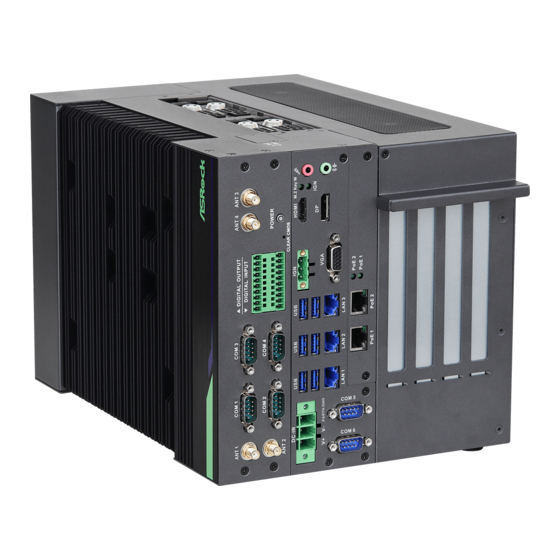
/ iEPF-9012S-EY4 / iEP-9010E / iEP-9012E / iEPF-9020S-EY4 / iEPF-9022S-EY4 / iEP-9020E / iEP-9022E Chapter 2 System Overview This chapter provides diagrams showing the location of important components of the system system. 2.1 System Front Panel 10 11 Description... - Page 43 Remote Power On/Off Switch (IGN) 2 x USB 3.2 Gen2x1 Ports (R680E sku) 2 x USB 2.0 Ports (H610 sku) VGA Port PoE1 Port Status LED (PoE 1) PoE2 Port Status LED (PoE 2) LAN RJ-45 PoE Port (PoE 2) LAN RJ-45 Port (LAN 3) (R680E sku) LAN RJ-45 PoE Port (PoE 1) LAN RJ-45 Port (LAN 2)
-
Page 44: Control Panel Buttons And Led Indicators
/ iEPF-9012S-EY4 / iEP-9010E / iEP-9012E / iEPF-9020S-EY4 / iEPF-9022S-EY4 / iEP-9020E / iEP-9022E 2.1.1 Control Panel Buttons and LED Indicators Power Switch Press the power switch button to toggle the system power-on and power-off modes. To remove all power from the system completely, disconnect the power cord from the system. - Page 45 PoE 2 Port Status LED Status Description Solid Green PoE 2 Port is connected to a PoE device No PoE connection M.2 Slot (Key M) Status LED Status Description Blinking Green M.2 Slot (Key M) on the motherboard is populated with a M.2 module.
-
Page 46: I/O Connectors
/ iEPF-9012S-EY4 / iEP-9010E / iEP-9012E / iEPF-9020S-EY4 / iEPF-9022S-EY4 / iEP-9020E / iEP-9022E 2.1.2 I/O Connectors Connector Description Antenna Port Connect the antenna cable to this connector. This system provides six COM ports through Serial Port (COM) D-sub 9-pin connectors. -
Page 47: Hdd Panel
2.2 HDD Panel iEPF-9010S Series / iEP-9010E Series / iEPF-9020S Series / iEP-9020E Series Description 2.5" HDD/SSD Tray (HDD0) 2.5" HDD/SSD Tray (HDD1) 2.5" HDD/SSD Tray (HDD3) 2.5" HDD/SSD Tray (HDD2) Side Vent 2 x SIM Card Slots (SIM1 is for M.2 B key slot) -
Page 48: Drive Tray Leds
/ iEPF-9012S-EY4 / iEP-9010E / iEP-9012E / iEPF-9020S-EY4 / iEPF-9022S-EY4 / iEP-9020E / iEP-9022E 2.3 Drive Tray LEDs Description HDD Power LED HDD Activity LED Status LED Definitions HDD Power LED Status Description Blue HDD powered-on No power to HDD... -
Page 49: Chapter 3 Hardware Installation And Maintenance
Chapter 3 Hardware Installation and Maintenance This chapter helps you disassemble the system and install components. Before You Begin Before you work with the system, pay close attention to the “Important Safety Instructions” at the beginning of this manual. 1. Make sure the system is powered off. Power down the system if it is still running. -
Page 50: How To Install The Hard Disk Drive
/ iEPF-9012S-EY4 / iEP-9010E / iEP-9012E / iEPF-9020S-EY4 / iEPF-9022S-EY4 / iEP-9020E / iEP-9022E 3.1 How to Install the Hard Disk Drive Installing a Hard Disk Drive into 2.5" Hard Drive Tray The system supports hot-swappable 2.5" hard drives. - Page 51 Installing a 2.5” Hard Drive to the Hard Drive Tray 1. Place a 2.5" HDD into the tray with the printed circuit board side facing down. Carefully align the mounting holes in the hard drive and the tray. 2. Secure the hard drive using four screws. 3.
-
Page 52: How To Install The Sim Card
/ iEPF-9012S-EY4 / iEP-9010E / iEP-9012E / iEPF-9020S-EY4 / iEPF-9022S-EY4 / iEP-9020E / iEP-9022E 3.2 How to Install the SIM Card Installing a SIM Card into a SIM Card Slot 1. Release the screw and remove the SIM card slot cover. - Page 53 2. Insert a SIM card to the SIM car slot. SIM1 (Upper Slot): When inserting the SIM Card to the upper slot, make sure the notch on the SIM card is oriented with the gold contacts face down. SIM2 (Lower Slot): When inserting the SIM Card to the lower slot, make sure the notch on the SIM card is oriented with the gold contacts face up.
-
Page 54: How To Disassemble The System
/ iEPF-9012S-EY4 / iEP-9010E / iEP-9012E / iEPF-9020S-EY4 / iEPF-9022S-EY4 / iEP-9020E / iEP-9022E 3.3 How to Disassemble the System 1. Release all screws on the heasink side 2. Remove the heatsink.. 3. Release the screws. 4. Remove the small panel from the I/O side of the system. - Page 55 5. Release the screws and remove the middle panel from the I/O side of the system. 6. Release the screws. 7. Remove the big panel from the I/O side of the system.
- Page 56 / iEPF-9012S-EY4 / iEP-9010E / iEP-9012E / iEPF-9020S-EY4 / iEPF-9022S-EY4 / iEP-9020E / iEP-9022E 8. Release the screw. 9. Push the cover toward the I/O side of the chassis to remove the cover from the locked position. Remove the cover.
- Page 57 11. Remove the screws from the inside of the chassis. 12. Remove the screws from the rear side of the chassis.
- Page 58 / iEPF-9012S-EY4 / iEP-9010E / iEP-9012E / iEPF-9020S-EY4 / iEPF-9022S-EY4 / iEP-9020E / iEP-9022E 13. Pull out the motherboard tray from the system.
-
Page 59: How To Install The Desk Mount Bracket
Series / iEP-9020E Series and secure them with eight screws. iEPF-9010S Series iEP-9010E Series iEPF-9020S Series iEP-9020E Series 2. Then you can attach the iEPF-9010S Series / iEPF-9020S Series or iEP-9010E Series / iEP-9020E Series to any horizontal surface. iEPF-9010S Series iEP-9010E Series iEPF-9020S Series... -
Page 60: How To Install The Rubber Foot
Series / iEP-9020E Series and secure them with four screws. iEPF-9010S Series iEP-9010E Series iEPF-9020S Series iEP-9020E Series 2. Then you can put the iEPF-9010S Series / iEPF-9020S Series or iEP-9010E Series / iEP- 9020E Series to any horizontal surface. iEPF-9010S Series iEP-9010E Series iEPF-9020S Series... -
Page 61: Chapter 4 Motherboard
Chapter 4 Motherboard 4.1 Motherboard Layout iEP(F)-9010 Series & iEP(F)-9020 Series Top Side PWR_BAT1 CLRMOS1 CLRMOS2 SIO_AT1 SMBUS_TEST1 ATX12V1 DC_IN1 BUZZ1 PCIE2 PCIE1 USB 3.2 Gen2 Top: T: USB3_1 LAN1 B: USB3_2 SATA_CON1 CMOS Battery USB 3.2 Gen2 Top: T: USB3_3 LAN2 B: USB3_4 PANEL1... - Page 62 / iEPF-9012S-EY4 / iEP-9010E / iEP-9012E / iEPF-9020S-EY4 / iEPF-9022S-EY4 / iEP-9020E / iEP-9022E Rear Side...
- Page 63 1 : M.2 Key-B Socket (M2_B1) 2 : SMBUS_TEST1 3 : PWR_BAT1 4 : SATA Connector (SATA_CON1) 5 : Clear CMOS Headers (CLRMOS1, CLRMOS2) 6 : M.2 Key-E Socket (M2_E1) 7 : ATX/AT Mode Jumper (SIO_AT1) 8 : Chassis Intrusion Headers (CI1, CI2) 9 : M.2 Key-M Socket (M2_M1) 10 : DC Input Connector (DC_IN1) 11 : Top : RJ45 LAN Port (LAN1) (Supports vPro)
- Page 64 / iEPF-9012S-EY4 / iEP-9010E / iEP-9012E / iEPF-9020S-EY4 / iEPF-9022S-EY4 / iEP-9020E / iEP-9022E iEP(F)-9012 Series & iEP(F)-9022 Series Top Side PWR_BAT1 CLRMOS1 CLRMOS2 SIO_AT1 SMBUS_TEST1 ATX12V1 DC_IN1 BUZZ1 PCIE2 PCIE1 USB 3.2 Gen2 Top: T: USB3_2 LAN1 B: USB3_1...
- Page 65 Rear Side DDR4_B1 DDR4_A1 SIM1...
- Page 66 / iEPF-9012S-EY4 / iEP-9010E / iEP-9012E / iEPF-9020S-EY4 / iEPF-9022S-EY4 / iEP-9020E / iEP-9022E 1 : M.2 Key-B Socket (M2_B1) 2 : SMBUS_TEST1 3 : PWR_BAT1 4 : SATA Connector (SATA_CON1) 5 : Clear CMOS Headers (CLRMOS1, CLRMOS2) 6 : M.2 Key-E Socket (M2_E1)
-
Page 67: Jumpers Setup
4.2 Jumpers Setup iEP(F)-9010 Series / iEP(F)-9020 Series / iEP(F)-9012 Series / iEP(F)-9022 Series PWR_BAT1 Open : Normal Short : Charge Battery (2-pin PWR_BAT1) (see pp. 52, 55, No. 3) Clear CMOS Jumpers CLRMOS1 : 1-2 : Normal (3-pin CLRMOS1) (see pp. - Page 68 / iEPF-9012S-EY4 / iEP-9010E / iEP-9012E / iEPF-9020S-EY4 / iEPF-9022S-EY4 / iEP-9020E / iEP-9022E Chassis Intrusion Headers This motherboard supports CASE OPEN detection feature that detects if the chas- (2-pin CI1, CI2) (see pp. 52, 55, No. 8) sis cover has been removed. This feature...
-
Page 69: Onboard Headers And Connectors
4.3 Onboard Headers and Connectors iEP(F)-9010 Series / iEP(F)-9020 Series / iEP(F)-9012 Series / iEP(F)-9022 Series SMBUS_TEST1 4-pin SMBUS_TEST1) (see pp. 52, 55, No. 2) Signal Name Signal Name Signal Name Signal Name SMBUS_TEST SMB_CLK SMB_DATA SATA Connector Signal Name Signal Name SATA_CON1 (SATA_CON1) - Page 70 / iEPF-9012S-EY4 / iEP-9010E / iEP-9012E / iEPF-9020S-EY4 / iEPF-9022S-EY4 / iEP-9020E / iEP-9022E POE Power Connector (4-pin PWR_POE1) (see p. 52, No. 16; p. 55, No. 15) Signal Name Signal Name Signal Name Signal Name +12V +12V +3VSB...
- Page 71 COM Port Headers Signal Signal Name Name (9-pin COM5, 6) RRXD DDCD# (see p. 52 No. 23; p. 55, No. 22) DDTR# TTXD DDSR# CCTS# RRTS# This motherboard supports RS232/422/485 on COM5, 6 ports. Please refer to the table below for the pin definition.
- Page 72 / iEPF-9012S-EY4 / iEP-9010E / iEP-9012E / iEPF-9020S-EY4 / iEPF-9022S-EY4 / iEP-9020E / iEP-9022E PLED (System Power LED): Connect to the power status indicator on the chassis front panel. The LED is on when the system is operating. The LED keeps blinking when the sys-tem is in S1 sleep state. The LED is off when the system is in S3/S4 sleep state or powered off (S5).
- Page 73 4-Pin 12V ATX Power Connector (4-pin ATX12V1) 1-2 : GND (see p. 52, No. 29; p. 55, No. 28) 3-4 : DC Input Please connect a DC +12V~28V power supply to this connector.
-
Page 74: Expansion Slots
/ iEPF-9012S-EY4 / iEP-9010E / iEP-9012E / iEPF-9020S-EY4 / iEPF-9022S-EY4 / iEP-9020E / iEP-9022E 4.4 Expansion Slots PCIE1 PCIE2 Signal Name Signal Name Signal Name Signal Name +12V +12V +12V +12V +12V +12V +12V +12V +12V +12V X16_CLKREQ#_R PCH_ECLK_X8... - Page 75 M.2 Key-E Socket (M.2_E1) M.2 Key-B Socket (M.2_B1) Signal Name Signal Name Signal Name Signal Name +3VSB +3.3V +3VSB USB_D+ +3.3V USB_D- +3.3V CNV_RF_RESET CNV_WGR_D1- CNV_WGR_D1+ MODEM_CLKREQ CNV_WGR_D0- CNV_WGR_D0+ CNV_BRI_RSP CNV_WGR_CLK- WAKE# PEFCLKp CNV_WGR_CLK+ PEFCLKn CLKREQ# PERST# CNV_BGI_DT PETP0 CNV_RGI_RSP PETp PETn0 CNV_BRI_DT...
-
Page 76: Chapter 5 Uefi Setup Utility
Chapter 5 UEFI Setup Utility 5.1 Introduction ASRock Industrial UEFI (Unified Extensible Firmware Interface) is a BIOS utility which offers tweak-friendly options in an advanced viewing interface. The UEFI system works with a USB mouse and offers users a faster, sleeker experience. - Page 77 5.1.2 UEFI Menu Bar The top of the screen has a menu bar with the following selections: Main For setting system time/date information Advanced For advanced system configurations H/W Monitor Displays current hardware status Security For security settings Boot For configuring boot settings and boot priority Exit Exit the current screen or the UEFI Setup Utility Because the UEFI software is constantly being updated, the following UEFI setup...
- Page 78 / iEPF-9012S-EY4 / iEP-9010E / iEP-9012E / iEPF-9020S-EY4 / iEPF-9022S-EY4 / iEP-9020E / iEP-9022E 5.1.3 Navigation Keys Use < > key or < > key to choose among the selections on the menu bar, and use < > key or <...
-
Page 79: Main Screen
5.2 Main Screen When you enter the UEFI SETUP UTILITY, the Main screen will appear and display the system overview. iEP-9010E iEP-9020E Because the UEFI software is constantly being updated, the following UEFI setup screens and descriptions are for reference purpose only, and they may not exactly match what you see on your screen. -
Page 80: Advanced Screen
/ iEPF-9012S-EY4 / iEP-9010E / iEP-9012E / iEPF-9020S-EY4 / iEPF-9022S-EY4 / iEP-9020E / iEP-9022E 5.3 Advanced Screen In this section, you may set the configurations for the following items: CPU Con- figuration, Chipset Configuration, Intel(R) Time Coordinated Computing, Storage Configuration, Super IO Configuration, ACPI Configuration, USB Configuration and Trusted Computing. -
Page 81: Cpu Configuration
5.3.1 CPU Configuration Intel Hyper Threading Technology Intel Hyper Threading Technology allows multiple threads to run on each core, so that the overall performance on threaded software is improved. Configuration options: [Enabled] [Disabled] Active Processor P-Cores This allows you to select the number of cores to enable in each processor package. Active Processor E-Cores This allows you to select the number of E-Cores to enable in each processor package. - Page 82 / iEPF-9012S-EY4 / iEP-9010E / iEP-9012E / iEPF-9020S-EY4 / iEPF-9022S-EY4 / iEP-9020E / iEP-9022E Intel SpeedStep Technology Intel SpeedStep technology allows processors to switch between multiple frequen- cies and voltage points for better power saving and heat dissipation. CPU turbo ratio can be fixed when Intel SpeedStep Technology is set to [Disabled] and Intel Turbo Boost Technology is set to [Enabled].
-
Page 83: Chipset Configuration
5.3.2 Chipset Configuration Primary Graphics Adapter The option allows you to select a primary VGA. Configuration options: [Onboard] [PCI Express] (Options vary when you have installed a graphics card on your motherboard.) Above 4G Decoding The option allows you to enable or disable above 4G Memory Mapped IO decoding. This is disabled automatically when Aperture Size is set to 2048MB. - Page 84 / iEPF-9012S-EY4 / iEP-9010E / iEP-9012E / iEPF-9020S-EY4 / iEPF-9022S-EY4 / iEP-9020E / iEP-9022E Share Memory Share memory allows you to configure the size of memory that is allocated to the integrated graphics processor when the system boots up.
-
Page 85: Intel(R) Time Coordinated Computing
5.3.3 Intel(R) Time Coordinated Computing #AC Split Lock Enable or Disable Alignment Check Exception (#AC). When enabled, this will assert an #AC when any atomic operation has an operand that crisses two cache lines. #GP Split Lock Enable or Disable GP Fault Exception (GP#). When enabled, this will assert an GP# when encountering a Lock to un-cacheable memory before the bus is locked. - Page 86 / iEPF-9012S-EY4 / iEP-9010E / iEP-9012E / iEPF-9020S-EY4 / iEPF-9022S-EY4 / iEP-9020E / iEP-9022E Inte(R) TCC Authentication Menu Press Enter to configure Intel(R) TCC Authentication Menu options. Intel(R) TCC Mode Enable or Disable Intel(R) TCC Mode. When enabled, this will modify system settings to improve real-time performance.
-
Page 87: Storage Configuration
5.3.4 Storage Configuration SATA Controller(s) The option allows you to enable or disable the SATA controllers. Configuration options: [Enabled] [Disabled] SATA Mode Selection AHCI supports new features that improve performance. Configuration option: [AHCI] AHCI (Advanced Host Controller Interface) supports NCQ and other new features that will improve SATA disk performance but IDE mode does not have these advantages. - Page 88 / iEPF-9012S-EY4 / iEP-9010E / iEP-9012E / iEPF-9020S-EY4 / iEPF-9022S-EY4 / iEP-9020E / iEP-9022E Hard Disk S.M.A.R.T. S.M.A.R.T stands for Self-Monitoring, Analysis, and Reporting Technology. It is a monitoring system for computer hard disk drives to detect and report on various indicators of reliability.
-
Page 89: Super Io Configuration
5.3.5 Super IO Configuration COM1 Configuration Use this to set parameters of COM1. Type Select Use this to select COM1 port type: [RS232], [RS422] or [RS485]. COM2 Configuration Use this to set parameters of COM2. Type Select Use this to select COM2 port type: [RS232], [RS422] or [RS485]. COM3 Configuration Use this to set parameters of COM3. - Page 90 / iEPF-9012S-EY4 / iEP-9010E / iEP-9012E / iEPF-9020S-EY4 / iEPF-9022S-EY4 / iEP-9020E / iEP-9022E Type Select Use this to select COM6 port type: [RS232], [RS422] or [RS485]. WDT Timeout Reset Use this to set the Watch Dog Timer. DID0 Type Select Use this to set DIO Type: [Input].
- Page 91 DID12 Type Select Use this to set DIO Type: [Output Low] or [Output High]. DID13 Type Select Use this to set DIO Type: [Output Low] or [Output High]. DID14 Type Select Use this to set DIO Type: [Output Low] or [Output High]. DID15 Type Select Use this to set DIO Type: [Output Low] or [Output High].
-
Page 92: Acpi Configuration
/ iEPF-9012S-EY4 / iEP-9010E / iEP-9012E / iEPF-9020S-EY4 / iEPF-9022S-EY4 / iEP-9020E / iEP-9022E 5.3.6 ACPI Configuration Suspend to RAM Suspend to RAM allows you to select [Disabled] for ACPI suspend type S1. It is recommended to select [Auto] for ACPI S3 power saving. -
Page 93: Usb Configuration
5.3.7 USB Configuration USB Power Control Use this option to control USB power. M.2 Key_B Function The item enables or disables M.2 Key_B USB function. -
Page 94: Trusted Computing
/ iEPF-9012S-EY4 / iEP-9010E / iEP-9012E / iEPF-9020S-EY4 / iEPF-9022S-EY4 / iEP-9020E / iEP-9022E 5.3.8 Trusted Computing Security Device Support Security Device Support allows you to enable or disable BIOS support for security device. O.S. will not show Security Device. TCG EFI protocol and INT1A interface will not be available. - Page 95 Configuration options: [Enabled] [Disabled] Endorsement Hierarchy This item allows you to enable or disable Endorsement Hierarchy. Configuration options: [Enabled] [Disabled] Physical Presence Spec Version Select this item to tell OS to support PPI spec version 1.2 or 1.3. Please note that some HCK tests might not support version 1.3.
-
Page 96: Hardware Health Event Monitoring Screen
/ iEPF-9012S-EY4 / iEP-9010E / iEP-9012E / iEPF-9020S-EY4 / iEPF-9022S-EY4 / iEP-9020E / iEP-9022E 5.4 Hardware Health Event Monitoring Screen This section allows you to monitor the status of the hardware on your system, including the parameters of the CPU temperature, motherboard temperature, CPU fan speed, chassis fan speed, and the critical voltage. -
Page 97: Security Screen
5.5 Security Screen In this section, you may set, change or clear the supervisor/user password for the system. Supervisor Password Set or change the password for the administrator account. Only the administrator has the authority to change the settings in the UEFI Setup Utility. Leave it blank and press enter to remove the password. -
Page 98: Boot Screen
/ iEPF-9012S-EY4 / iEP-9010E / iEP-9012E / iEPF-9020S-EY4 / iEPF-9022S-EY4 / iEP-9020E / iEP-9022E 5.6 Boot Screen This section displays the available devices on your system for you to configure the boot settings and the boot priority. Boot Option #1 The item allows you to set the system boot order. -
Page 99: Exit Screen
5.7 Exit Screen Save Changes and Exit When you select this option, the following message “Save configuration changes and exit setup?” will pop out. Select [Yes] to save the changes and exit the UEFI SETUP UTILITY. Discard Changes and Exit When you select this option, the following message “Discard changes and exit setup?”...
Need help?
Do you have a question about the iEP-9010E and is the answer not in the manual?
Questions and answers