
Subscribe to Our Youtube Channel
Related Manuals for ASRock Industrial IMB-1005


Summary of Contents for ASRock Industrial IMB-1005
- Page 1 IMB-1005 User Manual Version 1.0 Published July 24, 2023 Copyright©2023 ASRockInd INC. All rights reserved.
- Page 2 Version 1.0 Published July, 2023 Copyright©2023 ASRockInd INC. All rights reserved. Copyright Notice: No part of this documentation may be reproduced, transcribed, transmitted, or translated in any language, in any form or by any means, except duplication of documentation by the purchaser for backup purpose, without written consent of ASRockInd Inc.
- Page 3 WARNING THIS PRODUCT CONTAINS A BUTTON BATTERY If swallowed, a button battery can cause serious injury or death. Please keep batteries out of sight or reach of children. CALIFORNIA, USA ONLY The Lithium battery adopted on this motherboard contains Perchlorate, a toxic substance controlled in Perchlorate Best Management Practices (BMP) regulations passed by the California Legislature.
-
Page 4: Table Of Contents
Contents Chapter 1 Introduction Package Contents Specifications Motherboard Layout I/O Panel Block Diagram Chapter 2 Installation Screw Holes Pre-installation Precautions Installation of Memory Modules Expansion Slots Jumpers Setup Onboard Headers and Connectors Chapter 3 UEFI SETUP UTILITY Introduction 3.1.1 Entering BIOS Setup 3.1.2 UEFI Menu Bar 3.1.3... - Page 5 3.3.4 Super IO Configuration 3.3.5 ACPI Configuration 3.3.6 USB Configuration 3.3.7 Trusted Computing Hardware Health Event Monitoring Screen Security Screen Boot Screen Exit Screen...
-
Page 6: Chapter 1 Introduction
If you require technical support related to this motherboard, please visit our website for specific information about the model you are using. https://www.asrockind.com/support/index.asp 1.1 Package Contents ASRockInd IMB-1005 Motherboard (Mini-ITX (6.7-in x 6.7-in x 1.6-in, 17.0 cm x 17.0 cm x 4.1 cm) -
Page 7: Specifications
1.2 Specifications Mini-ITX (6.7-in x 6.7-in x 1.6-in, 17.0 cm x 17.0 cm x 4.1 Form Factor Dimensions Intel® Alder Lake-N SoC Processors IMB-1005J (N97, QC, Max Speed Up to 3.6GHz, 12W) Processor *For other CPU SKUs request, please contact regional Sales System for availability Chipset... - Page 8 IMB-1005 2 x USB 3.2 Gen1 (1 x USB 3.2 header) 3 x USB 2.0 (1 x 2.54 pitch header, 1 x USB 2.0 Type-A vertical connector) COM4 (RS-232) COM5 (RS-232 or TTL (optional)) COM6 (RS-232 or ccTalk (optional)) Internal...
-
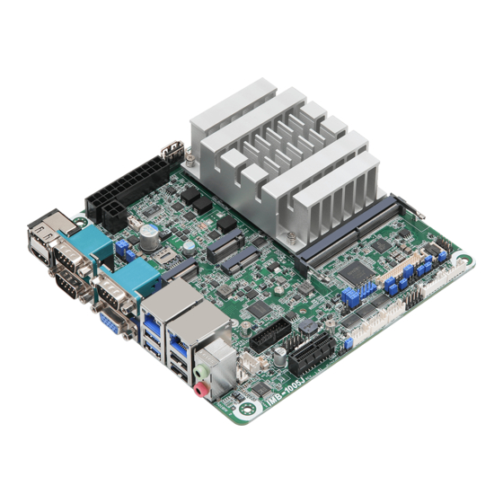
Page 9: Motherboard Layout
B: USB2_3 USB3H1 3 4 HD_AUDIO1 SPEAKER1 PWR_COM4 PWR_COM5 USB2_5_6 PWR_COM6 BAT1 LVDS1 PLED PWRBTN BUZZ2 BIOS PANEL1 HDLED RESET PNL_PWR1 BKT_PWR1 JGPIO_PWR1 SPDIF1 TPM1 JGPIO_SET1 CLRMOS1 CLRMOS2 BLT_PWM1 BLT_PWM2 SIO_AT1 PCIE1 COM4 COM5 COM6 DACC1 IMB-1005 CC_TALK_OUT1 JGPIO1 BLT_VOL1 BLT_PWR1... - Page 10 IMB-1005 Back: MIPI1 ESPI1...
- Page 11 1 : COM Port PWR Setting Jumpers PWR_COM1 (For COM Port1) PWR_COM2 (For COM Port2) PWR_COM3 (For COM Port3) 2 : 4-pin Power Connector (ATX12V1) 3 : 24-pin ATX Power Input Connector (ATXPWR1) 4 : USB 2.0 Port (USB2_7) 5 : SMBUS_TEST1 6 : 4-Pin CPU FAN Connector (+12V) (CPU_FAN1) 7 : SATA Power Output Connector (SATA_PWR1) 8 : SATA3 Connector (SATA3_0)
- Page 12 IMB-1005 35 : Battery Connector (BAT1) 36 : 3W Audio AMP Output Wafer (SPEAKER1) 37 : Front Panel Audio Header (HD_AUDIO1) Back Side: 38 : ESPI Header (ESPI1) 39 : MIPI1 Socket (MIPI1 (optional))
-
Page 13: I/O Panel
1.4 I/O Panel HDMI Port (HDMI2) Audio Output : Pink – Mic In COM Port (COM1) (RS232/422/485)* USB 2.0 Ports (USB2_3_4) COM Port (COM3) (RS232/422/485)* USB 3.2 Gen1 Ports (USB3H_1_2) RJ45 LAN Port (LAN1)** 10 D-Sub Port (VGA1) RJ45 LAN Port (LAN2)** 11 COM Port (COM2) (RS232/422/485)* Audio Output : Green –... -
Page 14: Block Diagram
IMB-1005 1.5 Block Diagram IMB-1005J SO-DIMM LVDS/eDP Chrontel LVDS/eDP Channel A DDR4 By pass mode CH7513 HDMI PCIe Gen3 x1 HDMI PCIe x1 slot Connector IT66318 HDMI SATA x1 HDMI SATA Port Connector IT66318 PCIe Gen3 x1 Realtek CNVi M.2 Key E... -
Page 15: Chapter 2 Installation
Chapter 2 Installation This is a Mini-ITX (6.7-in x 6.7-in x 1.6-in, 17.0 cm x 17.0 cm x 4.1 cm) form factor motherboard. Before you install the motherboard, study the configuration of your chassis to ensure that the motherboard fits into it. Make sure to unplug the power cord before installing or removing the motherboard. -
Page 16: Installation Of Memory Modules
IMB-1005 2.3 Installation of Memory Modules IMB-1005 provides one 260-pin DDR4 (Double Data Rate 4) SO-DIMM slots, and supports Single Channel Memory Technology. Please make sure to disconnect the power supply before adding or removing SO- DIMMs or the system components. -
Page 17: Expansion Slots
2.4 Expansion Slots There are 1 PCI Express Gen3 slot, 3 M.2 sockets and 1 SIM socket on this motherboard. PCIE slot: PCIE1 (PCIe x1 slot) is used for PCIe Gen3 x1 lane width card. M.2 sockets: 1 x M.2 (Key E, 2230) with PCIe x1, USB 2.0 and CNVi for Wireless 1 x M.2 (Key B, 3042/3052) with PCIe x1, USB 3.2 Gen1, USB 2.0 and SIM for 4G/5G 1 x M.2 (Key M, 2242/2260/2280) with PCIe Gen3 x1 or SATA3 for SSD... -
Page 18: Jumpers Setup
IMB-1005 2.5 Jumpers Setup The illustration shows how jumpers are setup. When the jumper cap is placed on pins, the jumper is “Short.” If no jumper cap is placed on pins, the jumper is “Open. ” The illustration shows a 3-pin jumper whose pin1 and pin2 are “Short”... - Page 19 Chassis Intrusion Headers Setting Description (2-pin CI1, CI2) Close Active Case Open (see p. 4, No. 18) Open Normal (Default) Setting Description Close Normal (Default) Open Active Case Open This motherboard supports CASE OPEN detection feature that detects if the chassis cover has been removed.
- Page 20 IMB-1005 Note: CLRMOS1 allows you to clear the data in CMOS. To clear and reset the system param- eters to default setup, please turn off the computer and unplug the power cord from the power supply. After waiting for 15 seconds, use a jumper cap to short pin 2 and pin 3 on CLRMOS1 for 5 seconds.
- Page 21 DACC Jumper Setting Description Disable Auto Clear (2-pin DACC1) Open (see p. 4, No. 30) CMOS Enable Auto Clear Short CMOS (Default) *Auto clear CMOS when system boot improperly.
-
Page 22: Onboard Headers And Connectors
IMB-1005 2.6 Onboard Headers and Connectors Onboard headers and connectors are NOT jumpers. Do NOT place jumper caps over these headers and connectors. Placing jumper caps over the headers and connectors will cause per- manent damage to the motherboard! 4-pin Power Connector... - Page 23 SMBUS_TEST1 Signal Name GPIO (4-pin SMBUS_TEST1) SMB_CLK (see p. 4, No. 5) SMB_DATA CPU Fan Connector (+12V) Signal Name (4-pin CPU_FAN1) +12V (see p. 4, No. 6) CPU_FAN_SPEED FAN_SPEED_CONTROL The board offers three 4-pin CPU fan (Smart Fan) connectors which are compatible with 3-pin CPU fan.
- Page 24 IMB-1005 LVDS Panel Connector (40-pin LVDS1) * eDP pin definition (switch by BIOS): (see p. 4, No. 14) Signal Name Signal Name Signal Name Signal Name LCD_VCC LCD_VCC LCD_VCC LCD_VCC +3.3V LVDS_A_DATA0# LVDS_A_DATA0 EDP_TX1# EDP_TX1 LVDS_A_DATA1# LVDS_A_DATA1 EDP_TX0# LVDS_A_DATA2# EDP_TX0...
- Page 25 Digital Input/Output Pin Header Signal Name Signal Name SIO_GP34 GPP_B15 (10-pin JGPIO1) SIO_GP35 GPP_E1 (see p. 4, No. 25) SIO_GP36 GPP_E2 SIO_GP37 GPP_E13 JGPIO_PWR Internal COM Port Headers (RS232) Signal Name Signal Name DDCD#1 RRXD (9-pin COM4~6) TTXD DDTR# (see p. 4, No. 27) DDSR# RRTS# CCTS#...
- Page 26 IMB-1005 System Panel Header Signal Name Signal Name HDLED+ PLED+ (9-pin PANEL1) HDLED- PLED- PWRBTN# (see p. 4, No. 33) RESET# This header accommodates several system front panel functions. Connect the power switch, reset switch and system status indicator on the chassis to this header according to the pin assignments below.
- Page 27 3W Audio AMP Output Wafer Signal Name OUTLN (4-pin SPEAKER1) OUTLP (see p. 4, No. 36) OUTRP OUTRN Front Panel Audio Header Signal Name Signal Name MIC2_L (8-pin HD_AUDIO1) MIC2_R OUT2_R MIC_RET (see p. 4, No. 37) J_SENSE OUT2_L OUT_RET This is line out/microphone interface for front panel audio cable that allows jack detection, convenient connection and control of audio devices.
- Page 28 IMB-1005 MIPI1 Socket Signal Name (36-pin MIPI1) CSI_B_DN2 (see p. 5, No. 39) CSI_B_DP2 CSI_B_DN1 CSI_B_DP1 CSI_B_CLK_N CSI_B_CLK_P CSI_B_DN0 CSI_B_DP0 CSI_B_DN3 CSI_B_DP3 +2.8V +2.8V +1.8V +1.2V IMBCLKOUT0 I2C1_SCL I2C1_SDA BUF_PLT_RST_1.8_R_N +1.2V GPP_S1 GPP_S2 GPP_S3...
-
Page 29: Chapter 3 Uefi Setup Utility
Chapter 3 UEFI SETUP UTILITY 3.1 Introduction ASRock Industrial UEFI (Unified Extensible Firmware Interface) is a BIOS utility which offers tweak-friendly options in an advanced viewing interface. The UEFI system works with a USB mouse and offers users a faster, sleeker experience. -
Page 30: Uefi Menu Bar
IMB-1005 3.1.2 UEFI Menu Bar The top of the screen has a menu bar with the following selections: Main For setting system time/date information For advanced system configurations Advanced H/W Monitor Displays current hardware status Security For security settings Boot... -
Page 31: Navigation Keys
3.1.3 Navigation Keys Use < > key or < > key to choose among the selections on the menu bar, and use < > key or < > key to move the cursor up or down to select items, then press <Enter>... -
Page 32: Main Screen
IMB-1005 3.2 Main Screen When you enter the UEFI SETUP UTILITY, the Main screen will appear and display the system overview. Because the UEFI software is constantly being updated, the following UEFI setup screens and descriptions are for reference purpose only, and they may not exactly match what you see on your screen. -
Page 33: Advanced Screen
3.3 Advanced Screen In this section, you may set the configurations for the following items: CPU Configuration, Chipset Configuration, Storage Configuration, Super IO Configura- tion, ACPI Configuration, USB Configuration, and Trusted Computing. Setting wrong values in this section may cause the system to malfunction. Instant Flash Instant Flash is a UEFI flash utility embedded in Flash ROM. -
Page 34: Cpu Configuration
IMB-1005 3.3.1 CPU Configuration Active Processor E-Cores This allows you to select the number of E-Cores to enable in each processor package. NOTE: Number of P-Cores and E-Cores are looked at together. When both are {0,0}, Pcode will enable all cores. - Page 35 CFG Lock The option allows you to enable or disable the CFG Lock. Configuration options: [Enabled] [Disabled] Intel Virtualization Technology Intel Virtualization Technology allows a platform to run multiple operating systems and applications in independent partitions, so that one computer system can function as multiple virtual systems.
- Page 36 IMB-1005 Power Limit 1 "Power Limit 1 in Mi l li Watts. BIOS w i l l round to t he nearest 1/8W when programming. 0 = no custom override. For 12.50W, enter 12500. Overclocking SKU: Value must be between Max and Min Power Limits (specified by PACKAGE_ POWER_SKU_MSR).
-
Page 37: Chipset Configuration
3.3.2 Chipset Configuration VT-d Intel® Virtualization Technology for Directed I/O helps your virtual machine monitor better utilize hardware by improving application compatibility and reliability, and providing additional levels of manageability, security, isolation, and I/O performance. Configuration options: [Enabled] [Disabled] Re-Size BAR Support If system has Resizable BAR capable PCIe Devices, this option enables or disables Resizable BAR Support. - Page 38 IMB-1005 Render Standby Power down the render unit when the GPU is idle for lower power consumption. Active LVDS Use this to enable or disable the LVDS. The default value is [Disabled]. Set the item to [Enabled]. Then press <F10> to save the setting and restart the system. Now the default value of Active LVDS is changed to [Enabled] (F9 load default is also set to [Enabled]).
-
Page 39: Storage Configuration
3.3.3 Storage Configuration SATA Controller(s) The option allows you to enable or disable the SATA controllers. Configuration options: [Enabled] [Disabled] SATA Mode Selection AHCI supports new features that improve performance. Configuration option: [AHCI] Hybrid Storage Detection and Configuration Mode The option allows you to select Hybrid Storage Detection and Configuration Mode. Configuration options: [Dynamic Configuration for Hybrid Storage Enable] [Disabled] SATA Aggressive Link Power Management... - Page 40 IMB-1005 Hard Disk S.M.A.R.T. S.M.A.R.T stands for Self-Monitoring, Analysis, and Reporting Technology. It is a monitoring system for computer hard disk drives to detect and report on various indicators of reliability. Configuration options: [Enabled] [Disabled]...
-
Page 41: Super Io Configuration
3.3.4 Super IO Configuration COM1 Configuration Use this to set parameters of COM1. Type Select Use this to select COM1 port type: [RS232], [RS422] or [RS485]. COM2 Configuration Use this to set parameters of COM2. Type Select Use this to select COM2 port type: [RS232], [RS422] or [RS485]. COM3 Configuration Use this to set parameters of COM3. - Page 42 IMB-1005 COM5 Configuration Use this to set parameters of COM5. COM6 Configuration Use this to set parameters of COM6. WDT Timeout Reset Use this to set the Watch Dog Timer.
-
Page 43: Acpi Configuration
3.3.5 ACPI Configuration Suspend to RAM Suspend to RAM allows you to select [Disabled] for ACPI suspend type S1. It is recommended to select [Auto] for ACPI S3 power saving. Configuration options: [Auto] [Disabled] PCIE Devices Power On Use this item to enable or disable PCIE devices to turn on the system from the power-soft-off mode. -
Page 44: Usb Configuration
IMB-1005 3.3.6 USB Configuration USB Power Control Use this option to control USB power. M.2 Key_B USB Function Enable or disable M.2 Key-B USB function. -
Page 45: Trusted Computing
3.3.7 Trusted Computing NOTE: Options vary depending on the version of your connected TPM module. Security Device Support Security Device Support allows you to enable or disable BIOS support for security device. O.S. will not show Security Device. TCG EFI protocol and INT1A interface will not be available. - Page 46 IMB-1005 SM3_256 PCR Bank SM3_256 PCR Bank allows you to enable or disable SM3_256 PCR Bank. Configuration options: [Enabled] [Disabled] Pending Operation Pending Operation allows you to schedule an Operation for the Security Device. NOTE: Your computer will reboot during restart in order to change State of the Device.
-
Page 47: Hardware Health Event Monitoring Screen
3.4 Hardware Health Event Monitoring Screen This section allows you to monitor the status of the hardware on your system, including the parameters of the CPU temperature, motherboard temperature, CPU fan speed, and the critical voltage. NOTE: Options vary depending on the features of your motherboard. CPU_Fan 1 Setting This item allows you to select a fan mode for CPU Fan 1. -
Page 48: Security Screen
IMB-1005 3.5 Security Screen In this section you may set or change the supervisor/user password for the system. You may also clear the user password. Supervisor Password Set or change the password for the administrator account. Only the administrator has the authority to change the settings in the UEFI Setup Utility. Leave it blank and press enter to remove the password. -
Page 49: Boot Screen
3.6 Boot Screen This section displays the available devices on your system for you to configure the boot settings and the boot priority. Boot From Onboard LAN The item allows the system to be waked up by the onboard LAN. Configuration options: [Enabled] [Disabled] Setup Prompt Timeout The item allows you to... -
Page 50: Exit Screen
IMB-1005 3.7 Exit Screen Save Changes and Exit When you select this option, the following message “Save configuration changes and exit setup?” will pop out. Select [Yes] to save the changes and exit the UEFI SETUP UTILITY. Discard Changes and Exit When you select this option, the following message “Discard changes and exit...
Need help?
Do you have a question about the IMB-1005 and is the answer not in the manual?
Questions and answers