
Related Manuals for ASRock Industrial iEP-6010E Series


Summary of Contents for ASRock Industrial iEP-6010E Series
- Page 1 iEP-5000G Series iEP-6010E-Series User Manual Version 1.0 Published April 2022 User Manual...
-
Page 2: Copyright Notice
In no event shall ASRock Industrial, its directors, officers, employees, or agents be liable for any indirect, special, incidental, or consequential damages (including damages for loss of... -
Page 3: Important Safety Instructions
Important Safety Instructions For user safety, please read and follow all instructions, Warnings, Cautions, and Notes marked in this manual and on the associated device before handling/operating the device, to avoid injury or damage. Read these safety instructions carefully. Retain this user manual for future reference. Read the Specifications section of this manual for detailed information on the recommended operating environment. - Page 4 AAAN3 is suitable for usage at TMA 40 °C (104 °F), and the output is rated 24Vdc, 13.75A, ES1.) If you need further assistance, contact ASRock Industrial for additional information. The terminal block is suitable for V+& V- for 14~28AWG. The torque value is 3.5 +/- 0.5kgf-cm.
-
Page 5: Replaceable Batteries
Replaceable batteries CAUTION : RISK OF EXPLOSION IF BATTERY IS REPLACED BY AN INCORRECT TYPE. DISPOSE OF USED BATTERIES ACCORDING TO THE INSTRUCTIONS BURN HAZARD Hot surface! Do not touch! Touching this surface could result in bodily injury. To reduce risk, allow the surface to cool before touching. -
Page 6: Contact Information
HDMI Licensing LLC in the United States and other countries. Contact Information If you need to contact ASRock Industrial or want to know more about ASRock Industrial, you’re welcome to visit ASRock Industrial’s website at www.asrockind.com; or you may contact your dealer for further information. -
Page 7: Table Of Contents
Contents Chapter 1 Introduction Package Contents Order Information Optional Items Product Specifications Block Diagram Chapter 2 Product Overview System Front Panel 2.1.1 System : Basic SKU (iEP-6010E-000/iEP-6011E-000/ iEP-6012E-000/iEP-6013E-000) 2.1.2 System : PoE/5G SKU (iEP-6010E-001/iEP-6012E-001/ iEP-6010E-003/iEP-6012E-003) System Top Panel 2.2.1 System : Basic SKU (iEP-6010E-000/iEP-6011E-000/ iEP-6012E-000/iEP-6013E-000) 2.2.2 System : PoE SKU (iEP-6010E-001/ iEP-6012E-001) - Page 8 Chapter 4 Carrier Board Carrier Board Layout_R1.01 Jumpers Setup_R1.01 Onboard Headers and Connectors_R1.01 Carrier Board Layout_R1.02 Jumpers Setup_R1.02 Onboard Headers and Connectors_R1.02 Expansion Slots (M.2 Sockets) Chapter 5 Flash the OS DSC-NV002-WT R1.01 DSC-NV002-WT R1.02 Chapter 6 iEP-6010E Series Setting Tool AsriTool...
- Page 9 iEP-601XE Series API Programming Guide (V1.3/2024.01.02) 6.2.1 setComVolt() 6.2.2 getComVolt() 6.2.3 setDB15Volt() 6.2.4 getDB15Volt() 6.2.5 setDIODirection() 6.2.6 setDOutValue() 6.2.7 getDIO() 6.2.8 setUartMode() 6.2.9 getUartMode() 6.2.10 saveConfigs () 6.2.11 loadConfigs () 6.2.12 defConfigs () 6.2.13 getVersion () iEP-601XE-Series 4G/5G User Guide 6.3.1 Activate 4G Module 6.3.2...
- Page 10 7.3.3 Driver Health Manager 7.3.4 Secure Boot Configuration 7.3.5 O/S Hardware Description Selection 7.3.6 iSCSI Configuration 7.3.7 NVIDIA Configuration 7.3.8 Network Device List Device Manager Boot Maintenance Manager...
-
Page 11: Chapter 1 Introduction
Series Chapter 1 Introduction Because the hardware specifications might be updated, the content of this documentation will be subject to change without notice. 1.1 Package Contents iEP-6010E Series • NVIDIA Jetson Orin NX SOM support, up to 100 SPARSE (50 DENSE) INT8 TOPS •... - Page 12 The iEP-6010E Series System Package Contents V+ V- No. Accessories Picture Description Black electric wire (-) M.2 Screw 2 (POE SKU) To fix M.2 module (PN:13G020773010AK) Red electric wire (+) 3 (BASIC/5G SKU) Terminal Block 3-pin phoenix type 1x3P ST 5.0m...
- Page 13 Series NYLOK Screw M3*9.5 Spare screws for BASIC SKU only. When shipment is BASIC SKU iEP- 601XE-000, X=0, 1, 2, or 3, NYLOK Screw M3*9.5 4 pieces will be left. NYLOK Screw M3*3.5 Spare screws for POE or 5G SKU only.
-
Page 14: Order Information
1.2 Order Information Model Name Description iEP-6010E-000 90PCA1E0-00000000 BASIC SKU with NVIDIA Jetson Orin NX 16GB SOM, w/o Storage, Mount, Adapter, WiFi, and w/o OS. iEP-6010E-001 90PCA1E0-01000000 POE SKU with NVIDIA Jetson Orin NX 16GB SOM, w/o Storage, Mount, Adapter, WiFi, and w/o OS. -
Page 15: Optional Items
CONN DIN RAIL Kit 13G020761000AI For securing the DIN RAIL bracket to the DIN RAIL WALL MOUNT 13G020760000AI Vertically mounting the iEP-6010E series on the Kit (Vertical) surface ADAPTER 04G266001001AI FSP 120W adaptor for Basic SKU 120W 19V W/O Connector... -
Page 16: Product Specifications
‧Carrier board reserved 2pcs Dual Lane MIPI-CSI2 connectors (Option for Mechanica DSC-NV002-WT R1.01), Carrier board reserved 2pcs Four Lane MIPI-CSI2 1.4 Product Specifications Dimensions connectors (Option for DSC-NV002-WT R1.02)** Indicator iEP-6010E Series SPECIFICATIONS Function Processor System Net Weight System on Module - NVIDIA Jetson Orin NX SOM 16GB support... - Page 17 (5G SKU Only, Orin NX SOM 16GB 5G SKU iEP-6010E-003, Orin Nano SOM 8GB 5G SKU iEP-6012E-003) iEP-6010E Series -For PCIe Gen3 x1 M.2 B Key 2280 SSD module (Option, Basic SKU Only) 1 x M.2 (Key E, 2230) for PCIe Gen3 x1 Wi-Fi and USB2.0 Bluetooth...
- Page 18 Storage Temperature -40°C~85°C ( -40°F~185°F) Humidity ~90% @ 45°C (non-condensing) CE, FCC Class A (EN61000-6-4/-2) *(e) Safety LVD*(e) Shock IEC 60068-2-27, Operating Shock 100G with 11 ms duration, V002 R1.01, half sine wave C-NV002 R1.02) Vibration IEC 60068-2-64, Operating Random Vibration 5 Grms, 5-500 Hz, E 802.3AF PoE 3 axes, 30 min/axis Add-on Feature / OS Support...
- Page 19 DSC-NV002-WT R1.01), Carrier board reserved 2pcs Four Lane MIPI-CSI2 iEP-6010E Series connectors (Option for DSC-NV002-WT R1.02)** Storage Temperat Humidity iEP-6010E Series_Developer Kit SPECIFICATIONS Add-on Featu Processor System Carrier board feat System on Module - NVIDIA Jetson Orin NX SOM 16GB support...
-
Page 20: Power Requirements
Power Requirements DC Input DC IN source: 12V~36V DC input, 80V Surge Protection. OVP , UVP , OCP , Reverse Protection, Phoenix type connector AC to DC Adaptor (Option) 120W Adapter, AC input 100-240Vac, 1.8A 50~60Hz, DC output 19V, 6.32A Storage Device M.2 Socket 1 x M.2 (Key M, 2280) for wide temperature PCIe Gen3 x 4... - Page 21 (Option for DSC-NV002-WT R1.01), Carrier board reserved 2pcs Four Lane MIPI-CSI2 connectors (Option for DSC-NV002-WT R1.02)** iEP-6010E Series OS Support NVIDIA JetPack 5.1.2 *(e) means estimation. **MIPI-CSI2 camera need to be turned off before system going to sleep mode. It is current NVIDIA JetPack limitation.
-
Page 22: Block Diagram
1.5 Block Diagram DSC-NV001-WT R1.01 (DSC-NV002-WT R1.01 for the orders before 2024/10/1.) PCIe Gen3 x1 USB3.2 Gen1 x1 M.2 KEY-B Micro SIM 3042/3052/2280 USB2.0 x1 USB2.0 x1 Micro USB Connector USB2.0 x1 Full UART 3in1 USB2.0 x1 Full COM COM2 USB2 to UART COM transceiver (RS-232/422/485) - Page 23 Series DSC-NV001-WT R1.02 (DSC-NV002-WT R1.02 for the orders after 2024/10/1.) PCIe Gen3 x1 USB3.2 Gen1 x1 M.2 KEY-B Micro SIM 3042/3052/2280 USB2.0 x1 USB2.0 x1 Micro USB Connector USB2.0 x1 Full UART 3in1 Full COM COM2 USB2.0 x1 USB2 to UART...
-
Page 24: Chapter 2 Product Overview
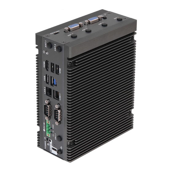
Chapter 2 Product Overview This chapter provides diagrams showing the location of important components of the iEP-6010E Series. 2.1 System Front Panel 2.1.1 System : Basic SKU (iEP-6010E-000/iEP-6011E-000/iEP-6012E-000/ iEP-6013E-000) - Page 25 Series Description Power Button: The power button allows you to turn the iEP-6010E Series on or off (Press Power Button for 10 seconds to shut down). Storage LED and DC IN LED: Storage LED indicator behaviors vary depending on the M.2 M Key storage module you use.
- Page 26 * This motherboard supports RS232/422/485 on COM2 port. Please refer to table below for the pin definition. In addition, COM2 port (RS232/422/485) can be adjusted in Chapter 6 iEP-6010E Series Setting Tool. You may refer to our user manual for details.
- Page 27 Series LAN ports**: The RJ-45 LAN ports support a standard Ethernet cable for 10/100/1000 Mbps connection to the local network. For the system equipped with DSC-NV002-WT R1.01: LAN1 port (SOM, 1G LAN): There are two LEDs on the LAN 1port. Please refer to the tables below for the LAN1 port LED indications.
-
Page 28: System : Poe/5G Sku (Iep-6010E-001/Iep-6012E-001/ Iep-6010E-003/Iep-6012E-003)
2.1.2 System : PoE/5G SKU (iEP-6010E-001/iEP-6012E-001/iEP-6010E-003/ iEP-6012E-003) - Page 29 Series Description Power Button: The power button allows you to turn the iEP-6010E Series on or off (Press Power Button for 10 seconds to shut down). Storage LED and DC IN LED: Storage LED indicator behaviors vary depending on the M.2 M Key storage module you use.
- Page 30 * This motherboard supports RS232/422/485 on COM2 port. Please refer to table below for the pin definition. In addition, COM2 port (RS232/422/485) can be adjusted in Chapter 6 iEP-6010E Series Setting Tool. You may refer to our user manual for details.
- Page 31 Series LAN ports**: The RJ-45 LAN ports support a standard Ethernet cable for 10/100/1000 Mbps connection to the local network. For the system equipped with DSC-NV002-WT R1.01: LAN1 port (SOM, 1G LAN): There are two LEDs on the LAN 1port. Please refer to the tables below for the LAN1 port LED indications.
-
Page 32: System Top Panel
2.2 System Top Panel 2.2.1 System : Basic SKU (iEP-6010E-000/iEP-6011E-000/iEP-6012E-000/ iEP-6013E-000) Description OS Flash: 1 x Micro USB 2.0 that supports Device mode only. It will be connected to a host computer to refresh the OS image. DPR: DPR connector is proprietary design of DIO, Power/GND, Remote Power Button signals and power/GND pins. -
Page 33: System : Poe Sku (Iep-6010E-001/ Iep-6012E-001)
Series 2.2.2 System : PoE SKU (iEP-6010E-001/ iEP-6012E-001) Description OS Flash: 1 x Micro USB 2.0 that supports Device mode only. It will be connected to a host computer to refresh the OS image. DPR: DPR connector is proprietary design of DIO, Power/GND, Remote Power Button signals and power/GND pins. - Page 34 POE or LAN ports*: 2x Intel I210AT ports, each port supports IEEE 802.3AF PoE when connecting with POE devices. It can be LAN ports to support a standard Ethernet cable for 10/100/1000 Mbps connection to local network. PoE1/LAN3 port: There are two LEDs on the PoE1/LAN3 port. Please refer to the tables below for the PoE1/LAN3 port LED indications.
-
Page 35: System : 5G Sku (Iep-6010E-003/Iep-6012E-003)
Series 2.2.3 System : 5G SKU (iEP-6010E-003/iEP-6012E-003) Description OS Flash: 1 x Micro USB 2.0 that supports Device mode only. It will be connected with a host computer to refresh the OS image. DPR: DPR connector is proprietary design of DIO, Power/GND, Remote Power Button signals and power/GND pins. -
Page 36: Inside View
2.3 Inside View Description M.2 Slot (E Key) : The M.2 slot allows you to install 2230 Wi-Fi/BT module. M.2 Slot (B Key) : The M.2 slot allows you to install 3042/3052 4G LTE/5G module or 2280 M.2 device. M.2 Slot (M Key) : The M.2 slot allows you to install 2280 M.2 devices. •... -
Page 37: Rear View
Series 2.4 Rear View Basic SKU (iEP-6010E-000/iEP-6011E-000/iEP-6012E-000/iEP-6013E-000) • POE/5G SKU (iEP-6010E-001/iEP-6011E-001/iEP-6010E-003/iEP-6011E-003) • Description SIM Card Slot : The SIM Card slot allows you to install a Nano type SIM card. Micro SD Slot : The slot supports Micro SD card. -
Page 38: Position
2.5 Position The POE & 5G SKU should be placed in vertical position only. • Positions of Basic SKU: vertical & horizontal • Positions of POE & 5G SKU: only vertical Positions of Basic SKU: Positions of PoE/5G S vertical & horizontal only vertical Positions of PoE/5G SKU: only vertical... -
Page 39: Chapter 3 Hardware Installation Wifi Module
Series Chapter 3 Hardware Installation WiFi Module This chapter helps you install or remove important components. 3.1 How to Install the Wi-Fi Module (2230) to the M.2 Key E Slot (Optional) 1. Locate the WiFi Module slot on the motherboard. - Page 40 4. Remove the antenna rubber on the box cover. 5. Attach the SMA cable and washer to both sides of the cover, and secure them with the nut. 6. Install the Wifi antenna onto the SMA cable.
- Page 41 Series RM520N-GL 5G EM05-G 4G LTE Intel/AX210.NGWGII. module and Intel/ module and Intel/ NV WiFi module AX210.NGWGII.NV AX210.NGWGII.NV for BASIC SKU WiFi module for 5G WiFi module for 5G (Horizontal) SKU (Vertical) SKU (Vertical) 14G000032200AI 14G000032200AI 14G000032200AI ANT1 WIFI SMA CABLE 帶...
-
Page 42: How To Install The 4G Lte/5G Module (3042/3052) To The M.2 Key B Slot (Optional)
4G LTE/5G Module 3.2 How to Install the 4G LTE/5G Module (3042/3052) to the M.2 Key B Slot (Optional) 1. Locate the 4G LTE/5G Module slot on the motherboard. 2. Carefully insert the 4G LTE/5G Module into the slot at a 30-degree angle. 3. - Page 43 Series 4. Remove the antenna rubber on the box cover. 5. Attach the SMA cable and washer to both sides of the cover, and secure them with the nut. 6. Install the 4G LTE/5G antenna onto the SMA cable.
- Page 44 Remove the membranes on the both sides of the 5G heatsink. Attach the 5G Module Heatsink to the internal side of the front cover. Turn over the front cover and secure it with four screws. 15G252201500AI Thermal Pad is the accessory only for the 5G SKU (iEP-6010E-003, iEP- 6012E-003).
-
Page 45: How To Install The M.2 Ssd (2280) With The Heasink To
Series 3.3 How to Install the M.2 SSD (2280) with the Heasink to the M.2 Key M/B Socket 1. Remove the bottom membrane from a thermal pad, and attach it to the heatsink. * Use the additional thermal pad provided if you use double-sided M.2 SSD. Attach the sceond thermal pad to the bracket and remove the bottom membrane. - Page 46 3. Remove the bottom membrane from the heatsink. Align the heatsink to the edge of the bracket and press it down into the bracket. 4. Carefully insert the M.2 Module with heatstink into the slot at a 30-degree angle. 5. Tighten the screw to secure the M.2 module and the heatsink to the motherboard.
-
Page 47: How To Install A Nano Sim Dard And Micro Sd Card
Series 3.4 How to Install a Nano SIM Dard and Micro SD Card 1. Release the screws on the iEP-6010E Series and remove the SIM/Micro SD Card slot cover. 2. With the gold contacts facing front, carefully insert the SIM Card or the SD Card into the designated slot until it clicks. - Page 48 3. Place the cover back and secure it to the iEP-6010E Series with screws.
-
Page 49: How To Install The Wall Mounting Bracket (Optional)
3.5 How to Install the Wall Mounting Bracket (Optional) • iEP-6010E Series 1. Attach the wall mounting brackets to the iEP-6010E Series and secure it with screws. 2. Then you can attach the iEP-6010E Series to the wall with screws. - Page 50 • Basic SKU 1. Attach the wall mounting brackets to the Basic SKU and secure it with screws. 2. Then you can attach the Basic SKU to the wall with screws. n of the PoE/5G SKU Dimension of the iEP-6010E Ser unting Bracket Installed Horizontally Wall Mounted 200.6...
- Page 51 * measurement unit: millimeter Dimension of the Basic SKU Dimension of the PoE/5G SKU with Wall Mounting Bracket Installed with Wall Mounting Bracket Installed of the PoE/5G SKU Dimension of the iEP-6010E Series unting Bracket Installed Horizontally Wall Mounted 200.6 188.6...
-
Page 52: How To Install Vesa Bracket (For Basic Sku) (Optional)
3.6 How to Install VESA Bracket (For Basic SKU) (Optional) 1. Attach the two screws to the base of the Basic SKU. 2. Attach the VESA Bracket to the rear of a compatible display using the four screws. *Choose mounting holes depending on the mounting hole pattern of your LCD screen (75 mm ×... -
Page 53: How To Install The Din Rail Mounting Bracket (Optional)
PoE SKU PoE SKU 5G SKU 5G SKU Basic SKU PoE SKU 5G SKU 1. Attach the Din Rail Bracket to the iEP-6010E Series and secure it with screws. Basic SKU Basic SKU PoE SKU PoE SKU 5G SKU 5G SKU... -
Page 54: How To Install Phoenix Connector And The Adapter (Optional)
3.8 How to Install Phoenix Connector and the Adapter (Op- tional) 1. Tighten the left two screws from the top of the phoenix connector with a flathead screwdriver. Ensure the cables are inserted to the end and cannot be unplugged. Black electric wire (-) black (-) Red electric wire (+) -
Page 55: Chapter 4 Carrier Board
Series Chapter 4 Carrier Board 4.1 Carrier Board Layout_R1.01 iEP-6010E Series Carrier Board (DSC-NV002-WT) DSC-NV002-WT R1.01 Top: DB15_1 DB15_2 RST#_BTN1 uUSB1 RECBTN1 Industrial DSC-NV002-WT POE_PWR1 USB 2.0 T: USB2H_2 : USB2H_1 HDMI CAM2 JI2C1 CAM1 RoHS MCU_CFG1 USB 3.2 Gen2... - Page 56 Bottom: DDR4_1 FAN1...
- Page 57 Series 1 : Micro USB Port (uUSB1) 2 : DB15 Connector (DB15_1) 3 : DB15 Connector (DB15_2) 4 : Boot Select (BOOT_SEL1) 5 : Reset Button (RST#_BTN1) 6 : 12V/30W Out for POE (POE_PWR1) 7 : JI2C1 Header 8 : MCU_CFG1...
- Page 58 4.2 Jumpers Setup_R1.01 The illustration shows how jumpers are setup. When the jumper cap is placed on pins, the jumper is “Short.” If no jumper cap is placed on pins, the jumper is “Open. ” The illustration shows a 3-pin jumper whose pin1 and pin2 are “Short”...
- Page 59 Series 4.3 Onboard Headers and Connectors_R1.01 Onboard headers and connectors are NOT jumpers. Do NOT place jumper caps over these headers and connectors. Placing jumper caps over the headers and connectors will cause permanent damage to the motherboard! DB15 Connector...
- Page 60 12V/30W(Option) Out for POE Signal name (4-pin POE_PWR1) +12V BOM option (see p. 45, No. 6) +12V JI2C1 Header Signal name I2C1_SDA_JI2C (4-pin JI2C1) I2C1_SCL_JI2C (see p. 45, No. 7) CAM1 Signal name (15-pin CAM1) I2C_SDA (see p. 45, No. 9) I2C_SCL MCLK PWRDN...
- Page 61 Series JCOM_2_0 Header Signal name Signal name COM2_RX_232 (15-pin JCOM_2_0) 3 COM2_TX_232 (see p. 45, No. 14) UART0_ UART0_ TXD_3V RXD_3V DC_4PIN1 Signal name (4-pin DC_4PIN1) (see p. 45, No. 15) +USBC_PWR +USBC_PWR DC_IN1 Signal name GND_Shield (DC_IN1) (see p. 45, No. 18)
- Page 62 4.4 Carrier Board Layout_R1.02 iEP-6010E Series Carrier Board (DSC-NV002-WT) DSC-NV002-WT R1.02 Top: DB15_1 DB15_2 uUSB1 RST#_BTN1 RECBTN1 DSC-NV002-WT USB 2.0 POE_PWR1 TOP: BOT: USB2H_2 HDMI BOT: JI2C1 USB2H_1 MIPI2 MIPI1 USB 3.2 Gen2 TOP: USB3_2 BOT: USB3_1 BOT: LAN2 TOP: LAN1...
- Page 63 Series Bottom: DDR4_1 FAN1...
- Page 64 1 : Micro USB Port (uUSB1) 2 : DB15 Connector (DB15_1) 3 : DB15 Connector (DB15_2) 4 : Boot Select (BOOT_SEL1) 5 : Reset Button (RST#_BTN1) 6 : 12V/30W Out for POE (POE_PWR1) 7 : JI2C1 Header 8 : MIPI Header (MIPI1) 9 : MIPI Header (MIPI2) 10 : M.2 Key-E Socket (M2_E1) 11 : Key-B Socket (M2_B1)
-
Page 65: Jumpers Setup_R1.02
Series 4.5 Jumpers Setup_R1.02 The illustration shows how jumpers are setup. When the jumper cap is placed on pins, the jumper is “Short.” If no jumper cap is placed on pins, the jumper is “Open. ” The illustration shows a 3-pin jumper whose pin1 and pin2 are “Short”... -
Page 66: Onboard Headers And Connectors_R1.02
4.6 Onboard Headers and Connectors_R1.02 Onboard headers and connectors are NOT jumpers. Do NOT place jumper caps over these headers and connectors. Placing jumper caps over the headers and connectors will cause permanent damage to the motherboard! DB15 Connector Signal name DI_1 (15-pin DB15_1) DI_2... - Page 67 Series 12V/30W(Option) Out for POE Signal name (4-pin POE_PWR1) +12V BOM option (see p. 52, No. 6) +12V JI2C1 Header Signal name I2C1_SDA_JI2C (4-pin JI2C1) I2C1_SCL_JI2C (see p. 52, No. 7) MIPI Headers MIPI1 MIPI2 Signal Name Signal Name (22-pin MIPI1) (see p.
- Page 68 JCOM_2_0 Header Signal name Signal name COM2_RX_232 (15-pin JCOM_2_0) 3 COM2_TX_232 (see p. 52, No. 13) UART0_ UART0_ TXD_3V RXD_3V DC_4PIN1 Signal name (4-pin DC_4PIN1) (see p. 52, No. 14) +USBC_PWR +USBC_PWR DC_IN1 Signal name GND_Shield (DC_IN1) (see p. 52, No. 17) (+12V~+36V) Backside: Fan Connector...
-
Page 69: Expansion Slots (M.2 Sockets)
Series 4.7 Expansion Slots (M.2 Sockets) There are three M.2 sockets on the motherboard. M.2 Key-E Socket (M2_E1) M.2 Key-B Socket (M2_B1) M.2 Key-M Socket (M2_M1) (see p. 45, No.11) (see p. 45, No.12) (see p. 45, No.13) (see p. 52, No.10) (see p. -
Page 70: Chapter 5 Flash The Os
Chapter 5 Flash the OS 5.1 DSC-NV002-WT R1.01 For the system equipped with DSC-NV002-WT R1.01 < NVIDIA® Jetson Orin NX/Nano System On Module IPC OS flash SOP > 1. Power off the IPC. Ensure the IPC power must be completely OFF, instead of staying in the sleep mode. -
Page 71: Dsc-Nv002-Wt R1.02
Series SOM, BASIC/POE/5G SKUs share the same image). After Step 6 is completed, the IPC is rebooted from NVMe and updated successfully. Our Default BSP Linux ID and password is asri. Any inquiries about custom BSP or BSP installation steps for the factory, please contact our sales representatives or TSD members. - Page 72 ◆ sudo ./asri_flash.sh ◆ Select your iEP-601XE IPC version (iEP-6010E is for Orin NX 16GB SOM, BASIC/ POE/5G SKUs share the same image, iEP-6011E is for Orin NX 8GB SOM, BA- SIC/POE/5G SKUs share the same image, iEP-6012E is for Orin Nano 8GB SOM, BASIC/POE/5G SKUs share the same image, iEP-6013E is for Orin Nano 4GB SOM, BASIC/POE/5G SKUs share the same image).
-
Page 73: Chapter 6 Iep-6010E Series Setting Tool
Series Chapter 6 iEP-6010E Series Setting Tool 6.1 AsriTool Enter the following string to execute AsriTool. #sudo /opt/asri/AsriTool Set COM voltage to 0/5/12V. Set DB15 voltage to 0/3/5V. Set COM2 mode to RS232/RS422/RS485 Set Digital IO to input/Ouput. The digital pin state cannot be set to high/low when it is set into input mode. -
Page 74: Iep-601Xe Series Api Programming Guide (V1.3/2024.01.02)
6.2 iEP-601XE Series API Programming Guide (V1.3/2024.01.02) 6.2.1 setComVolt() Set comport voltage. • Syntax setComVolt(volt = 0) • Parameters volt (Int) volt (Int) Note Set voltage to 0V. Set voltage to 5V. Set voltage to 12V. • Return { ’ status ’ : 0, ’ msg ’ : ’ COM : 0V. ’ } Value Value Type... -
Page 75: Getcomvolt()
Series 6.2.2 getComVolt() Get comport voltage. • Syntax getComVolt() • Parameters None • Return return { ’ status ’ : 0, ’ volt ’ : 12, ’ msg ’ : ’ Current COM : 12V. ’ } Value Value... -
Page 76: Setdb15Volt()
6.2.3 setDB15Volt() Set DB15 voltage. • Syntax setDB15Volt(volt = 0) • Parameters volt (Int) volt (Int) Note Set voltage to 0V. Set voltage to 3V. Set voltage to 5V. • Return { ’ status ’ : 0, ’ msg ’ : ’ DB15 : 0V. ’ } Value Value Type... -
Page 77: Getdb15Volt()
Series 6.2.4 getDB15Volt() Get DB15 voltage. • Syntax getDB15Volt() • Parameters None • Return return { ’ status ’ : 0, ’ volt ’ : 5, ’ msg ’ : ’ Current DB15 : 5V. ’ } Value Value... -
Page 78: Setdiodirection()
6.2.5 setDIODirection() Set digital input/output. • Syntax setDIODirection(pin, direction= ’ in ’ ) • Parameters Parameter value value Note pin(int) DIO pin number 0~6. #Pin 7 can only be input. direction(string) in: input Set DIO pin input/output. out: output • Return return { ’... -
Page 79: Setdoutvalue()
Series 6.2.6 setDOutValue() Set digital output high/low. • Syntax setDOut(pin, value = 0) • Parameters Parameter value value Note pin(int) DIO pin number 0~6. #Pin 7 can only be input. direction(string) 0, 1 Set output high/low. • Return return { ’ status ’ : 0, ’ msg ’ : ’ Set gpo1 to 1. ’ }... -
Page 80: Getdio()
6.2.7 getDIO() Get all digital input/ouput. • Syntax getDIO() • Parameters None • Return { ’ status ’ : 0, ’ msg ’ : ’’ , ’ dio ’ : [{ ’ pin ’ : 0, ’ direction ’ : ’ out ’ , ’ value ’ : ’ 1 ’ }, { ’ pin ’ : 1, ’... -
Page 81: Setuartmode()
Series 6.2.8 setUartMode() Set UART mode. • Syntax setUartMode(mode = 0) • Parameters mode (Int) mode (Int) Note Set uart mode to RS232. Set uart mode to RS422. Set uart mode to RS485. • Return return { ’ status ’ : 0, ’ msg ’ : ’ Set to RS232. ’ }... -
Page 82: Getuartmode()
6.2.9 getUartMode() Get uart mode. • Syntax getUartMode() • Parameters None • Return return { ’ status ’ : 0, ’ msg ’ : ’ RS232 ’ , ’ mode ’ : 0 } Value Value Type status 0: Succeeds. -1: Fail. -
Page 83: Saveconfigs ()
Series 6.2.10 saveConfigs () Save current io configs. • Syntax saveConfigs() • Parameters None • Return return { ’ status ’ : 0, ’ msg ’ : ’’ } Value Value Type status 0: Succeeds. -1: Fail. -2: Other errors. -
Page 84: Loadconfigs ()
6.2.11 loadConfigs () Load configs to io seetings. • Syntax loadConfigs() • Parameters None • Return { ’ status ’ : 0, ’ msg ’ : ’ DB15 : 0V. ’ } Value Value Type status 0: Succeeds. -1: Fail. -2: Other errors. -
Page 85: Defconfigs ()
Series 6.2.12 defConfigs () Load default configs to io seetings. Default settings: Item Item Default Value DB15 COM2 RS232 Digital IO Pin0~3: output 1, Pin4~7: input • Syntax defConfigs() • Parameters None • Return { ’ status ’ : 0, ’ msg ’ : ’ DB15 : 0V. ’ }... -
Page 86: Getversion ()
6.2.13 getVersion () Get AsriTool API Version. • Syntax getVersion() • Parameters None • Return return { ’ status ’ : 0, ’ volt ’ : 12, ’ msg ’ : ’ Current COM : 12V. ’ } Value Value Type status 0: Succeeds. -
Page 87: Iep-601Xe-Series 4G/5G User Guide
Series 6.3 iEP-601XE-Series 4G/5G User Guide 6.3.1 Activate 4G Module Turn on the computer, and click Internet Connection icon on the upper right corner. Select “Mobile Boardband Off” and click “Connect.” Enter the setting screen. Select “Set up a Mobile Broadband Connection” and click... - Page 88 Choose your provider’s Country or Region, and click “Next.” Choose your provider, and click “Next.”...
- Page 89 Series Choose your Billing Plan, and click “Next.” Confirm Mobile Broadband Settings, and click “Apply.”...
- Page 90 4G Internet is successfully connected.
-
Page 91: Activate 5G Module
Series 6.3.2 Activate 5G Module Press Ctrl+Alt+T to open terminal and enter the following string. $ sudo /opt/quectel/quectel-CM To execute the command in the background, enter the following string. $ sudo /opt/quectel/quectel-CM & 5G Internet is successfully connected. - Page 92 The iEP-601XE 5G Module can only connect to the network through quectel-CM tool. It is normal to see “Connection failed” when you select Ubuntu setting → Network, and activate Mobile Boardband. The following picture is when you try to connect the Internet through Mobile Boardband.
-
Page 93: Chapter 7 Uefi Setup Utility
Series Chapter 7 UEFI Setup Utility 7.1 Navigation Keys Use < > key or < > key to move the cursor up or down to select items, then press <Enter> to get into the sub screen. You can also use the mouse to click your required item. -
Page 94: Main Screen
7.2 Main Screen When you enter the UEFI SETUP UTILITY, the Main screen will appear and display the system overview. Because the UEFI software is constantly being updated, the following UEFI setup screens and descriptions are for reference purpose only, and they may not exactly match what you see on your screen. -
Page 95: Device Manager
Series 7.3 Device Manager In this section, you may set the configurations for the following items: RAM Disk Configu- ration, Tls Auth Configuration, Driver Health Manager, Secure Boot Configuration, O/S Hardware Description Selection, iSCSI Configuration, NVIDIA Configuration, and Network... -
Page 96: Ram Disk Configuration
7.3.1 RAM Disk Configuration Disk Memory Type Specifies type of memory to use from available memory pool in system to create a disk. Create raw Create a raw RAM disk. Create from file Create a RAM disk from a given file. -
Page 97: Tls Auth Configuration
Series 7.3.2 Tls Auth Configuration... -
Page 98: Driver Health Manager
7.3.3 Driver Health Manager List all the Driver Health instances to manage. -
Page 99: Secure Boot Configuration
Series 7.3.4 Secure Boot Configuration Current Secure Boot State Current Secure Boot State. Secure Boot Mode Secure Boot Mode: Custom Mode or Standard Mode. Reset Secure Boot Keys Enroll keys with data from default variables. -
Page 100: O/S Hardware Description Selection
7.3.5 O/S Hardware Description Selection O/S Hardware Description Select the hardware description that will be exposed to the O/S. -
Page 101: Iscsi Configuration
Series 7.3.6 iSCSI Configuration iSCSI Initiator Name The worldwide unique name of iSCSI Initiator. Only IQN format is accepted. -
Page 102: Nvidia Configuration
7.3.7 NVIDIA Configuration Serial Port Configuration Used to select serial port configuration. Append to Kernel Command Line Used to append command line to default kernel command line. OS chain A status Used to set the status of OS chain A. L4T Boot Mode Used to override boot mode of l4t launcher. -
Page 103: Network Device List
Series 7.3.8 Network Device List... -
Page 104: Device Manager
7.4 Device Manager Use the < > and < > keys to choose a boot option, the <Enter> key to select a boot op- tion, and the <Esc> key to exit the Boot Manager Menu. -
Page 105: Boot Maintenance Manager
Series 7.5 Boot Maintenance Manager Boot Options Modify system boot options. Driver Options Modify boot driver options. Console Options Modify system console options. Boot From File Boot system from a file or device. Boot Next Value Next boot use this boot option.
Need help?
Do you have a question about the iEP-6010E Series and is the answer not in the manual?
Questions and answers