Table of Contents
Advertisement
Quick Links
Advertisement
Table of Contents

Subscribe to Our Youtube Channel
Related Manuals for ASRock Industrial NUC BOX-J6412


Summary of Contents for ASRock Industrial NUC BOX-J6412
- Page 1 NUC BOX-J6412 User Manual Version 1.0 Published April 2022...
- Page 2 ASRock Industrial has been advised of the possibility of such damages arising from any defect or error in the documentation or product.
- Page 3 Replaceable batteries CAUTION RISK OF EXPLOSION IF BATTERY IS REPLACED BY AN INCORRECT TYPE. DISPOSE OF USED BATTERIES ACCORDING TO THE INSTRUCTIONS CAUTION (or Warning) Hot surface Do not touch The equipment intended only for use in a Restricted Access Area. DIN Rail/Wall Mount: M3x5mm Screws (for securing the mounting bracket(s) to the chassis) VESA Mount: M4x6mm Screws...
- Page 4 Contact Information If you need to contact ASRock Industrial or want to know more about ASRock Industrial, you’re welcome to visit ASRock Industrial’s website at www.asrockind.com ; or you may contact your dealer for further information. ASRock Industrial Incorporation email: Info_ipc@asrockind.com...
-
Page 5: Table Of Contents
Contents Chapter 1 Introduction Package Contents Product Specifications Block Diagram Chapter 2 Product Overview Front View Rear View Inside View Chapter 3 Hardware Installation How to Remove the Bottom Case How to Install the WiFi Module How to Remove the M.2 SSD and the Bracket How to Install the M.2 SSD How to Install the 2.5-inch Hard Drive How to Install the Memory Modules (DDR4) - Page 6 Main Screen Advanced Screen 5.3.1 CPU Configuration 5.3.2 Chipset Configuration 5.3.3 Storage Configuration 5.3.4 Super IO Configuration 5.3.5 ACPI Configuration 5.3.6 USB Configuration 5.3.7 Trusted Computing Hardware Health Event Monitoring Screen Security Screen Boot Screen Exit Screen Chapter 6 Software Support Install Operating System Support CD Information...
-
Page 7: Chapter 1 Introduction
Chapter 1 Introduction Because the hardware specifications might be updated, the content of this documentation will be subject to change without notice. 1.1 Package Contents • NUC BOX-J6412 • NUC-J6412 (pre-installed motherboard) • 1 x SATA 1 to 1 Power Cable • 4 x HDD Screws (M3x4) -
Page 8: Product Specifications
1.2 Product Specifications NUC-J6412 Barebone Intel® ElkHart Lake SoC Processors NUC BOX-J6412 (J6412, QC, Max Speed up to 2.6GHz, 10W) Chipset BIOS AMI SPI 256 Mbit Memory Supports Dual Channel DDR4 3200 MHz, 2 x 260-pin SO-DIMM slots, Max. 32GB (16 GB per DIMM) 1 x M.2 (KEY M, 2242/2260/2280) - Page 9 NUC BOX-J6412 VESA Bracket included , supports 75 x 75 and 100 x 100 mm Volume 0.6L (Liters) Operating 0°C~40°C Temperature * For NUC-J6412, it is not recommended to install 2.5” HDD. If you install the 2.5” HDD, please keep the NUC-...
-
Page 10: Block Diagram
1.3 Block Diagram... -
Page 11: Chapter 2 Product Overview
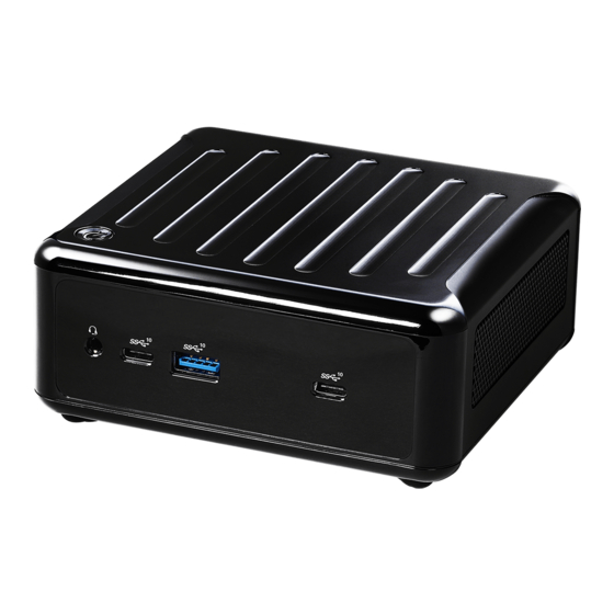
NUC BOX-J6412 Chapter 2 Product Overview This chapter provides diagrams showing the location of important components of the NUC-J6412. 2.1 Front View Description Audio(Mic-in, Line-out) USB 3.2 Gen2 (Type C) USB 3.2 Gen2 (Type A) -
Page 12: Rear View
2.2 Rear View Description DC-IN USB 3.2 Gen2 (Type A) HDMI RJ-45 USB 2.0 DisplayPort RJ-45 * There are two LEDs on the LAN port. Please refer to the table below for the LAN port LED indications. ACT/LINK LED SPEED LED LAN Port Activity / Link LED Speed LED... -
Page 13: Inside View
NUC BOX-J6412 2.3 Inside View Description SO-DIMM Slot SATA 3.0 Connector M.2 Slot (Key M, 2242/2260/2280) M.2 Slot (Key E, 2230 PCIe x1, USB 2.0 for Wireless) Hard disk drive tray (compatible with 2.5" SATA HDD/SSD) SO-DIMM memory, hard drive and M.2 SSD are not included with this system. -
Page 14: Chapter 3 Hardware Installation
Chapter 3 Hardware Installation This chapter helps you install or remove important components. 3.1 How to Remove the Bottom Case 1. Remove the four screws on the bottom case. 2. Then lift up and remove the bottom panel.. -
Page 15: How To Install The Wifi Module
NUC BOX-J6412 3.2 How to Install the WiFi Module 1. Locate the WiFi Module slot on the motherboard. 2. Carefully insert the WiFi Module into the slot. 3. Tighten the screw to secure the WiFi Module to the motherboard. -
Page 16: How To Remove The M.2 Ssd And The Bracket
3.3 How to Remove the M.2 SSD and the Bracket 1. Release the screw and carefully remove the M.2 SSD. 2. Release the screw and remove the bracket from the motherboard. -
Page 17: How To Install The M.2 Ssd
NUC BOX-J6412 3.4 How to Install the M.2 SSD 1. Locate the M.2 slot on the motherboard. 2. Carefully insert the M.2 SSD into the slot. 3. Tighten the screw to secure the M.2 SSD to the motherboard. -
Page 18: How To Install The 2.5-Inch Hard Drive
3.5 How to Install the 2.5-inch Hard Drive 1. Remove the four screws on the bottom case. Then lift up and remove the bottom panel. 2. Attach the HDD to the hard drive mounting bracket and secure it using the four screws. - Page 19 NUC BOX-J6412 3. Connect the SATA Data and Power Cable to the HDD. 4. Connect the SATA Data and Power Cable to the HDD.
- Page 20 5. Connect the SATA Cable to the connector. 6. Then reinstall the bottom panel.
-
Page 21: How To Install The Memory Modules (Ddr4)
NUC BOX-J6412 3.6 How to Install the Memory Modules (DDR4) 1. The NUC BOX-J6412 Series requires DDR4 SO-DIMM. 2. For dual channel configuration, you always need to install identical (the same brand, speed, size and chip-type) DDR4 SO-DIMM pairs. The SO-DIMM only fits in one correct orientation. It will cause permanent damage to the motherboard and the DIMM if you force the DIMM into the slot at incorrect orientation. -
Page 22: Chapter 4 Motherboard (Nuc-J6412)
Chapter 4 Motherboard (NUC-J6412) 4.1 Motherboard Layout Top View: 1 : M.2 Key-M Socket (M2_M1) 2 : M.2 Key-E Socket (M2_E1) 3 : Clear CMOS Header (CLRMOS1) 4 : Front Panel Audio Header (HD_AUDIO1) 5 : USB 2.0 Connector (USB2_6_7) 6 : COM Port Header (RS232/422/485) 7 : SATA3 Port (SATA3_1) 8 : SIO_AT1... - Page 23 NUC BOX-J6412 Bottom View: 10 : Power Button (PWR_BTN1) 11 : Fan Connector (FAN1) 12 : Battery Connector (BAT1) 13 : ESPI Connector (ESPI)
-
Page 24: Motherboard Specifications
4.2 Motherboard Specifications Form Dimensions NUC 4.09" x 4.02" (104 x 102mm) Factor ® Intel ElkHart Lake SoC Processors NUC-J6412 (J6412, QC, Max Speed up to Processor 2.6GHz, 10W) System Chipset BIOS AMI SPI 256 Mbit Technology Dual Channel DDR4 3200 MHz Memory Capacity 32GB (16 GB per DIMM) - Page 25 NUC BOX-J6412 2 x USB 2.0 (1 x 2.00 pitch header) 1 x COM(RS232/422/485) Internal Infineon SLB9670VQ2.0 Connector Audio line in /out (share with audio Jack, by BIOS Header setting) 1 x M.2 (KEY M, 2242/2260/2280) with PCIe x1 and SATA3 for SSD Storage *M.2 Key M 2280(Supported by bracket)
-
Page 26: Jumpers Setup
4.3 Jumpers Setup The illustration shows how jumpers are setup. When the jumper cap is placed on pins, the jumper is “Short”. If no jumper cap is placed on pins, the jumper is “Open”. The illustration shows a 3-pin jumper whose pin1 and pin2 are “Short”... -
Page 27: Onboard Headers And Connectors
NUC BOX-J6412 4.4 Onboard Headers and Connectors Onboard headers and connectors are NOT jumpers. Do NOT place jumper caps over these headers and connectors. Placing jumper caps over the headers and connectors will cause permanent damage of the motherboard! SATA3 Port... - Page 28 System Panel Header This header accommodates several system front panel (9-pin PANEL1) HDLED+ PLED+ functions. HDLED- (see p.8, No. 9) PLED- PWRBTN# RESET# DUMMY Connect the power switch, reset switch and system status indicator on the chassis to this header according to the pin assignments below. Note the positive and negative pins before connecting the cables.
- Page 29 NUC BOX-J6412 Back Side: Power Button (PWR_BTN1) (see p.9, No. 10) Fan Connector +12V (FAN1) (see p.9, No. 11) FAN_SPEED FAN_SPEED_CONTROL Battery Connector (BAT1) (see p.9, No. 12) ESPI Connector (ESPI1) (see p.9, No. 13)
- Page 30 4.5 Expansion Slots (M.2 Slots) There are 2 M.2 slots on this motherboard. M.2 for SSD: 1 x M.2 (KEY M, 2242/2260/2280) with PCIe x1 and SATA3 for SSD. * M.2 Key M 2280(Supported by bracket) M.2 for Wi-Fi: 1 x M.2 (Key E, 2230) with PCIe x1 and USB 2.0 for Wireless. M.2 Key-M Socket (M2_M1) M.2 Key-E Socket (M2_E1)
-
Page 31: Chapter 5 Uefi Setup Utility (Nuc-J6412)
NUC BOX-J6412 Chapter 5 UEFI Setup Utility (NUC-J6412) 5.1 Introduction This section explains how to use the UEFI SETUP UTILITY to configure your system. The UEFI chip on the motherboard stores the UEFI SETUP UTILITY. You may run the UEFI SETUP UTILITY when you start up the computer. Please press <F2>... -
Page 32: Main Screen
5.1.2 Navigation Keys Please check the following table for the function description of each navigation key. Navigation Key(s) Function Description Moves cursor left or right to select Screens Moves cursor up or down to select items + / - To change option for the selected items <Enter>... -
Page 33: Advanced Screen
NUC BOX-J6412 5.3 Advanced Screen In this section, you may set the configurations for the following items: CPU Configu- ration, Chipset Configuration, Storage Configuration, Super IO Configuration, ACPI Configuration, USB Configuration and Trusted Computing. Setting wrong values in this section may cause the system to malfunction. -
Page 34: Cpu Configuration
5.3.1 CPU Configuration Active Processor Cores Select the number of cores to enable in each processor package. CPU C States Support Enable CPU C States Support for power saving. It is recommended to keep C3, C6 and C7 all enabled for better power saving. Intel Virtualization Technology When this option is set to [Enabled], a VMM (Virtual Machine Architecture) can utilize the additional hardware capabilities provided by Vanderpool... - Page 35 NUC BOX-J6412 CPU Thermal Throttling You may select [Enabled] to enable CPU internal thermal control mechanism to keep the CPU from overheating.
-
Page 36: Chipset Configuration
5.3.2 Chipset Configuration VT-d ® ® Use this to enable or disable Intel VT-d technology (Intel Virtualization Technology for Directed I/O). The default value of this feature is [Enabled]. Share Memory Configure the size of memory that is allocated to the integrated graphics processor when the system boots up. -
Page 37: Storage Configuration
NUC BOX-J6412 5.3.3 Storage Configuration SATA Controller(s) Use this item to enable or disable the SATA Controller feature. SATA Mode Selection Use this to select SATA mode. The default value is [AHCI Mode]. AHCI (Advanced Host Controller Interface) supports NCQ and other new features that will improve SATA disk perfor- mance but IDE mode does not have these advantages. -
Page 38: Super Io Configuration
5.3.4 Super IO Configuration COM1 This allows you to enable or disable the COM1 feature. Type Select Use this to select COM1 port type: [RS232], [RS422] or [RS485]. WDT Timeout Reset Use this to set the Watch Dog Timer. -
Page 39: Acpi Configuration
NUC BOX-J6412 5.3.5 ACPI Configuration Suspend to RAM Use this item to select whether to auto-detect or disable the Suspend-to- RAM feature. Select [Auto] will enable this feature if the OS supports it. Onboard LAN Power On Use this item to enable or disable onboard LAN to turn on the system from the power-soft-off mode. -
Page 40: Usb Configuration
5.3.6 USB Configuration USB Power Control Use this item to control USB power. -
Page 41: Trusted Computing
NUC BOX-J6412 5.3.7 Trusted Computing Security Device Support Enable or disable BIOS support for security device. -
Page 42: Hardware Health Event Monitoring Screen
5.4 Hardware Health Event Monitoring Screen In this section, it allows you to monitor the status of the hardware on your system, including the parameters of the CPU temperature, motherboard temperature, CPU fan speed, chassis fan speed, and the critical voltage. FAN1 Setting This allows you to set FAN1’s speed. -
Page 43: Security Screen
NUC BOX-J6412 5.5 Security Screen In this section, you may set, change or clear the supervisor/user password for the system. Supervisor Password Set or change the password for the administrator account. Only the ad- ministrator has authority to change the settings in the UEFI Setup Utility. -
Page 44: Boot Screen
5.6 Boot Screen In this section, it will display the available devices on your system for you to config- ure the boot settings and the boot priority. Boot From Onboard LAN Use this item to enable or disable the Boot From Onboard LAN feature. Setup Prompt Timeout This shows the number of seconds to wait for setup activation key. -
Page 45: Exit Screen
NUC BOX-J6412 5.7 Exit Screen Save Changes and Exit When you select this option, it will pop-out the following message, “Save configuration changes and exit setup?” Select [OK] to save the changes and exit the UEFI SETUP UTILITY. Discard Changes and Exit When you select this option, it will pop-out the following message, “Discard... -
Page 46: Chapter 6 Software Support
Chapter 6 Software Support 6.1 Install Operating System This motherboard supports various Microsoft ® Windows ® operating systems: 10 64-bit. Because motherboard settings and hardware options vary, use the setup procedures in this chapter for general reference only. Refer your OS documentation for more information.
Need help?
Do you have a question about the NUC BOX-J6412 and is the answer not in the manual?
Questions and answers