
Subscribe to Our Youtube Channel
Related Manuals for ASRock Industrial iBOX 250 Series


Summary of Contents for ASRock Industrial iBOX 250 Series
- Page 1 NUC BOX-1260P NUC BOX-1240P NUC BOX-1220P iBOX 250 Series User Manual Version 1.0 Published May 2022 User Manual...
- Page 2 In no event shall ASRock Industrial, its directors, officers, employees, or agents be liable for any indirect, special, incidental, or consequential damages (including damages for loss of...
- Page 3 Replaceable batteries CAUTION RISK OF EXPLOSION IF BATTERY IS REPLACED BY AN INCORRECT TYPE. DISPOSE OF USED BATTERIES ACCORDING TO THE INSTRUCTIONS CAUTION (or Warning) Hot surface Do not touch The equipment intended only for use in a Restricted Access Area. This product should be connected by means of a power cord to a socket-outlet with earthing connection.
- Page 4 Contact Information If you need to contact ASRock Industrial or want to know more about ASRock Industrial, you’re welcome to visit ASRock Industrial’s website at https://www.asrockind.com; or you may contact your dealer for further information. ASRock Industrial Incorporation Email: Info_ipc@asrockind.com...
-
Page 5: Table Of Contents
How to Install the Memory Modules How to Install the Wall Mounting Brackets How to Install the VESA Bracket (Optional) How to Install the Din Rail Mounting Bracket (Optional) 3.10 Positions of the iBOX 250 Series Chapter 4 Motherboard Motherboard Layout Motherboard Specifications Jumpers Setup... - Page 6 Onboard Headers and Connectors Expansion Slots (M.2 Slots) Chapter 5 UEFI Setup Utility Introduction 5.1.1 Entering BIOS Setup 5.1.2 UEFI Menu Bar 5.1.3 Navigation Keys Main Screen Advanced Screen 5.3.1 CPU Configuration 5.3.2 Chipset Configuration 5.3.3 Storage Configuration 5.3.4 Super IO Configuration 5.3.5 ACPI Configuration 5.3.6 USB Configuration 5.3.8 Trusted Computing...
-
Page 8: Chapter 1 Introduction
Because the hardware specifications might be updated, the content of this documentation will be subject to change without notice. 1.1 Package Contents • iBOX 250 Series • 1 x 19V/65W power adapter • 1 x SATA cable • 1 x M.2 screw •... -
Page 9: Product Specifications
1.2 Product Specifications Others Processor System OS Support Intel Elkhart Lake SoC Processors ® iBOX-250J (J6412, QC, Max Speed Up to 2.6GHz, 10W) Certificatio Chipset Packing Lis BIOS AMI SPI 256 Mbit Memory Technology Dual Channel DDR4 3200 MHz Capacity 32GB (16GB per DIMM) Socket 2 x 260-pin SO-DIMM... - Page 10 Ethernet 2 x 2.5 Gigabit LAN 1 x USB 3.2 Gen2, 1 x USB 2.0 iBOX 250 Series Audio Watchdog Timer Output From Super I/O to drag RESETCON# Interval 256 Segments, 0, 1, 2, ...255sec Power Requirements Input PWR 9~36V DC-In...
-
Page 11: Block Diagram
1.3 Block Diagram SBC-250J LVDS/eDP Chrontel SO-DIMM LVDS/eDP Channel A By pass mode CH7513 DDR4 SO-DIMM HDMI Channel B HDMI DDR4 Connector IT66318 PCIe x1 M.2 Key E Realtek USB 2.0 x1 Connector RTD2168 PCIe x1 M.2 Key M USB 3.2 Gen1 x1 USB 3.2/USB 2.0 USB 2.0 x2 Header... -
Page 12: Chapter 2 Product Overview
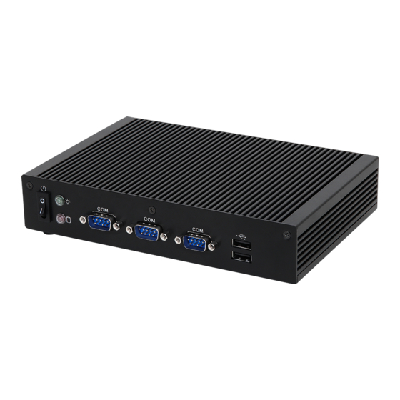
250 Series Chapter 2 Product Overview This chapter provides diagrams showing the location of important components of the iBOX 250 Series. 2.1 Front View Description Power button 3 x COM Port 2 x USB 2.0 (Type A) -
Page 13: Rear View
2.2 Rear View Description 2 x RJ-45 (2.5G LAN)* HDMI USB 3.2 Gen2 (Type A) USB 2.0 (Type A) * There are two LEDs on the LAN port. Please refer to the table below for the LAN port LED indications. ACT/LINK LED SPEED LED LAN Port... -
Page 14: Inside View
250 Series 2.3 Inside View Description SATA 3.0 Connector 1 x M.2 (Key M, 2242/2260/2280) with PCIe x1 for SSD 1 x M.2 (Key E, 2230) with PCIe x1 and USB 2.0 for Wireless 1 x M.2 (Key B, 3042/3052) with PCIe x1/USB 3.2 and USB 2.0 and SIM... -
Page 15: Chapter 3 Hardware Installation
Chapter 3 Hardware Installation This chapter helps you install or remove important components. 3.1 How to Remove the Bottom Case Remove the four screws on the bottom case. Then lift up and remove the bottom panel. -
Page 16: How To Install The Wifi Module
250 Series 3.2 How to Install the WiFi Module 1. Locate the WiFi Module slot on the motherboard. 2. Carefully insert the WiFi Module into the slot at a 30-degree angle. 3. Tighten the screw to secure the WiFi Module to the motherboard. -
Page 17: How To Install The M.2 Ssd
3.3 How to Install the M.2 SSD 1. Locate the M.2 slot on the motherboard. 2. Carefully insert the M.2 SSD (Type 2280) into the slot at a 30-degree angle. Tighten the screw to secure the M.2 SSD (Type 2280) to the motherboard. -
Page 18: How To Install The 45 Lte/5G Module
250 Series 3.4 How to Install the 45 LTE/5G Module 1. Locate the 4G LTE/5G module slot on the motherboard. 2. Carefully insert the 4G LTE/5G Module into the slot at a 30-degree angle. 3. Tighten the screw to secure the 4G LTE/5G Module to the motherboard. -
Page 19: How To Install The 2.5-Inch Hard Drive
3.5 How to Install the 2.5-inch Hard Drive 1. Remove the four screws on the bottom case. Then lift up and remove the bottom panel. 2. Attach the HDD cage to the bottom panel and secure it with screws. Then connect the SATA Data and Power Cable to the HDD. - Page 20 4. Secure four screws and reinstall the bottom panel. For iBOX 250 Series, it is not recommended to install 2.5” HDD. If you install the 2.5” HDD, please keep the iBOX 250 Series in a vertical position to ensure better cooling perfor-...
-
Page 21: How To Install The Memory Modules
3.6 How to Install the Memory Modules (DDR4 Low Voltage (1.2V)) The iBOX 250 Series requires DDR4 SO-DIMM (1.2V). . For dual channel configuration, you always need to install identical (the same brand, speed, size and chip-type) DDR4 SO-DIMM pairs. -
Page 22: How To Install The Wall Mounting Brackets
3.7 How to Install the Wall Mounting Brackets 1. Remove the four rubber feet on the base of the iBOX 250 Series. 2. Attach the wall mounting brackets to the base of the iBOX 250 Series and secure them with screws. -
Page 23: How To Install The Vesa Bracket (Optional)
3.8 How to Install the VESA Bracket (Optional) 1. Attach the two screws to the base of the iBOX 250 Series. Attach the VESA Bracket to the rear of a compatible display using the four screws. *Choose mounting holes depending on the mounting hole pattern of your LCD screen (75 mm ×... -
Page 24: How To Install The Din Rail Mounting Bracket (Optional)
3.9 How to Install the Din Rail Mounting Bracket (Optional) Attach the Din Rail Bracket to the base of the iBOX 250 Series and secure it with screws. Din Rail Bracket is not provided by default. Please purchase it seperately if needed. -
Page 25: Positions Of The Ibox 250 Series
3.10 Positions of the iBOX 250 Series The iBOX 250 Series can be placed in vertical or horizontal position. Horizontal Position Vertical Position VESA-mounted Please note that keeping the iBOX 250 Series in a vertical position will ensure better cooling performance. -
Page 26: Chapter 4 Motherboard
250 Series Chapter 4 Motherboard 4.1 Motherboard Layout CLRMOS1 SIO_AT1_DACC1 DDR4_A1 (Support DDR4 Only) BUZZ1 BLT_VOL1 SPEAKER1 DDR4_B1 (Support DDR4 Only) PNL_PWR1 HD_AUDIO1 SBC-250 BKT_PWR1 Industrial BLT_EN_PWM1 BLT_PWR1 BLT_PWM1 M2_M1 LVDS1 BIOS Chip HDMI1 M2_E1 CPU_FAN1 SATA_PWR1 LAN1 LAN2... - Page 27 1 : Front Panel Audio Header (HD_AUDIO1) 2 : 2W Audio AMP Output Wafer (SPEAKER1) 3 : SIO_AT1_DACC1 4 : Clear CMOS Header (CLRMOS1) 5 : Chassis Intrusion Header (CI1) 6 : 2-Pin Buzzer Header (BUZZ1) 7 : Panel Power Selection (LCD_VCC) (PNL_PWR1) 8 : Backlight Control (BLT_VOL1) 9 : Backlight Power Select (LCD_BLT_VCC) (BKT_PWR1) 10 : Inverter Power Control Wafer (BLT_PWR1)
-
Page 28: Motherboard Specifications
250 Series 4.2 Motherboard Specifications 3.5”SBC (5.8-in x 4-in x 0.87-in, 14.7 cm x 10.2 cm x 2.20 Form Factor Dimensions cm)) ® Intel Elkhart Lake SoC Processors SBC-250J (J6412, QC, Max Speed Up to 2.6GHz, 10W) SBC-250D (J6426, QC, Max Speed Up to 3.0GHz, 10W) Processor SBC-250L (N6210, DC, Max Speed Up to 2.6GHz, 6.5W) - Page 29 1 x USB 3.2 Gen1 (1 x USB 3.1 header ) 1 x USB 2.0 (1 x USB 3.1 header) 4 x USB 2.0 (2 x 2.54 pitch header) COM1, COM2, COM4 (RS-232) COM3 (RS-232/422/485) GPIO 4 x GPI, 4 x GPO Internal Connector LVDS 1 (Connector with LVDS/eDP signal, switch by BIOS)
-
Page 30: Jumpers Setup
250 Series 4.3 Jumpers Setup The illustration shows how jumpers are setup. When the jumper cap is placed on pins, the jumper is “Short.” If no jumper cap is placed on pins, the jumper is “Open. ” The illustration shows a 3-pin jumper whose pin1 and pin2 are “Short”... - Page 31 Chassis Intrusion Header Setting Description Open Normal (Default) (2-pin CI1) Short Active Case Open (see p. 19, No. 5) This motherboard supports CASE OPEN detection feature that detects if the chassis cover has been removed. This feature requires a chassis with chassis intrusion detection design. Panel Power Selection (LCD_VCC) Setting Description...
- Page 32 250 Series GPIO Default Setting Setting Description Pull-High (Default) (3-pin JGPIO_SET1) Pull-Low (see p. 19, No. 22) The header is used for GPIO default value setting for either pull high or pull low. Pulling the header to a high/low value means the voltage is anchored to VCC/GND, in a stable, non- floating state.
-
Page 33: Onboard Headers And Connectors
4.4 Onboard Headers and Connectors Onboard headers and connectors are NOT jumpers. Do NOT place jumper caps over these headers and connectors. Placing jumper caps over the headers and connectors will cause per- manent damage to the motherboard! Front Panel Audio Header Signal Name Signal Name MIC2_L... - Page 34 250 Series Backlight Power Connector Signal Name (6-pin BLT_PWR1) (see p. 19, No. 10) BL CTL BL EN LCD_BLT_VCC LCD_BLT_VCC LVDS Panel Connector (40-pin LVDS1) • eDP by pass mode pin definition: (see p. 19, No. 11) Signal Name...
- Page 35 CPU Fan Connector (+12V) Signal Name (4-pin CPU_FAN1) +12V (see p. 19, No. 13) CPU_FAN_SPEED FAN_SPEED_CONTROL Please connect the CPU fan cable to the fan connector and match the black wire to the ground pin. The board offers three 4-pin CPU fan (Smart Fan) connectors which are compatible with 3-pin CPU fan.
- Page 36 250 Series Internal COM Port Headers (RS232/422/485) Signal Name Signal Name DDCD#1 RRXD1 COM3 (RS232/422/485)* TTXD1 DDTR#1 COM1, 2, 4 (RS232) DDSR#1 (9-pin COM1~4) RRTS#1 CCTS#1 (see p. 19, No. 21) RRI#1 There are four 2.54mm-pitch COM port headers (COM1~COM4), with COM3 port support- ing RS232/422/485, and with COM1, 2, 4 ports supporting RS232.
- Page 37 ESPI Connector Signal Name (20-pin ESPI1) C_ESPI_CLK (see p. 19, No. 24) C_ESPI_CS# DEBUG_RESET The header is reserved for Port 80 code display and for debugging purposes. SMB_CLK_MAIN SMB_DATA_MAIN C_ESPI_IO0 C_ESPI_IO1 C_ESPI_IO2 C_ESPI_IO3 +3VSB C_ESPI_ALERT# Digital Input/Output Pin Header Signal Name Signal Name SIO_GP34 PMC_TGPIO0...
- Page 38 250 Series Connect the power switch, reset switch and system status indicator on the chassis to this header according to the pin assignments below. Note the positive and negative pins before connecting the cables. PWRBTN (Power Switch): Connect to the power switch on the chassis front panel. You may configure the way to turn off your system using the power switch.
-
Page 39: Expansion Slots (M.2 Slots)
4.5 Expansion Slots (M.2 Slots) There are 3 M.2 sockets and 1 SIM socket on this motherboard. SIM Socket (SIM1): SIM socket connected to M.2 key B. M.2 Key-M Socket (M2_M1): M.2 (Key M, 2242/2260/2280) with PCIe x1 for SSD. M.2 Key-B Socket (M2_B1): M.2 (Key B, 3042/3052) with PCIe x1/USB 3.2 and USB 2.0 and SIM for 4G/5G. -
Page 40: Chapter 5 Uefi Setup Utility
Chapter 5 UEFI Setup Utility 5.1 Introduction ASRock Industrial UEFI (Unified Extensible Firmware Interface) is a BIOS utility which offers tweak-friendly options in an advanced viewing interface. The UEFI system works with a USB mouse and offers users a faster, sleeker experience. -
Page 41: Uefi Menu Bar
5.1.2 UEFI Menu Bar The top of the screen has a menu bar with the following selections: Main For setting system time/date information For advanced system configurations Advanced H/W Monitor Displays current hardware status Security For security settings Boot For configuring boot settings and boot priority Exit Exit the current screen or the UEFI Setup Utility Because the UEFI software is constantly being updated, the following UEFI setup... -
Page 42: Navigation Keys
250 Series 5.1.3 Navigation Keys Use < > key or < > key to choose among the selections on the menu bar, and use < > key or < > key to move the cursor up or down to select items, then press <Enter>... -
Page 43: Main Screen
5.2 Main Screen When you enter the UEFI Setup Utility, the Main screen will appear and display the sys- tem overview. Because the UEFI software is constantly being updated, the following UEFI setup screens and descriptions are for reference purpose only, and they may not exactly match what you see on your screen. -
Page 44: Advanced Screen
250 Series 5.3 Advanced Screen I n t h i s s ec t ion, you may s et t he con f ig u r at ions for t he fol low i ng items: CPU Configuration, Chipset Configuration, Storage Configuration, Super IO Configuration,... -
Page 45: Cpu Configuration
5.3.1 CPU Configuration Active Processor Cores This allows you to select the number of cores to enable in each processor package. CPU C States Support This allows you to enable CPU C States Support for power saving. It is recommended to keep C3, C6 and C7 all enabled for better power saving. - Page 46 250 Series Intel Virtualization Technology When this option is set to [Enabled], a VMM (Virtual Machine Architecture) can utilize the additional hardware capabilities provided by Vanderpool Technology. This option will be hidden if the installed CPU does not support Intel Virtualization Technology.
-
Page 47: Chipset Configuration
5.3.2 Chipset Configuration VT-d Intel® Virtualization Technology for Directed I/O helps your virtual machine monitor better utilize hardware by improving application compatibility and reliability, and providing additional levels of manageability, security, isolation, and I/O performance. Configuration options: [Enabled] [Disabled] Share Memory Share memory allows you to configure the size of memory that is allocated to the integrat- ed graphics processor when the system boots up. - Page 48 250 Series Active LVDS Use this to enable or disable the LVDS. The default value is [Disabled]. Set the item to [En- abled]. Then press <F10> to save the setting and restart the system. Now the default value of Active LVDS is changed to ENABLE (F9 load default is also set to Enabled) Change the setting from [Enabled] to [Disabled], and then press <F10>...
-
Page 49: Storage Configuration
5.3.3 Storage Configuration SATA Controller(s) The option allows you to enable or disable the SATA controllers. Configuration options: [Enabled] [Disabled] SATA Mode Selection AHCI supports new features that improve performance. Configuration option: [AHCI] AHCI (Advanced Host Controller Interface) supports NCQ and other new features that will improve SATA disk performance. - Page 50 250 Series Hard Disk S.M.A.R.T. S.M.A.R.T stands for Self-Monitoring, Analysis, and Reporting Technology. It is a monitoring system for computer hard disk drives to detect and report on various indicators of reliability. Configuration options: [Enabled] [Disabled]...
-
Page 51: Super Io Configuration
5.3.4 Super IO Configuration COM1 Configuration Use this to set parameters of COM1. COM2 Configuration Use this to set parameters of COM2. COM3 Configuration Use this to set parameters of COM3. Type Select Use this to select COM3 port type: [RS232], [RS422] or [RS485]. COM4 Configuration Use this to set parameters of COM4. -
Page 52: Acpi Configuration
250 Series 5.3.5 ACPI Configuration Suspend to RAM Use this item to select whether to auto-detect or disable the Suspend-to-RAM feature. Select [Auto] will enable this feature if the OS supports it. Onboard LAN Power On Use this item to enable or disable onboard LAN to turn on the system from the power-soft- off mode. -
Page 53: Usb Configuration
5.3.6 USB Configuration USB Power Control Use this option to control USB power. Configuration options: [Always Enabled] [Default Setting] M.2 Key_B USB Configuration Use this item to enable or disable M.2 Key_B USB Configuration. -
Page 54: Trusted Computing
250 Series 5.3.8 Trusted Computing NOTE: Options vary depending on the version of your connected TPM module. Security Device Support The item allows you to Enable or disable BIOS support for security device. Active PCR banks This item displays active PCR Banks. - Page 55 Platform Hierarchy This item allows you to enable or disable Platform Hierarchy. Configuration options: [Enabled] [Disabled] Storage Hierarchy This item allows you to enable or disable Storage Hierarchy. Configuration options: [Enabled] [Disabled] Endorsement Hierarchy This item allows you to enable or disable Endorsement Hierarchy.
-
Page 56: Hardware Health Event Monitoring Screen
250 Series 5.4 Hardware Health Event Monitoring Screen This section allows you to monitor the status of the hardware on your system, including the parameters of the CPU temperature, motherboard temperature, CPU fan speed, and the critical voltage. NOTE: Options vary depending on the features of your motherboard. -
Page 57: Security Screen
5.5 Security Screen In this section you may set or change the supervisor/user password for the system. You may also clear the user password. Supervisor Password Set or change the password for the administrator account. Only the administrator has the authority to change the settings in the UEFI Setup Utility. -
Page 58: Boot Screen
250 Series 5.6 Boot Screen This section displays the available devices on your system for you to configure the boot settings and the boot priority. Boot From Onboard LAN Use this item to enable or disable the Boot From Onboard LAN feature. -
Page 59: Exit Screen
5.7 Exit Screen Save Changes and Exit When you select this option, the following message “Save configuration changes and exit setup?” will pop out. Select [Yes] to save the changes and exit the UEFI SETUP UTILITY. Discard Changes and Exit When you select this option, the following message “Discard changes and exit setup?”... -
Page 60: Chapter 6 Software Support
250 Series Chapter 6 Software Support 6.1 Install Operating System ® ® This motherboard supports various Microsoft Windows operating systems: 10 64-bit / 11 64-bit. Because motherboard settings and hardware options vary, use the setup procedures in this chapter for general reference only. Refer your OS documentation for more information.
Need help?
Do you have a question about the iBOX 250 Series and is the answer not in the manual?
Questions and answers