
Subscribe to Our Youtube Channel
Related Manuals for ASRock Industrial SBC-250


Summary of Contents for ASRock Industrial SBC-250
- Page 1 SBC-250 User Manual Version 1.0 Published June 15, 2022 Copyright©2022 ASRockInd INC. All rights reserved.
- Page 2 Version 1.0 Published June 15, 2022 Copyright©2022 ASRock INC. All rights reserved. Copyright Notice: No part of this documentation may be reproduced, transcribed, transmitted, or translated in any language, in any form or by any means, except duplication of documentation by the purchaser for backup purpose, without written consent of ASRockInd Inc.
- Page 3 The terms HDMI® and HDMI High-Definition Multimedia Interface, and the HDMI logo are trademarks or registered trademarks of HDMI Licensing LLC in the United States and other countries. CAUTION: RISK OF EXPLOSION IF BATTERY IS REPLACED BY AN INCORRECT TYPE. DISPOSE OF USED BATTERIES ACCORDING TO THE INSTRUCTIONS.
-
Page 4: Table Of Contents
Contents 1 Introduction ............5 1.1 Package Contents ............5 1.2 Specifications ..............6 1.3 Motherboard Layout ............8 1.4 I/O Panel ................ 10 2 Installation ............11 2.1 Screw Holes ..............11 2.2 Pre-installation Precautions ........... 11 2.3 Installation of Memory Modules (SO-DIMM) ....12 2.4 Expansion Slots ............. -
Page 5: Introduction
Chapter 1: Introduction Thank you for purchasing ASRockInd SBC-250 motherboard, a reliable mother- board produced under ASRockInd’s consistently stringent quality control. It delivers excellent performance with robust design conforming to ASRockInd’s commitment to quality and endurance. In this manual, chapter 1 and 2 contain introduction of the motherboard and step-by- step guide to the hardware installation. -
Page 6: Specifications
1.2 Specifications Form Dimensions 3.5”SBC (5.8-in x 4-in) Factor ® Intel Elkhart Lake SoC Processors SBC-250J (J6412, QC, Max Speed Up to 2.6GHz, 10W) SBC-250D (J6426, QC, Max Speed Up to 3.0GHz, 10W) Processor SBC-250L (N6210, DC, Max Speed Up to System 2.6GHz, 6.5W) SBC-250N (N6415, QC, Max Speed Up to... - Page 7 HDMI 1 x HDMI 2.0b Rear I/O Ethernet 2 x 2.5 Gigabit LAN 1 x USB 3.2 Gen2, 1 x USB 2.0 1 x USB 3.2 Gen1 (1 x USB 3.1 header ) 1 x USB 2.0 (1 x USB 3.1 header) 4 x USB 2.0 (2 x 2.54 pitch header) COM1, COM2, COM4 (RS-232) COM3 (RS-232/422/485)
-
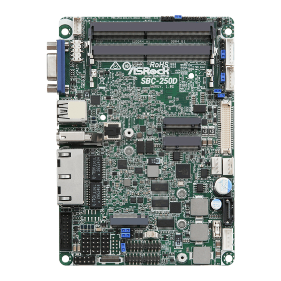
Page 8: Motherboard Layout
1.3 Motherboard Layout... - Page 9 1 : Front Panel Audio Header 2 : 2W Audio AMP Output Wafer Backlight 3 : SIO_AT_DACC1 4 : Clear CMOS Header (CLRMOS1) 5 : Chassis Intrusion Header (CI1) 6 : 2-Pin Buzzer Header 7 : Panel Power Selection (LCD_VCC) (PNL_PWR1) 8 : Backlight Control (BLT_VOL1) 9 : Backlight Power Select (LCD_BLT_VCC) (BKT_PWR1) 10 : Inverter Power Control Wafer (BLT_PWR1)
-
Page 10: I/O Panel
1.4 I/O Panel VGA Port (VGA1) HDMI Port (HDMI1) USB3.2 Gen2 Port (USB3_4) LAN Port (LAN1)* USB2.0 Port (USB3_3) LAN Port (LAN2)* * There are two LED next to the LAN port. Please refer to the table below for the LAN port LED indications. -
Page 11: Installation
Chapter 2: Installation This is a 3.5” SBC (5.8-in x 4-in) form factor motherboard. Before you install the motherboard, study the configuration of your chassis to ensure that the motherboard fits into it. Make sure to unplug the power cord before installing or removing the motherboard. -
Page 12: Installation Of Memory Modules (So-Dimm)
2.3 Installation of Memory Modules (SO-DIMM) SBC-250 provides two 260-pin DDR4 (Double Data Rate 4) SO-DIMM slots. Step 1. Align a SO-DIMM on the slot such that the notch on the SO-DIMM matches the break on the slot. 1. The SO-DIMM only fits in one correct orientation. It will cause permanent damage to the motherboard and the SO-DIMM if you force the SO-DIMM into the slot at incorrect orientation. -
Page 13: Expansion Slots
2.4 Expansion Slots (M.2 and SIM Sockets) There are 3 M.2 and 1 SIM sockets on this motherboard. SIM Socket (SIM1): SIM socket connected to M.2 key B. M.2 Key-M Socket (M2_M1): M.2 (Key M, 3042/3060/2280) with PCIe x1 for SSD. M.2 Key-B Socket (M2_B1): M.2 (Key B, 3042/3052) with PCIex1/USB 3.2 and USB 2.0 and SIM for 4G/5G. -
Page 14: Jumpers Setup
2.5 Jumpers Setup The illustration shows how jumpers are setup. When the jumper cap is placed on pins, the jumper is “Short”. If no jumper cap is placed on pins, the jumper is “Open”. The illustration shows a 3-pin jumper whose pin1 and pin2 are “Short”... - Page 15 SIO_AT_DACC1 1-2 Short: AT Mode 1-2 Open: ATX Mode (4-pin SIO_AT_DACC1) 3-4 Short: ACC (see p.8 No. 3) 3-4 Open: No ACC Note: Auto clear CMOS when system boot improperly. Chassis Intrusion Header This motherboard supports CASE OPEN detection feature (2-pin CI1: see p.8, No.
-
Page 16: Onboard Headers And Connectors
2.6 Onboard Headers and Connectors Onboard headers and connectors are NOT jumpers. Do NOT place jumper caps over these headers and connectors. Placing jumper caps over the headers and connectors will cause permanent damage of the motherboard! SATA3 Connector This Serial ATA3 (SATA3) SATA3_1 connector supports SATA data (SATA3_1: see p.8, No. - Page 17 PLED (System Power LED): Connect to the power status indicator on the chassis front panel. The LED is on when the system is operating. The LED keeps blinking when the sys- tem is in S1 sleep state. The LED is off when the system is in S3/S4 sleep state or powered off (S5).
- Page 18 2W Audio AMP Output Wafer Backlight Signal Name SPK L- (4-pin SPEAKER1) SPK L+ (see p.8 No. 2) SPK R+ SPK R- Front Panel Audio Header MIC2_L (9-pin HD_AUDIO1) MIC2_R PRESENCE# (see p.8 No. 1) OUT2_R MIC_RET J_SENS E OUT2_L OUT_RET 1.
- Page 19 LVDS Connector Signal Name Signal Name LCD_BLT_VCC LCD_BLT_VCC (40-pin LVDS1) CON_LBKLT_CTL LCD_BLT_VCC CON_LBKLT_EN (see p.8 No. 11) LVDS_B_CLK# LVDS_B_CLK LVDS_B_DATA3 DPLVDD_EN LVDS_B_DATA3# LVDS_B_DATA2# LVDS_B_DATA2 LVDS_B_DATA1 LVDS_B_DATA1# LVDS_B_DATA0# LVDS_B_DATA0 LVDS_A_CLK LVDS_A_CLK# LVDS_A_DATA3# LVDS_A_DATA3 LVDS_A_DATA2 * eDP by pass mode pin definition: LVDS_A_DATA2# LVDS_A_DATA1# LVDS_A_DATA1...
- Page 20 ESPI Connector (20-pin ESPI1) (see p.8 No. 24) CAN1_2 Connector (Only supported With SBC-250N/SBC-250D) PIN Signal Name PIN Signal Name GPIO (9-pin CAN1_2) (see p.8 No. 23) CAN1_RX0 CAN2_RX0 CAN1_TX0 CAN2_TX0 +3VSB +3VSB...
-
Page 21: Installation Of Rom Socket
2.7 Installation of ROM Socket * Do not apply force to the actuator cover after ic inserted. * Do not apply force to actuator cover when it is opening over 120 degree, Otherwise, the actuator cover may be broken. * The yellow dot (Pin1) on the ROM must be installed at pin1 position of the socket (white arrow area). -
Page 22: Uefi Setup Utility
Chapter 3: UEFI SETUP UTILITY 3.1 Introduction This section explains how to use the UEFI SETUP UTILITY to configure your system. The UEFI chip on the motherboard stores the UEFI SETUP UTILITY. You may run the UEFI SETUP UTILITY when you start up the computer. Please press <F2>... -
Page 23: Navigation Keys
3.1.2 Navigation Keys Please check the following table for the function description of each navigation key. Navigation Key(s) Function Description Moves cursor left or right to select Screens Moves cursor up or down to select items + / - To change option for the selected items <Enter>... -
Page 24: Advanced Screen
3.3 Advanced Screen In this section, you may set the configurations for the following items: CPU Configu- ration, Chipset Configuration, Storage Configuration, Super IO Configuration, ACPI Configuration, USB Configuration and Trusted Computing. Setting wrong values in this section may cause the system to malfunction. -
Page 25: Cpu Configuration
3.3.1 CPU Configuration Active Processor Cores Select the number of cores to enable in each processor package. CPU C States Support Enable CPU C States Support for power saving. It is recommended to keep C3, C6 and C7 all enabled for better power saving. Enhanced Halt State (C1E) Enable Enhanced Halt State (C1E) for lower power consumption. - Page 26 Intel Turbo Boost Technology Use this item to enable or disable Intel Turbo Boost Mode Technology. Turbo Boost Mode allows processor cores to run faster than marked fre- quency in specific conditions. The default value is [Enabled]. CPU Thermal Throttling You may select [Enabled] to enable CPU internal thermal control mechanism to keep the CPU from overheating.
-
Page 27: Chipset Configuration
3.3.2 Chipset Configuration VT-d ® ® Use this to enable or disable Intel VT-d technology (Intel Virtualization Technology for Directed I/O). The default value of this feature is [Disabled]. Share Memory Configure the size of memory that is allocated to the integrated graphics processor when the system boots up. - Page 28 Onboard LAN1 This allows you to enable or disable the Onboard LAN1 feature. Onboard LAN2 This allows you to enable or disable the Onboard LAN2 feature. Onboard HD Audio Select [Auto], [Enabled] or [Disabled] for the onboard HD Audio feature. If you select [Auto], the onboard HD Audio will be disabled when PCI Sound Card is plugged.
-
Page 29: Storage Configuration
3.3.3 Storage Configuration SATA Controller(s) Use this item to enable or disable the SATA Controller feature. SATA Mode Selection Use this to select SATA mode. The default value is [AHCI Mode]. AHCI (Advanced Host Controller Interface) supports NCQ and other new features that will improve SATA disk perfor- mance but IDE mode does not have these advantages. -
Page 30: Super Io Configuration
3.3.4 Super IO Configuration COM1 Configuration Use this to set parameters of COM1. COM2 Configuration Use this to set parameters of COM2. COM3 Configuration Use this to set parameters of COM3. Type Select Use this to select COM3 port type: [RS232], [RS422] or [RS485]. COM4 Configuration Use this to set parameters of COM4. -
Page 31: Acpi Configuration
3.3.5 ACPI Configuration Suspend to RAM Use this item to select whether to auto-detect or disable the Suspend-to- RAM feature. Select [Auto] will enable this feature if the OS supports it. Onboard LAN Power On Use this item to enable or disable onboard LAN to turn on the system from the power-soft-off mode. -
Page 32: Usb Configuration
3.3.6 USB Configuration USB Power Control Use this option to control USB power. M.2 Key_B USB Configuration Enable or disable M.2 Key_B USB Configuration. -
Page 33: Trusted Computing
3.3.7 Trusted Computing Security Device Support Enable or disable BIOS support for security device. -
Page 34: Hardware Health Event Monitoring Screen
3.4 Hardware Health Event Monitoring Screen In this section, it allows you to monitor the status of the hardware on your system, including the parameters of the CPU temperature, motherboard temperature, CPU fan speed, chassis fan speed, and the critical voltage. CPU_FAN1 Setting This allows you to set CPU fan 1’s speed. -
Page 35: Security Screen
3.5 Security Screen In this section, you may set, change or clear the supervisor/user password for the system. Supervisor Password Set or change the password for the administrator account. Only the ad- ministrator has authority to change the settings in the UEFI Setup Utility. Leave it blank and press enter to remove the password. -
Page 36: Boot Screen
3.6 Boot Screen In this section, it will display the available devices on your system for you to config- ure the boot settings and the boot priority. Boot From Onboard LAN Use this item to enable or disable the Boot From Onboard LAN feature. Setup Prompt Timeout This shows the number of seconds to wait for setup activation key. -
Page 37: Exit Screen
3.7 Exit Screen Save Changes and Exit When you select this option, it will pop-out the following message, “Save configuration changes and exit setup?” Select [OK] to save the changes and exit the UEFI SETUP UTILITY. Discard Changes and Exit When you select this option, it will pop-out the following message, “Discard changes and exit setup?”...
Need help?
Do you have a question about the SBC-250 and is the answer not in the manual?
Questions and answers